well, all can say that is i hope that i have your same problem.
Having to cleanup the sawdust means your making stuff!
It did not work. The belts might be too loose still, but they feel a lot tighter than with the Primo, though one has to remember that the belts were at least 30-40cm shorter. I really don’t have a feel for the belts yet.
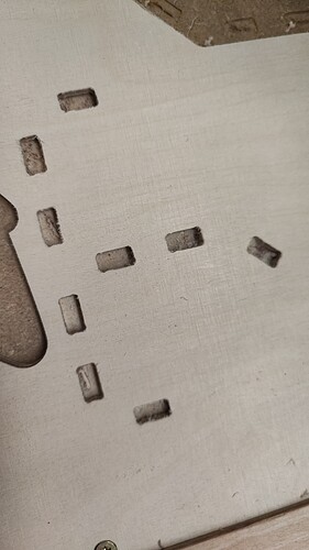
You can see that the holes in the picture are all do not okay and are a bit too big, you can’t make out the dogbones… I played around with the belts after every hole. So the same problems I used to have with the Primo. Funnily enough it’s the only thing where you can see it, those 90° turns. You saw the inlays, they were really tight. They don’t have 90° turns though. ![]()
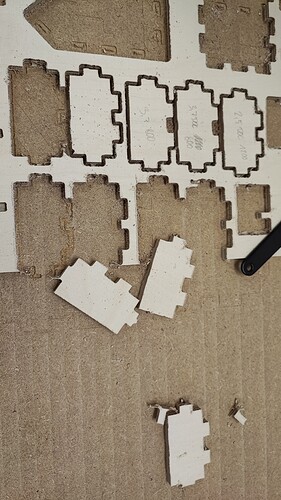
Also funny: The mistakes are 100% repeatable. I cut the same part four times with the same G-Code. They are all exactly the same. I stacked them… The outsides of the joints being too small, the insides too large.
(Side remark: I refuse to go slower than 1200mm/min. It did always work, it has to work… :D)
Not enough likes and comments.
After a year… ![]()
I am answering myself here… ![]() I found this post: Measuring belt tension, squaring and calibration - Shapeoko - Carbide 3D Community Site
I found this post: Measuring belt tension, squaring and calibration - Shapeoko - Carbide 3D Community Site
If he is right, my belt was waaaaaaaaay too loose. I tightened it according to his table, now having 87 Hz per belt. Will cut something later and see whether this was really the problem. If it was indeed the problem, I will tell you and make sure to spread that link. ![]()
/edit: Further reading tells me that this tension might be waaaaaay too much. I am going to try it anyway just to see whether my problem disappears. The load on the belt and stepper shaft is now much higher than it should be. -_- Damn. And I thought this might have been it.
I like the idea to somehow measure the belt tension of the LR3. So far I‘ve just tensioned the belts to what I thought was good enough, but maybe it wasn‘t. Would be great to get to a guidance using the method you referred to. Good luck with it!
We had a guy in the forum do it as well (Belt tension test rig), though he did it with 6mm belts. 10mm belts have a higher allowance than those. Might be something in between. Will keep you posted.
Okay, the belts are not the problem, the speed is not the problem, the DOC is not the problem… Nothing is. I produced 9 identical parts, independent of the setting.
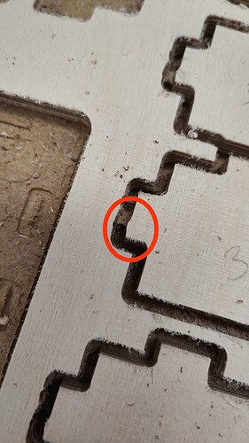
The machine also jerks after having cut the first “layer”, resulting in those little “nubs”:
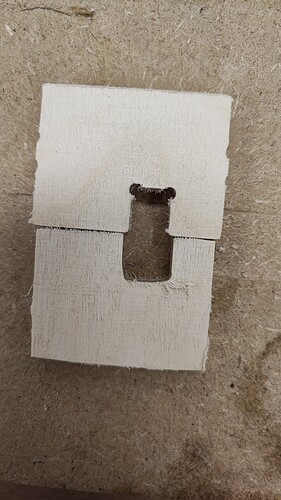
Funnily enough, when I changed from conventional to climb milling, the parts got a mm smaller, also you can clearly see it can cut the dog bones, so it’s got nothing to do with inertia:
So there must be half a mm movement somewhere and I don’t know where. I checked all the screws, tried to wobble the core, but there isn’t any obvious play in it.
Anyone got an idea? Please…
Is the whole gantry twisted? Tap on each corner to see if it is seated or if it taps.
Next suggestion would be wiggle the core.
After that would be check the tram.
WAIT!!!
Grub screw. ![]()
Please check that you have your core properly tensioned on the rails. This seems like something there is allowing the core to shift.
If it isn’t that, then it may be the tool mounts into the core.
The LR3 core is adjusted to the rails via two outer bolts through the bottom holding skate bearings. A couple of people have noted that they did not tighten these enough.
If these are loose you may be able to move the core a little at the bottom, it won’t be firmly held in place to the rails. A tiny bit of tightening to ensure that all 4 bearings on the bottom are held tight to the rails.
Thanks for the ideas, but I checked both of those, the core can only move with the whole gantry. If I push and pull, the whole gantry moves, not the core itself. All the bearings make contact, there is no clicking sound… The tool mount is also rock solid but I’ll double check again.
Thanks for the ideas, I did all of those, it’s all okay. It confuses me a lot. You might recall that I spent several hours on a twisted gantry… ![]()
Maybe I should take the core off and do all the screws again…
Not sure if the clicking sound is a good indication. On mine it makes the sound when moving, though it is firmly in place.
@vicious1 You are not going to love it: When I tighten the bolts at the bottom more, to the place where I can hear the scraping on the braces, the error nearly vanishes (all the other bolts are snug, checked them twice). I would have to tighten them a bit more for the error to completely vanish (my wife interrupted my testing), but then it would like, really scrape. I also noticed that if I tighten the one a bit more, the other one does not make contact any more in some places, so they really have to be tightened equally.
I still think that this might be connected to the 25mm OD version, the plastic on the braces is not as thick as on the other versions, so maybe it bends more easily, pushing the rail out? I am still trying to figure out a good solution, but I guess I will have to tighten it more, see if that works and then file down the braces a bit.
The screws for the struts are barely touching (did that a few weeks ago, we discussed it in detail here), so that’s not the issue, those pushing the rail out (which would actually be good so the core would be a bit tighter…). ![]()
Before I start changing parts maybe we should do a printer calibration check. Print something on your printer that is large and rectangular. As big as possible, from there we need to see if it is the size it is supposed to be and second if the diagonals are the same.
These are triangular parts and if your printer is skewed at all you will be printing significantly smaller or larger braces.
So like the first 5-10mm of a full bed square/cube.
Will do. ![]()
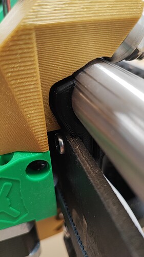
Top is fine:
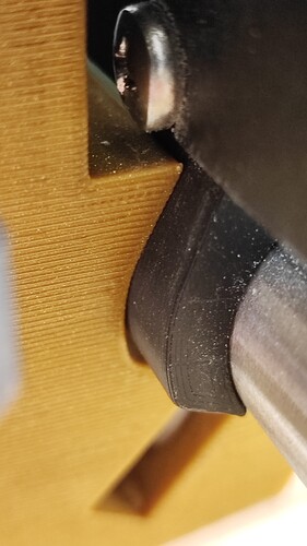
Bottom right now scrapes:
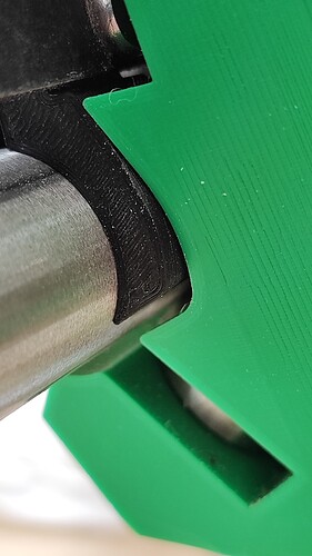
Bottome left is fineish, but close to scraping:
I think it should more look like the top rail, shouldn’t it? -_- Even if I have it really loose and can wobble the core, the gap at the bottom does fit a sheet of paper, it’s hair thin, but not more. Is that right?
