Deflection measurement

Here is my setup using a kitchen scale:

The starting point idea is that I can command the machine to move in small increments to push the rod and register the force as a function of commanded movement.

BUT the scale itself deflects, meaning the deflection of the tool may be less than the commanded movement. If you imagine the extreme case where the tool is infinitely stiff and the scale is soft, then the scale deflects and the force vs. distance relationship is just the spring constant of the scale.

Therefore I have a dial indicator to measure the axial motion of the rod. Then I can distinguish deflection of the tool from deflection of the scale. Tool deflection is commanded motion minus dial indicator motion, and scale deflection is dial indicator motion.

The net result is this:

I have no explanation for the “soft spot” around 1 lb force. I’m guessing it’s probably not real and I need to run the test a few times to see if it appears every time.

I don’t know what the average machine stiffness would be numerically, but I have a feeling my measurements are not representative (i.e. significantly worse than average), for several reasons:

  1. It’s a bit old and creep may have loosened some of the joints relative to when it was new.
  2. The machine is larger than recommended (3 foot working dimension)
  3. It’s still using 6mm belts (and they are long)
  4. This is near maximum Z depth of about 9 inches (!!) below the bottom of the core (double-decker helps, but still…)

In the end this technique sorta works, but it is not really suitable for breaking down the deflection into components. I could measure deflection at low Z and high Z to estimate tilt vs lateral deflection, but I can’t easily apply force and measure deflection of trucks vs. tubes vs. tool mount.

We’ll see. Maybe I can get a better technique.

5 Likes

For measurement like this, there are scales thst use load cells, which have minimal deflection within their measurement range. Or of course you could use a real load cell and an arduino…

Still cheap to use the equipment that you have to get prelimimary data that is “close enough”

3 Likes

Ok, you talked me into it. I have load cells on the way.

What would be cool would be a motor driven mechanism that uses feedback from the load cells to apply a prescribed force to the tool. Maybe a button and it can cycle among a sequence of applied forces, with varying strength in positive and negative X and Y. Not sure yet how far down this path I want to go, or if I just want to keep it simple and make a scale.

I am still thinking about the deflection of the scale relative to the deflection of the tool and whether I can assume that the scale is infinitely stiff relative to the stiffness of the tool. If this assumption is incorrect it will make the tool seem worse than it is.

The remedy could be measuring the deflection of the scale, or it’s probably simpler to leave the tool fixed and pushing the scale into it with a bolt or something.

3 Likes

That is always how I have inagined it. The work table is the reference surface. The scale applies force feom the table (and can flex all it wants) and the tool deflection is measured from the table.

That could be something slipping. Something where the static friction was the initial rigidity, then it slipped in place, until it hit a more rigid edge. Maybe the router wiggling in its mount, for example. It is almost like backlash, but it needed 1lb of initial force to overcome the static friction.

Or it is me fitting a pattern to nothing :slight_smile:

3 Likes

Would it be easier if you measured deflection from the opposite side to the load rather than inline? EDIT- ahh you suggested that!

1 Like

I :heart: flexures.

Bottom left will be anchored to table. Top right attached to spindle.

Pushing/pulling horizontally on the top left, or pushing/pulling vertically on the bottom right should load the tool with a force I can measure. I still have to design those mechanisms, but pushing with my finger it feels like this will work.

6 Likes

Watching with fascination.
I may wish to emulate, although I was going to go with something like your scales version, or actually no scales just measuring…

1 Like

Here it is:

Arduino Mega (overkill but I had handy).
Two load cells (5kg max) and HX711 readers.
OLED (SSD1306 32x128 pixels)
Battery holder 4x AA

Screws (M3) allow pushing in small increments, and rubber bands pull back on the mechanism so that I can measure positive and negative (pulling) forces with a single setup.

Measurements are in pounds, with decimals down to 0.001 pounds (milli-pounds :joy:).

I haven’t set up displacement measurement yet but I did discover my tool mount was cracked. I felt like the stiffness was worse than it should have been (based on feel) and here I was blaming it on other things…

Pulling on it to make it obvious:

Definitely need to fix that before measuring again.

5 Likes

For someone who thinks “accurate” is cutting with a handsaw along a fat sharpie line this is mind boggling!

3 Likes

I can’t decide if this is nasa scientist quality overkill, tim the toolman overkill, or somewhere in between.

It mostly reminds me of Doc from Back to the Future.

3 Likes

But I still want one!

2 Likes

Ok this is just BAD A$$. I cant wait to see what info you get from it. I would love to set up something like this. Not because it matters at the end of the day but just because I love crazy electronics stuff like this. Too bad i suck at actually making them work LOL

1 Like

Are the load cells hard to read from arduino? I have sort of wanted to build a smart scale that could guide me in the kitchen through common recipes, like my pancake recipe. Or something that can plot weight over time for some dumb experiments.

1 Like

I tried to build a propane scale for my Blackstone following this YT video. I never could get it working right and never did figure out what I was messing up. I have several sets of these scales and some break out boards that I swear i got from adafruit that makes wiring them a lot easier but never revisited the project. I need to though. Would love to have home assistant tell me when I need to refill the propane lol. Hopefully before half way though a cook and it stops

3 Likes

It is really pretty easy.

I just watched Jonathan’s video, and that looks much more complicated than what I did. It looks like the IOT system is wanting to mediate the reading of the device, and I would be totally lost. Going direct with native Arduino there are tons of tutorials that make it super easy.

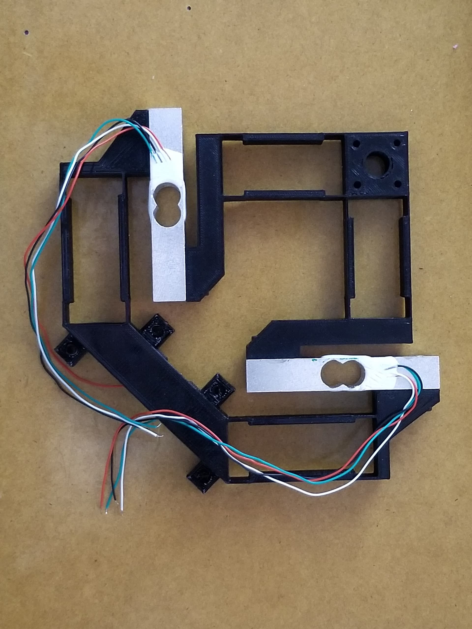
Not an expert, but I think it’s also going to be simpler to hook up the bar-with-hole style load cell, rather than the “bathroom scale” type that has four separate pads that you have to wire together correctly. The bar-with-hole has four wires that are connected directly to the HX711 and the tutorials are pretty clear about which goes where. Then the Arduino reads out the digital value using a library and that’s it. You have to calibrate the weight because the HX711 doesn’t know how sensitive the load cell is, it just produces a readout that’s proportional to weight.

I did it with an Arduino sketch instead of VS Code because for me it’s still simpler that way.

The essential part I’m using is

#include <HX711.h>

#define LOADCELL_DOUT_PIN  3
#define LOADCELL_SCK_PIN  2

HX711 scale1;

float calibration_factor = -225600;   // <--- empirically derive this number

void setup() {
  Serial.begin(9600);
  scale1.begin(LOADCELL_DOUT_PIN, LOADCELL_SCK_PIN);
  scale1.set_scale();
  scale1.tare();
  scale1.set_scale(calibration_factor);
}

void loop() {
  float weight1 = scale1.get_units();
  Serial.println(weight1, 3);
}

In my application it does an automatic tare at power-up, but in the sample code that I stole, there are comments that imply that the tare weight can be hard-coded so that the scale can wake up and know the weight without having to tare the scale.

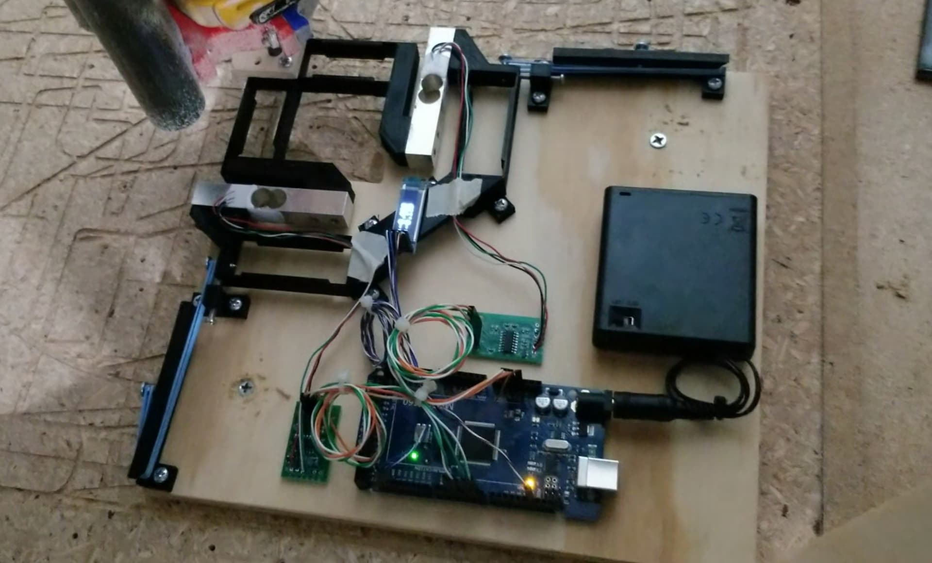
Here is the entire code that I’m running (not cleaned up or anything). Basically just bodged together a load cell tutorial/sample and an OLED sample. The OLED was confusing me until I realized I had to hook up Vcc to 3.3V instead of 5V.

Code
#include <HX711.h>
#include <SPI.h>
#include <Wire.h>
#include <Adafruit_GFX.h>
#include <Adafruit_SSD1306.h>

#define LOADCELL_DOUT_PIN  3
#define LOADCELL_SCK_PIN  2

#define LOADCELL2_DOUT_PIN  6
#define LOADCELL2_SCK_PIN  5

HX711 scale1;
HX711 scale2;

float calibration_factor = -225600;
float calibration_factor2 = 203040;

#define SCREEN_WIDTH 128 // OLED display width, in pixels
#define SCREEN_HEIGHT 32 // OLED display height, in pixels


// Declaration for an SSD1306 display connected to I2C (SDA, SCL pins)
#define OLED_RESET     -1 // Reset pin # (or -1 if sharing Arduino reset pin)
#define SCREEN_ADDRESS 0x3C ///< See datasheet for Address; 0x3D for 128x64, 0x3C for 128x32
Adafruit_SSD1306 display(SCREEN_WIDTH, SCREEN_HEIGHT, &Wire, OLED_RESET);

void setup() {

  Serial.begin(9600);

  if(!display.begin(SSD1306_SWITCHCAPVCC, SCREEN_ADDRESS)) { 
    Serial.println(F("SSD1306 allocation failed"));
    for(;;); // Don't proceed, loop forever
  }

  // Clear the buffer
  display.setTextSize(2);             // Normal 1:1 pixel scale
  display.setTextColor(SSD1306_WHITE);        // Draw white text
  display.clearDisplay();
  display.display();
  display.setCursor(0,0);             // Start at top-left corner
  display.print("Starting..");
  display.display();
    
  // put your setup code here, to run once:
  Serial.begin(9600);
  Serial.println("HX711 calibration sketch");
  Serial.println("Remove all weight from scale");
  Serial.println("After readings begin, place known weight on scale");
  Serial.println("Press + or a to increase calibration factor");
  Serial.println("Press - or z to decrease calibration factor");
  
  scale1.begin(LOADCELL_DOUT_PIN, LOADCELL_SCK_PIN);
  scale1.set_scale();
  scale1.tare(); //Reset the scale to 0
  
  scale2.begin(LOADCELL2_DOUT_PIN, LOADCELL2_SCK_PIN);
  scale2.set_scale();
  scale2.tare(); //Reset the scale to 0
  
  //long zero_factor = scale.read_average(); //Get a baseline reading
  //Serial.print("Zero factor: "); //This can be used to remove the need to tare the scale. Useful in permanent scale projects.
  //Serial.println(zero_factor);
  // Clear the buffer
  display.clearDisplay();
  display.display();

  scale1.set_scale(calibration_factor); //Adjust to this calibration factor
  scale2.set_scale(calibration_factor2); //Adjust to this calibration factor
}

void loop() {
  // truncate floating point so we don't get "-0.000"
  int thou;
  float weight1 = scale1.get_units();
  thou = weight1 * 1000.0f + 0.5;
  weight1 = (float)thou/1000;
  float weight2 = scale2.get_units();
  thou = weight2 * 1000.0f + 0.5;
  weight2 = (float)thou/1000;

  if (1) {
    // put your main code here, to run repeatedly:
    Serial.print("Reading: ");
    Serial.print(weight1, 3);
    Serial.print(", ");
    Serial.print(weight2, 3);
    Serial.print(" lbs"); //Change this to kg and re-adjust the calibration factor if you follow SI units like a sane person
    //Serial.print(" calibration_factor: ");
    //Serial.print(calibration_factor);
    Serial.println();
  }
  
  display.clearDisplay();
  display.setCursor(0,0);             // Start at top-left corner
  if (weight1 >= 0) {
    display.print("X: ");
  }
  else {
    display.print("X:");
  }
  display.println(weight1, 3);
  //display.println("lbs");
  if (weight2 >= 0) {
    display.print("Y: ");
  }
  else {
    display.print("Y:");
  }
  display.print(weight2, 3);
  display.display();

  if (0) {
    if(Serial.available())
    {
      char temp = Serial.read();
      if(temp == '+' || temp == 'a')
        calibration_factor += 10;
      else if(temp == '-' || temp == 'z')
        calibration_factor -= 10;
    }
  }
}

IMO this is squarely within the strength of Arduino, where a novice can get a device working by just plugging in the device and installing a library for it, and it works.

I got four for $20 and it’s already got me thinking where else I might use these.

5 Likes

Thank you for the info! Could the mega be replaced with a ESP8266 or ESP32? i have tons of both of those laying around lol.

1 Like

I was thinking of disassembling an old kitchen scale to get the mechanical parts for free. I guess I would either have to replace the load cell, or get the hx711 connected to the existing one. I’ve put it into my never ending list of projects.

A smart bathroom scale (that had my own software) is appealing too. I would worry it wouldn’t be accurate enough for my weight though.

It definitely can. The magic is all in the hx711 library. Sometimes the esp versions have slight differences. But the video shows tasmota and I have seen esphome support hx711. So the library must exist for esps.

2 Likes

Yeah he uses an esp8266 in the video. Seeing this really making me want to break that stuff out again and try another crack at making the scale lol

So let me ask another question that has probably already been answered and my head is just going in way too many directions. With this scale will we be able to measure the force the primo/LR3 can apply and then use that info to judge better for feeds/speeds and such? I got so lost in oooo new shiny electronic stuff and never really thought about true application lol

1 Like

Jamie is going to post some results, after he fixes the cracked part, I think.

That should give all of us a least an order of magnitude of how much force can be applied before you get X mm deflection. We might also argue about where the deflection is coming from and even make the weakest part more rigid.

If you had this device, you could get a better picture of your own machine’s limits. With that information, you might consider tuning your roughing pass to be less than some amount of load, and a finishing pass size greater than the amount of deflection predicted at that load.

Making up numbers, if you found 1lb of force deflected 0.1mm, you might put 1lb load into a cut calculator and tune your doc or speeds to make that approximately right for your roughing pass, and leave 0.2mm for the finishing pass to clean up.

It could also be very helpful for the scenario Jamie just had. If you had some “brand new” amount of deflection from a given force, and that went significantly up, then you would know to look for a crack somewhere.

4 Likes

Thank you @jeffeb3 That was an excelent explantion. I am going to order the load cells… and will probably call on you for assistance when it comes time to program LOL. Im going to just use one of the ESP8266 or EPS32 I have on had. Which ever yall think is the better option for this. It will be a fun project and also be good information to see the difference i get between the full sheet LR3 with 3/4" MDF YZ plates and 1/8" hard board struts vs the new 3’ x 5’ LR3 with 1/2" acrylic YZ plates and 1/4" aluminum struts. Hoping I will be able to push the new smaller machine much more than the full sheet one.

4 Likes