Ooh. A comparison between the versions and sizes would be awesome.
3 Likes
If I get it built before I tear down the Primo for its conversion to laser I will get its numbers too. But I’m not convinced my primo would be a good representation of the majority. Size wise probably so but its had some minor janky issues from the beginning that I have been too busy/lazy to even mess with. Problem with building them back to back.
1 Like

Jeff pretty much nailed it but I’ll add another thing for practical use of deflection.
To measure deflection under real conditions I have a “top-hat” shape as part of the test pattern generator (under “Hog Out”) which tries to measure deflection directly:

Slow cutout of the top-hat shape (with finishing pass) should have minimal deflection, and then fast slicing off the top-hat leaves behind a small bump that indicates deflection, or at least that’s the idea.
So you can get deflection empirically without having to know the force.
I think a lot of people run conservative numbers (also with rapids) and leave a lot of performance on the table. With this test you can push the machine until the performance is bad and then back off into a good safe range, which might still be much higher than your conservative numbers.
My goals for the static measurement are not so much for supporting practical use of the machine (directly), but more oriented toward design and diagnostics. (I can finally prove that filling tubes with concrete adds only 3% stiffness improvement.) I already have lots of plans which I am tempted to spoil but disclosing in advance affects my motivation, so I had better not.
One thing I am considering: I think the Dallas Makerspace has a couple Shapeoko machines. I am not a member but maybe I could talk my way into measuring their machines without having to pay $60 for the privilege.
3 Likes
I’m about to order the parts. Mine won’t be ready near as fast as yours. But once it is if I can help with any measurements you need don’t hesitate to ask. Also do you have a .stl/.3mf of the fixture you made to hold the scales?
1 Like
Sure, I’ve posted to printables here:
https://www.printables.com/model/473947-xy-forcing-mechanism-for-cnc-router-diagnostics
6 Likes
Downloaded and ready. Thanks! Parts are ordered. Should be here before I head back offshore Tuesday. If so I’m bringing it with me lol. Ill get it all wired and soldered up at work and it will be ready to run when I get home.
Ok, so I have some measurements, but I have to preface by saying that these are not going to be representative for most setups.
Some of these measurements might not be accurate, but it is a starting point. (Some of these measurements are known to be messed up so don’t take these too seriously.)
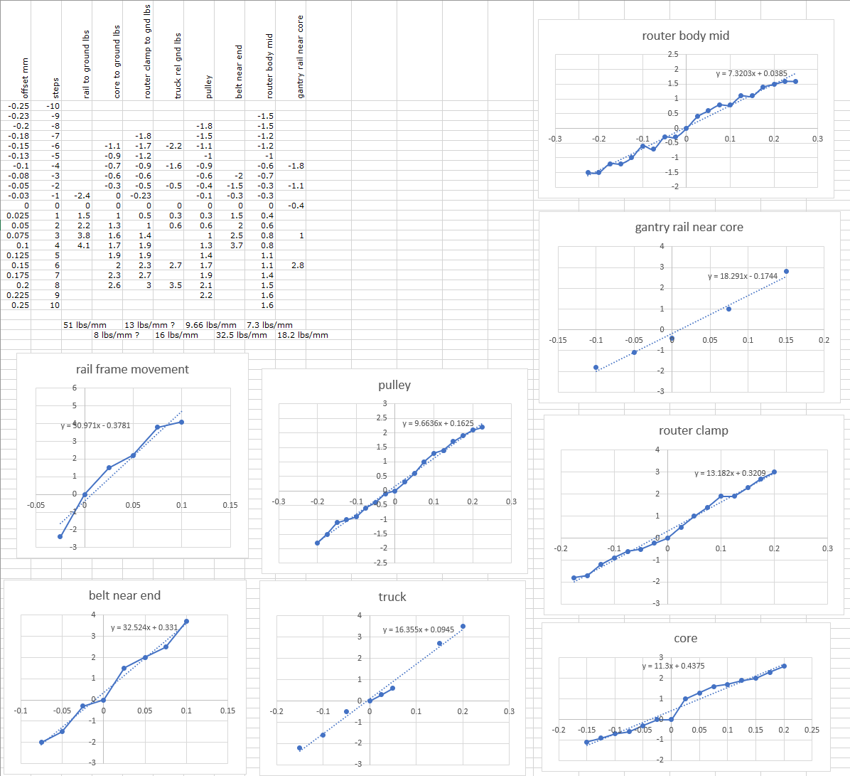
The bottom line answer is ~7.3 lbs/mm which is rather bad compared to what I would expect a typical Primo to be, and this is not the most interesting part.
I measured several other parts. With the machine near the center of the X/Y range and with Z near the bottom (about 11 inches below the core):
- Deflection of corners, where side rails meet legs. I have long legs and they might rack.
- Movement of belt near the corners. I’m not using zip ties but the attachment of the belts to the corners could deflect significantly.
- Movement of the trucks. Includes deflection of corners, attachment, and belt stretch.
- Rotation of the pulley wheel. With the knobs I have attached, I can see the motor pulleys rotate a slight amount when loaded.
- Deflection of gantry rail near the core. This will be very similar to truck movement but also include lateral bending of the gantry rail.
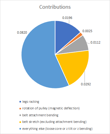
The corner movement is not insignificant. About 0.020 mm/lb due to having long legs. With short legs this would be much less of an issue, and I would guess about 0.005 mm/lb or less would be more typical.
The belt attachment is about 0.011 mm/lb. I think this is probably better than zip-ties but worse than the Primo design. I’m not sure what to guess on Primo. A long time ago I was puzzled by belt stretch measurements that were inconsistent depending on how I made the measurement. I think the cause was the attachment deflecting, falsely causing the belts to seem stretchier than they really were.
The belt stretch (for my 1.13 meter belts) is 0.029 mm/lb. This is pretty close to the predicted value of 0.022 mm/lb using the belt stiffness I had measured years ago. On Primo with 10mm belts and a more reasonable size of say 24 inch belt length, this would be closer to 0.014 mm/lb (at edge supported primarily by one belt) or 0.007 mm/lb (at center when supported equally by 2 belts).
The lateral deflection of the gantry rail is less than I can measure. I am using thick-walled (0.12" wall) 1" tube and the deflection of the gantry rail measured very slightly less than the truck movement, which is almost certainly a measurement error.
The rotation of the motor pulley is measurable with a long enough arm to indicate rotation, but the value is very small when calculated back to its contribution to overall deflection. It contributes 0.0025 mm/lb.
A bunch of contributors are broken down to components and everything else is allocated to core deflection or Z-axis tilting. If the core were to have a loose grip on the Z-axis and it could shift laterally, or if the upper core were loose and the Z-axis could tilt, or if the Z tubes could bend, those could all contribute to the router deflection, and I haven’t measured those separately. Those are going to be unique to my setup so they are not informative for what most people will experience. All together they contribute 0.082 mm/lb, which is more than half of the deflection.
To reiterate, legs racking on my machine is probably 4x worse than a typical machine, and belt stretch is between 2x and 4x worse than a typical machine with 10mm belts. Belt attachment I’m not sure, but probably much better on Primo, so I would expect a typical machine to be maybe roughly 0.025 mm/lb total for deflection excluding the core. That might not be saying much if the core is the dominant contributor, but it’s a good foundation.
4 Likes
That is some amazing detain, Jamie.
I must have missed something though. How are you determining where the error is coming from?
And how can we get you a “standard” primo to test against? ![]()
1 Like
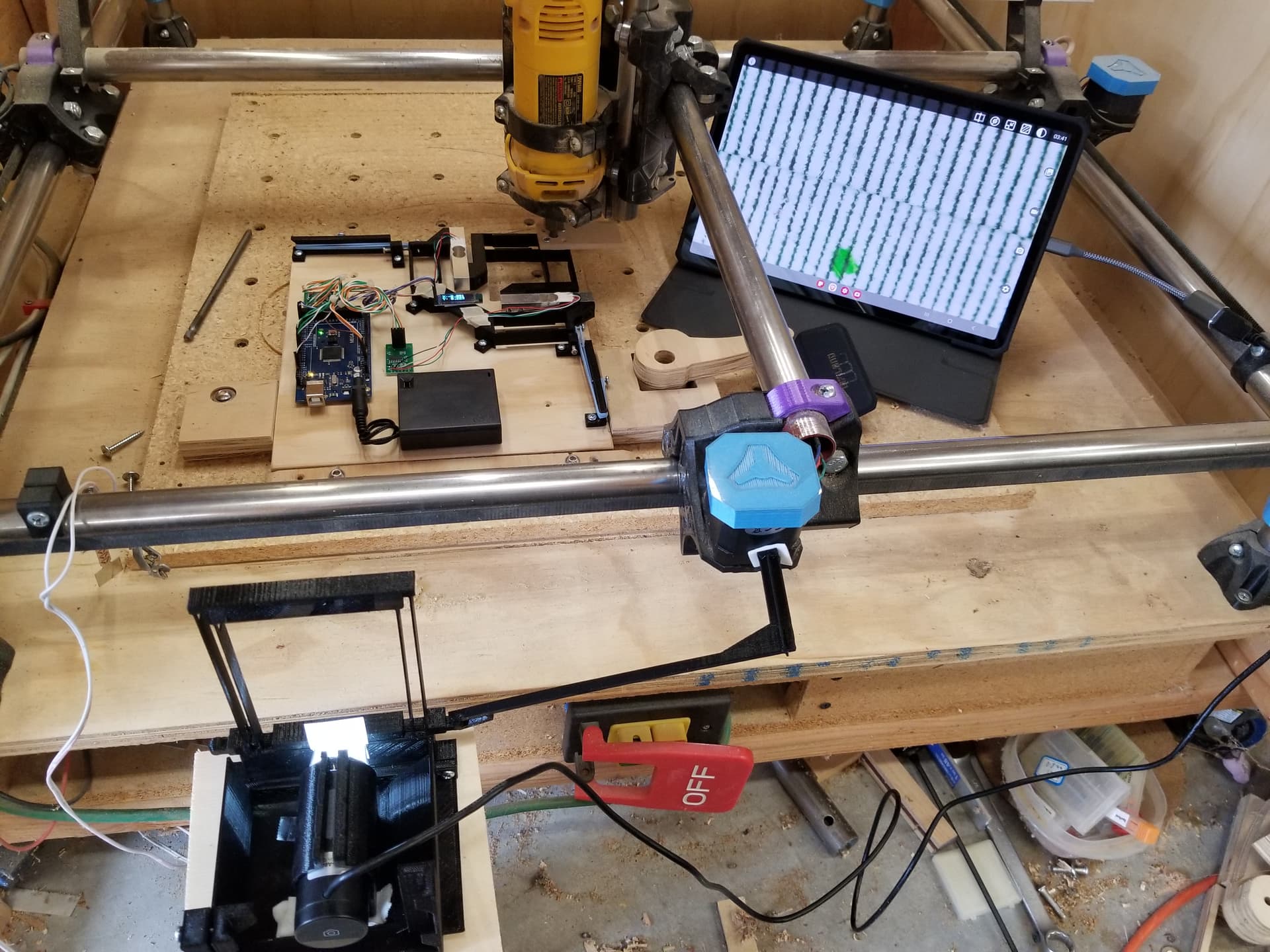
Currently I am applying a tracking sticker on a part of the machine and using my phone zoomed in to watch it move while I apply force. With a phone tripod resting on the table, I’m measuring the movement of that part of the machine relative to the table while applying a known force to the tip of the router. The difference in stiffness between point A and point B is attributed to deflection of the parts between point A and point B.
If trucks move 0.0625 mm/lb and the end of the belt moves 0.0308 mm/lb, then belt stretch (and pulley rotation) accounts for the difference of 0.0317 mm/lb. If the end of the belt moves 0.0308 mm/lb and the corner piece moves 0.0196 mm/lb then the belt attachment is stretching/bending 0.0112 mm/lb. And so on.
It’s rather janky and getting fine measurements is not as reliable as I would like, but the optical measurement allows me to measure anywhere, unlike the dial indicator which requires some room and also requires pressing the plunger with maybe an ounce of force. That’s a problem for e.g. measuring the movement of the belt near the attachment point, whereas optical tracking of the sticker is much simpler mechanically.
I’m trying to think of better ways to measure movement but so far all I have are concepts.
As for measuring a decent Primo machine, I’m going to invite myself over to David’s house. What are you doing Saturday @niget2002 ? ![]()
3 Likes
Kids have a piano recital at 11 to 1, but Sunday afternoon is free ![]()
3 Likes
What app and tracking marks are you using for the phone and sticker measurements?
1 Like
I printed myself some 0.5 mm scales and 0.525 mm scales on a laser printer for a home-made Vernier scale with 0.025 mm units. One of the scales I attach to the phone for reference using a 3D printed bracket to hold the scale about 3" in front of the camera. The other scale is attached to the machine. I read it by eye using the phone as a magnifier with no software.
As janky as it is, since I can physically see the machine move, I have some faith that the data isn’t complete garbage. Each data point might have somewhat lower accuracy but the aggregate linear fit should be okay.
Maybe with a flexure that includes a lever or something I can amplify the movement and read it without a magnifier, so then no phone would be needed.
3 Likes
The results from David’s Primo are in, with a couple improvements to the methodology.
One, instead of a phone camera, I used a USB microscope and an OTG viewer app on a tablet, which affords a better illumination and better view. A unlike the phone, it doesn’t time out and go back to the home screen, at which point touching the phone can disturb the measurement.
Also I have a new extremely-compliant mechanism that allows one dimensional movement only, and a push-rod to move it, which is much less janky than what I was doing before.
I tried for a mechanical means to amplify the movement but that was a bust, so I am measuring at 1:1 scale.
One of the things I learned is that the spacing between the lines is uneven:

The spacing in the SVG file in Inkscape is of course perfect, and I rotated the artwork at an angle, assuming that would prevent any aliasing effects and the resulting edges would be perfectly spaced, but I was wrong and the pitch came out uneven. This has a big effect on the Vernier readout for individual increments but smoothing over multiple increments reduces the effect.
The results:
The movement of the corner block and belt near corner were too small to measure. I applied only about 3 lbs (and -3 lbs) and the movement was less than 0.025 mm which would put it at less than 0.01 mm/lb. Maybe much less. I don’t know.
The movement of the truck was 26.5 lbs per mm, or about 0.038 mm per lb.
I also measured the Y gantry rail in the center near the core, and the deflection was 19.3 lbs per mm, or about 0.052 mm per lb, which is slightly more deflection than the trucks and would imply 0.014 mm per lb of horizontal deflection of the rail. This is 1" stainless steel.
I also measured the Z rail just above the core (about 75 mm above the Y rail) and the deflection was 0.035 mm per lb. Deflection of the Z rail just below the core (about 100 mm below the Y rail) was about 0.089 mm per lb. This is inclusive of the lateral rail deflection and the core tilt by itself would be -0.017 above the core and 0.037 below the core.
So to summarize:
- Negligible deflection from corners and belt attachments
- 0.038 mm/lb from truck movement (belt stretch)
- 0.014 mm/lb from gantry rail bending
- 0.037 mm/lb from core tilt
- 0.089 mm/lb total from above 3 sources
At first I was trying to hurry so as not to impose on David, but I eventually figured out that he was having a leisurely afternoon, and we had a nice chat. Thanks, David for being such a gracious host!
7 Likes
Even though there are lot of numbers, I understood the results. Pretty neat to have a benchmark on deflection. Thanks guys. ![]()
1 Like
This is really nice! Well done!
Yesterday I stumbled across some Youtube videos from Brian Howard (link) where he uses a laser level and a cheap webcam to measure flatness with an accuracy in the single microns.
I tried it myself with a $25 laser level from Aliexpress and a $10 USB webcam (Trust Trino HD). I tried to use Brian Howard’s software (github), but I ran into some version issues with Python so I used the linked Java program. It seems to work very well indeed.
This method can also be easily adapted to measure deflection, as long as you can mount the webcam to the part you want to measure and the maximum deflection is smaller than 2mm or so. The software makes it very easy to make measurements for different loads and compute the final mm/pound numbers you’re looking for.
5 Likes
That is cool. I wonder if there would be a market for that if you made a mobile app and sold the cameras. The accuracy is pretty insane. I am not sure how often people need that much accuracy vs wanting a larger range. But I bet there are at least 10k people that would pay for a tool like that in their shop.