I’ve been kicking around the idea of building my own take on a CoreXY printer for a few years now. I’ve looked at many of the existing options (HyperCube, VzBot, HevORT, RatRig, RailCore, Voron, etc etc) and have read through a lot of build blogs for other personal projects (Like Mark Rehorst’s UMMD). The end result of all that reading is that I decided none of the existing designs quite scratched this particular itch so I went about designing my own take on the CoreXY printer while incorporating as many “clever” ideas that I have gleaned from other builds as possible.
Here is a (non-exhaustive) list of aforementioned clever/bad ideas:
CoreXY motion
Frame does not rely on carefully cut and assembled aluminum extrusions
Parallelism of the critical belt-sections is not dependent on very precise assembly of frame/motion components
Belt-path will avoid cantilevered belt pulleys as much as possible.
Entire build will not rely on extremely high-tolerance parts of any kind (save the ubiquitous “MGNX” linear motion components).
Rely as little as possible on structural printed parts.
Eschew toothed/smooth idler pulleys for stacked sets of flanged bearings (taking a page out of the Voron playbook).
Use an ultralight carriage (Sherpa Micro extruder and very low-profile/weight accessories, or a bowden extruder) to allow the use of an unsupported (or minimally supported) X rail.
Utilize Klipper Firmware (with input shaping) to loosen the requirements on axis rigidity somewhat.
etc. etc. etc. (but that probably covers most of the “big ideas”.
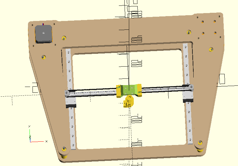
Taking all of that into consideration the end result is something close to this:
XY motion is via three linear rails (Y is MGN12, X is MGN9). All of the pulleys are pairs of F695 bearings (like the Voron 0). Pretty much everything is sandwiched between two sheets of 1/2" MDF so all of the motor mounts and idlers are supported at both ends (nothing cantilevered). The XY pulleys are stacked on a single M3 bolt (with 5mm bushing) rigidly connected to the Y rails (and the X rail is rigidly connectec to the two X rails. Those are not cantilevered, but being rigidly attached to the steel carriages they shouldn’t be prone to ‘creep’ like a printed part. The ‘critical’ CoreXY belt sections are kept parallel with the help of eccentric pulley idlers at the four corners providing +/- 2mm of adjustability to make sure things are lined up even if I end up drilling the holes in the plates by hand. I’m still playing around with the carriage design but currently I’m trying a Sherpa Micro, Ender-3 style hotend, and a part cooling fan.
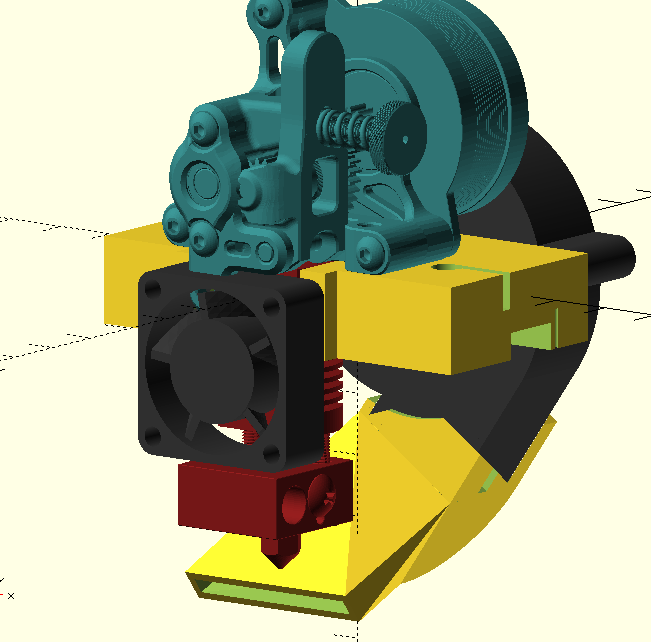
Here is a recent render of the X carriage. The fan duct is being reworked to actually cool the part without crashing into it and the rear blower fan has been relocated.
The top and bottom plates are ideal candidates for cutting with a CNC router but the MPCNC I built doesn’t have a sufficient build envelope and the LR2 I’ve been “working” on for a few years is not going to be cutting anything soon .
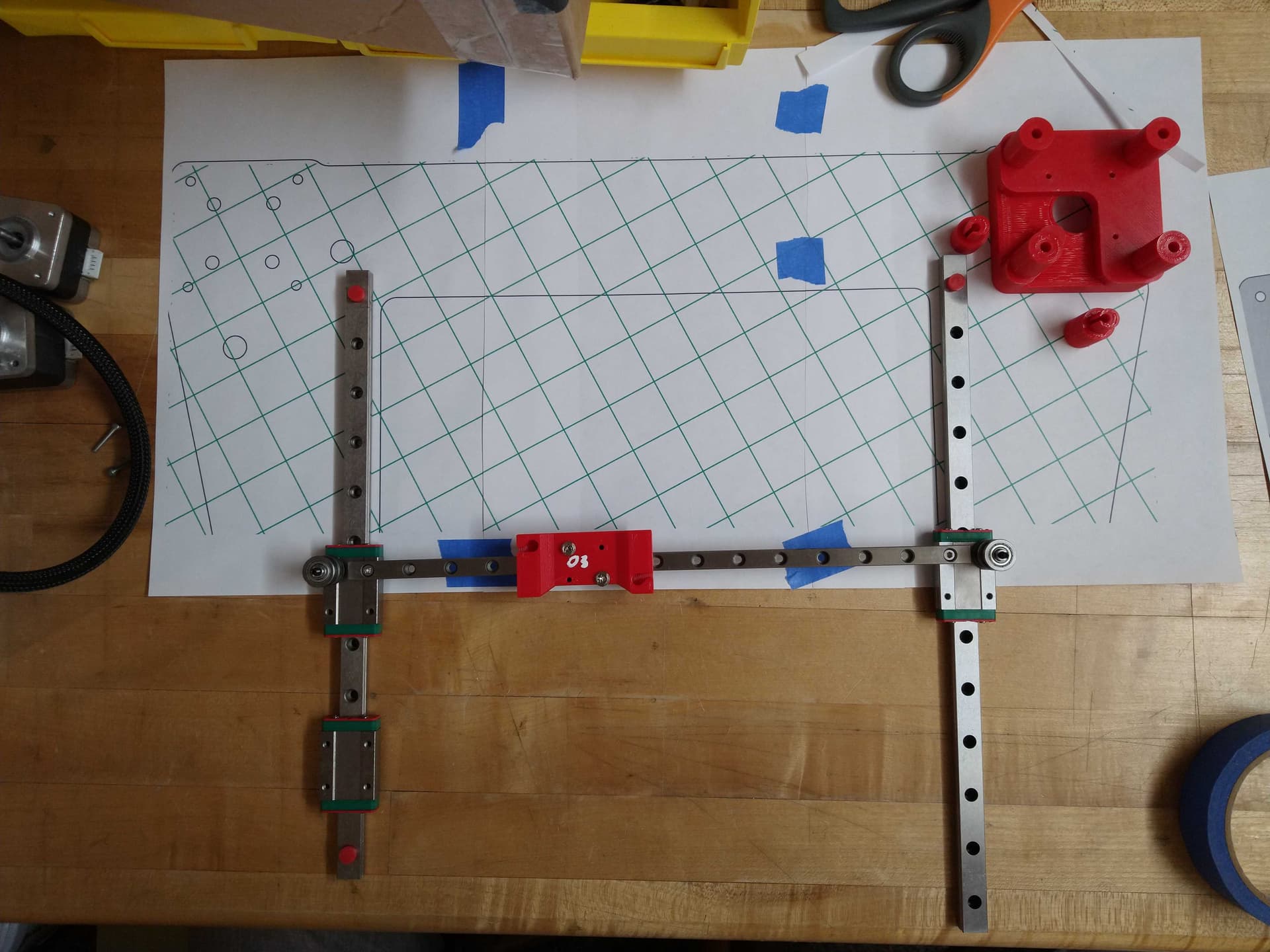
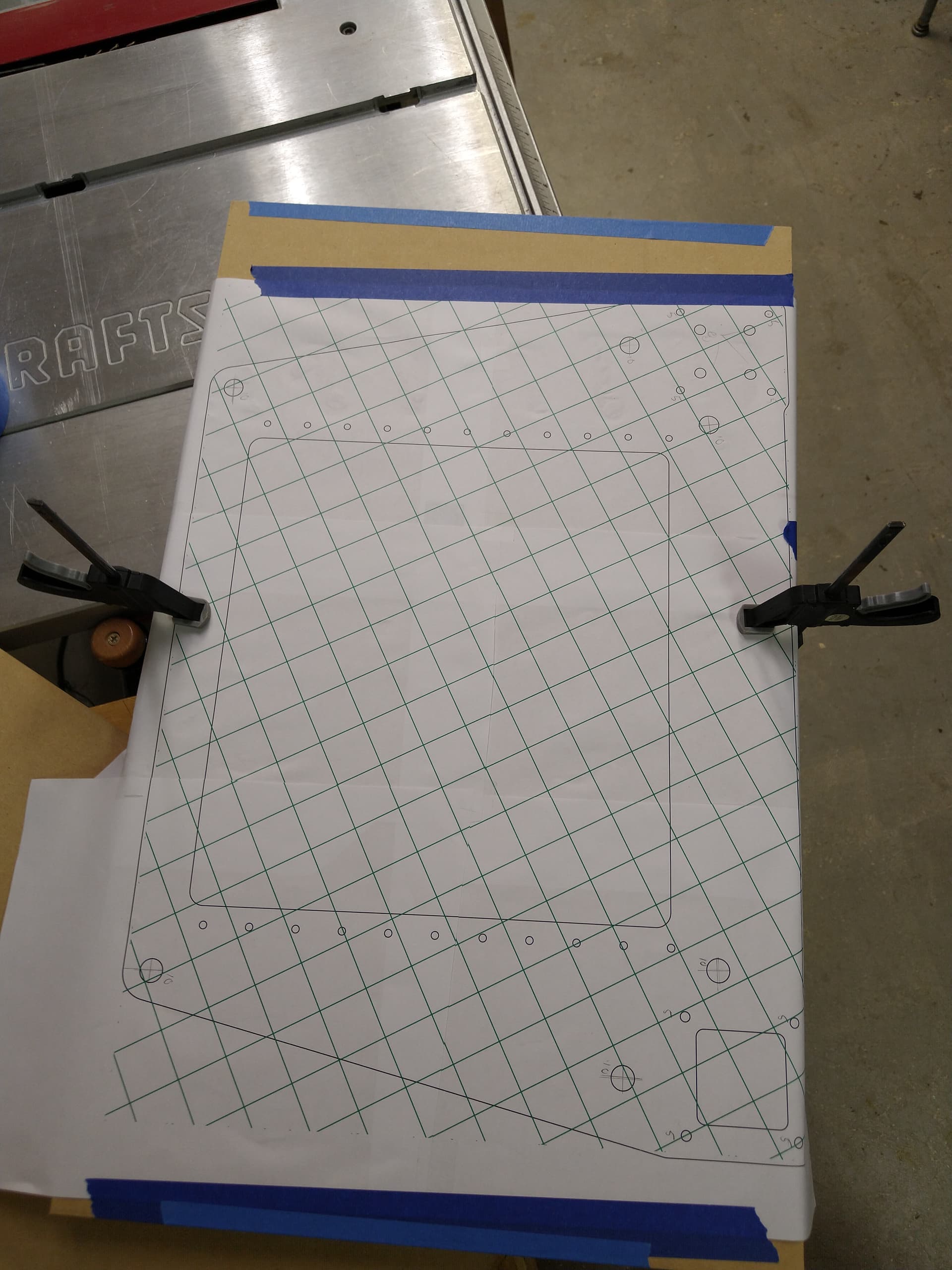
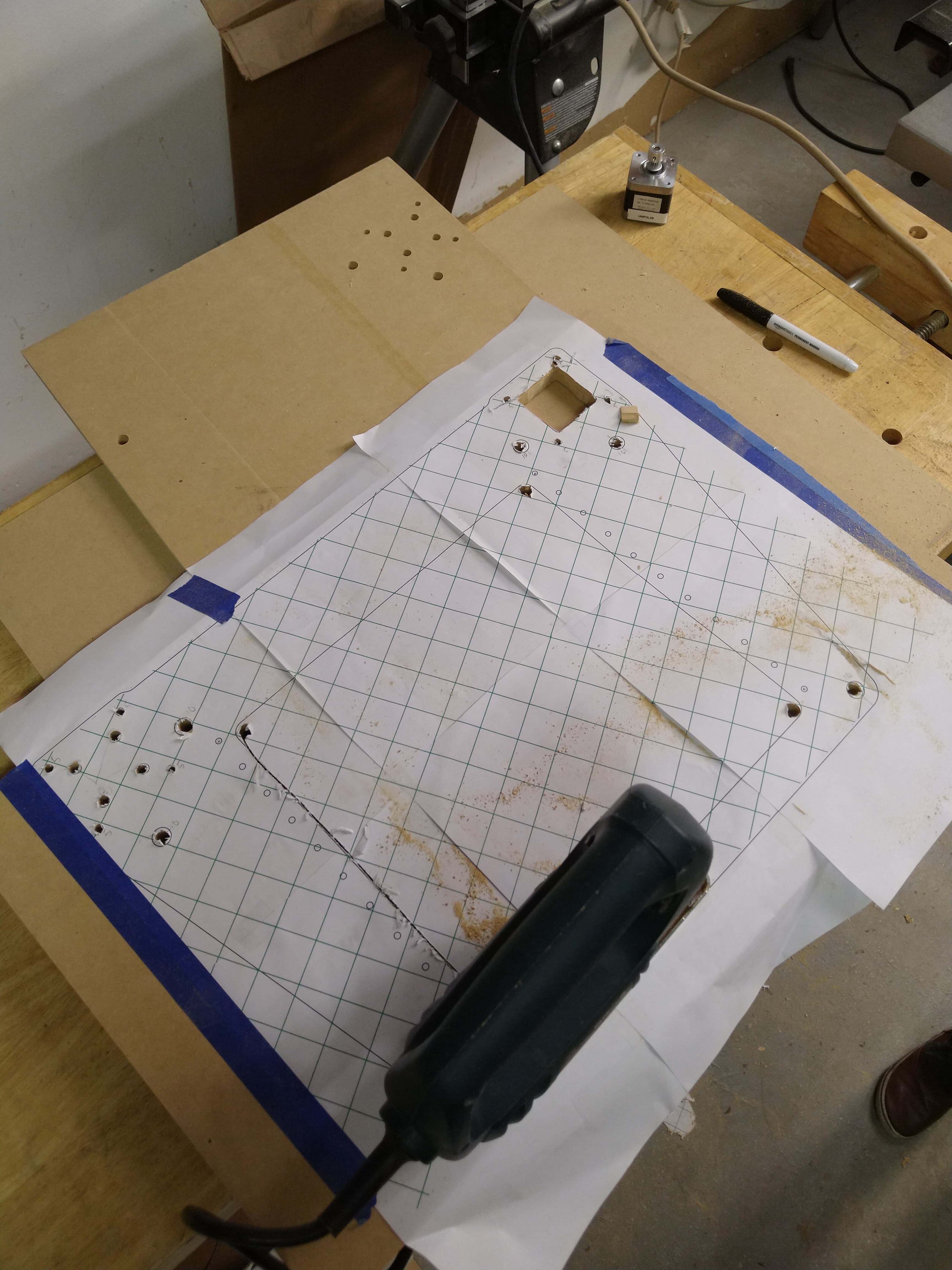
So I’m doing that step “Matthias Wandel” style by printing out 1:1 paper templates which I can stick to the MDF sheets before cutting to shape with a jigsaw and drilling out with a drill press.
I used Inkscape to export the SVG of the DXF of that plate as a PNG (adding that green grid to aid with alignment) and then used PosteRazor to print it on several sheets.
I can tell you I am already to redesign the repeat. I have been exhaustively tweaking the repeat for accuracy, and I have learned a ton. CoreXY is not easy to get “perfect”. I highly recommend you throw one together in extrusion first. The level of accuracy needed on all the rails you use is nuts. A working printer is super easy to build. An accurate printer is not. One of my rails was 3mm off. I run a CNC company and I obsessively check for accuracy during the flat part cutting. Best I can figure is wood moves, and assembling a perfectly perpendicular box is not easy to do. Keep this in mind, if one rails is your reference, how will you set the rest? Not just parallel, parallel and planar, then some need to also be perfectly perpendicular.
Even if you have a great box when you mount the rails they all have some play (hint) do not use every screw). So even just screwing the rails in to perfectly cut holes, they have considerable play (0.2-0.3mm), at which point you hope it is enough to adjust to match the other 4 rails.
Build it out of extrusion and test large cubes for accuracy, then see where you need to build in adjustment points (hint everywhere).
The rail on rail you are showing is rad, I would love to try that extruder myself and your design seems awesome other than I would wrap the fan a bit more around the nozzle from other directions. Printing fast needs way way more cooling than I expected. You see some of those speed build have entire layer blowers…it is needed to go much faster than normal. I am cooling limited on my build.
Another thing that keeps effecting my prints is the extruder umbilical, and force there and it makes the nozzle dive 0.1mm or so…not cool. I want to try something like this, https://www.pandapi3d.com/product-page/pandacan-extruder
I am following along, hopefully you work this out before I have time to start on the repeat redesign.
Yes, indeed. I’m building the XY motion on a slab for that very reason. MDF is reasonable flat/stable and if it is a continuous sheet then it can’t rack. Adding the second sheet to the top sort-of makes it into a torsion box which should help with keeping it planar. If I needs more stiffness I can add more material between the sheets.
I’ll cross the square/parallel bridge when I come to it but my initial plan is to set one rail as the reference, mount it, square the X rail via jigs/squares/trigonometry, and then use that to set the opposite Y rail to be parallel.
I had originally drawn the Repeat that way as well planar XY. I am very interested to see how you tackle some problems. I have so much fun with these, I love looking at other solutions.
Have you tried that extruder yet? I might have to get one to check it out.
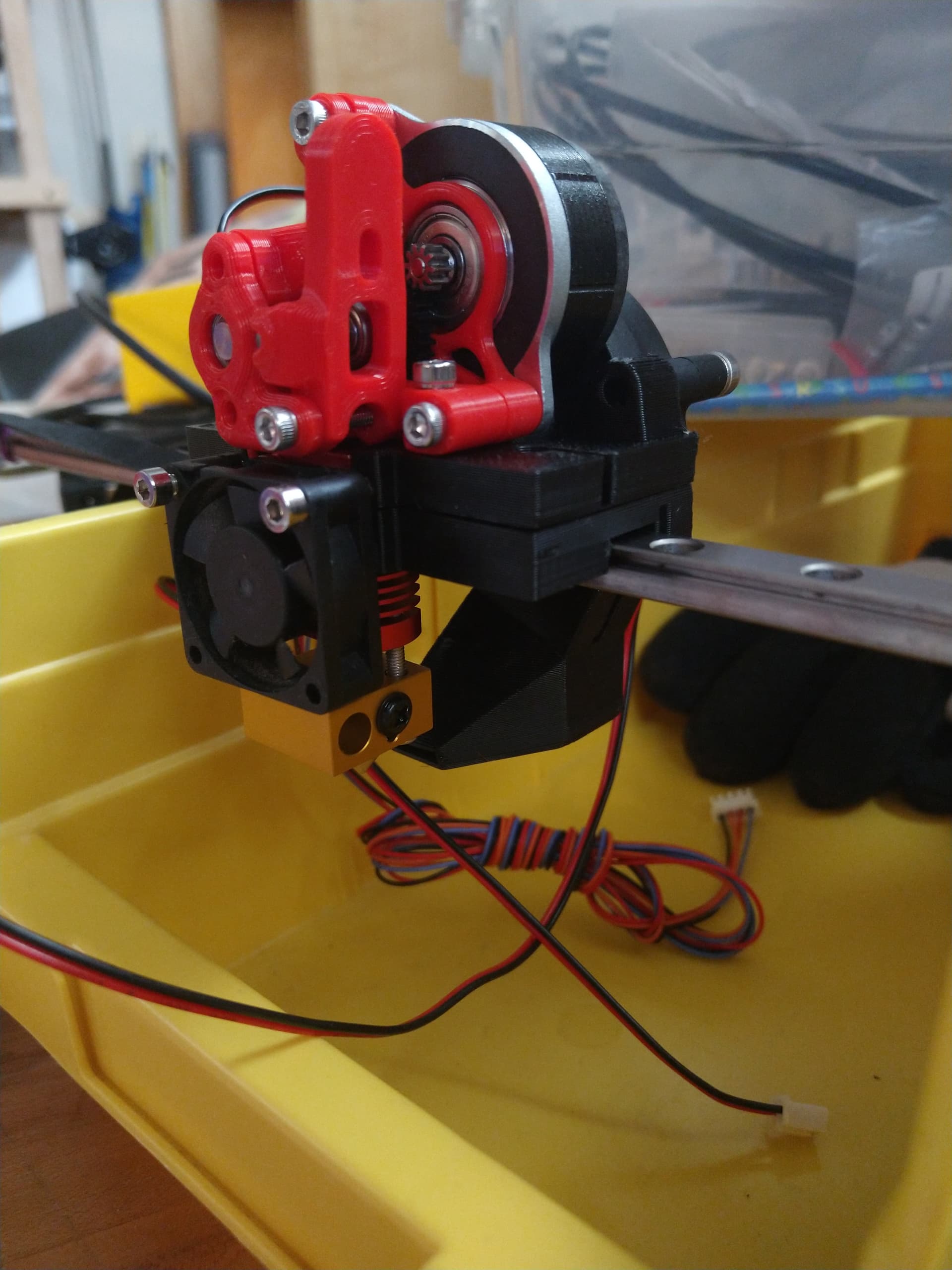
I’ve printed out one in PLA as a stand-in for prototyping (they recommend ABS/ASA for the real thing) and bought a parts kit off AliExpress. Here is the current state of the carriage:
There are some cool ideas packed into this. That I’ll point out in a bit.
For reference: The Timber Bot I built is still going strong. I built it when I lived in Colorado. Where it was never humid unless it rained and even then it was super dry again within a few hours. So now that I live in Missouri where it is more humid 54% in my office right now in May and it will hit 80% in the summer. With that said I am glad that I chose plywood to build it. It doesn’t seem to warp, expand as much as I was afraid of.
The only problems I have had with it were self inflicted. I messed up my acceleration & Jerk settings in the pursuit of speed. But other than that everything I print on it is as precise as my Prusa MK3. So I am VERY happy with the precision. My choice of print bed was crap. Its an old recycled 210 x 160 mm from an old Davinci 2 Duo (made by XYZ Printing). I like the small size because it creates less heat waste in my office when I am printing small items. But I WISH I had a magnetic steel sheet for it.
I have NOT built the other 4 Timber Bots I planned to for the same reasons both of you are discussing here. I want to change it all up.
I really like the idea of using the smaller belt idler bearings. I am not happy with the 608 bearings and I want to change those. I really like the idea of of bolting those idlers to the rail truck. I am worried that you may bend or break that 3M bolt when the belts get a little tension on them. But maybe if you spread the load onto more bolts using a flat piece at the top?
I like the two pieces of wood sandwich/torsion box for the XY plane. I have to wonder how that will play with the sound from those steppers. Will it help contain it? Direct it? or will it turn the box into a speaker box and make them sound louder? Even with mine in the back of the box they are louder than I expected. And that is even with Duet Stealth Chop. But still that double wood thing could be nice if you get all the mounting holes lined up perfectly.
What size of rail are you using for the X? That isn’t an MGN12. I really like the idea of using that smaller, lighter rail and having it bolt directly to the Y trucks. How much flex does that rail have?
There are several good options for flanged bearings out there. Toothed belts on flanged idlers do best with wider radii than what the F695 bearings deliver (14mm) but I had a tube of 50x of them and their size made my direct-mount-to-rail X axis work.
Those bearings have a 5mm bore so there is a 5mmOD (3mmID) brass tube in there as a bushing. a washer at the top clamps the shim washers and the inner bearing races down so the effective diameter of the post is something like 8mm so the little 3mm stud in the center is not seeing too much torque. That is the theory at least.
MGN9 rail for the X axis. MGN12 was the original choice but that left too little clearance between the rail and the belts. I haven’t done any flex measurements so no idea what that looks like. If it is bad I have some 10mm square aluminum and CF tubes that I can mount the rail to for some added support. If the extruder assembly I have now (150ish grams) causes too much flex I’ll probably pivot to a bowden extruder for the short term before trying anything drastic.
I’m thinking more about the possibility of the axis binding with changing humidity of by diffferential expansion of materials when things get warm up. The alpha test machine will be straight to the MDF because I have to just get something built to figure out what does/doesn’t work. I’m thinking up some ideas about how to make one Y rail the “authoritative” one and allow the other to ‘float’ a bit without letting things get out of square/plumb…
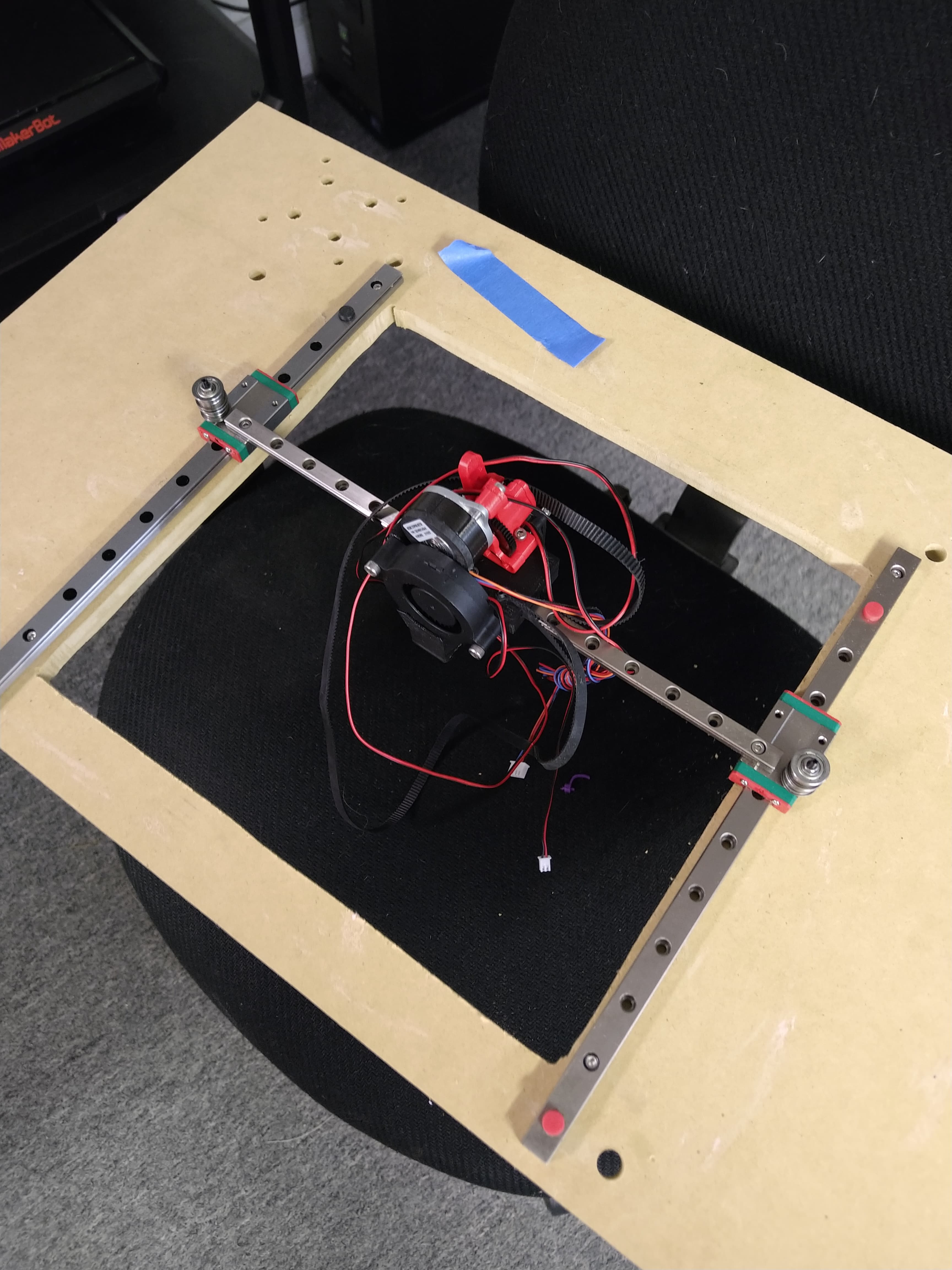
If things work out I might be cutting my first plates for this machine at the local makerspace tonight.
And then installed the rails and tried to get things square/parallel. I need a better squaring aid than a 4" machinist’s square.l but things appear to move smoothly.
The eccentric bushings that I printed were a bit oversized in the 10mm bores so that was as far as I got. After I reprint (or sand down) the bushings I can attempt assembling the plates and route the belts.
Thanks. Going through this whole exercise (on “paper” for the last few years, and now IRL) has given me a lot of time to pick up “interesting” ideas. The biggest thing I’m discovering in my additive manufacturing (and CNC in general) adventures is to get a really good grip on the actual requirements/constraints that exist for the project and focus only on meeting those and let the rest sort itself out as you go.
I was initially going to build a CoreXY motion with CF tubes, teflon impregnated bushings and a lot of complex printed parts to hold things together (but still using the MDF ‘sandwich’ concept). I couldn’t come up with a good way to hold the tubes, adjust the tube lengths, hold the tubes parallel/perpendicular, etc. and I couldn’t really make any progress. Also, there were two components (x and y rods) that I needed to keep parallel/perpendicular/coplanar instead of one which added even more unknowns into the mix. On top of that I was trying to use what is still a ‘novel’ motion concept which meant a lot of basic stuff was still unknown. Tech2C is the only printer I am aware of using round CF tubes and bushings so I know it is possible, just not very common.
Stumbling across the “MGN12 carriage hole as pulley mount” idea is what brought this project back to the front of my mind and things have been neatly falling into place thus far. As mentioned higher up the largest challenge ahead is to make sure everything is square/plumb/planar without the aid of very carefully cut aluminum extrusions.
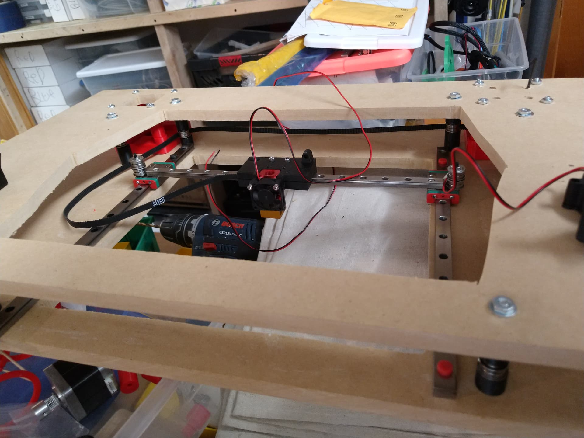
The parts are together, but it was a bit of an ordeal. I’m pretty sure I flipped the top plate before cutting out the motor hole so now it is flipped and causing some slight misalignment of the plates. The holes are symmetric but I cut them out with a pattern plus drill press so they may be +/- a bit. I mounted one of the motor mounts upside down, and trying to do all of this with the carriage and rail flopping around is pretty annoying.
If possible I would add a small brace to the pulley stack on the bearings. Like a little angle bar or something.The CoreXY belt get a bit more tension and a lot more acceleration tension than normal.
I’ve currently convinced myself that a brace for the pulley stack is a YAGNI item and will revisit that determination if and when it becomes an issue.
As it is I have a whole pile of even more questionable decisions validate .
After straightening out the motor mount issues I was able to route the belts. I somehow cut one of the segments too short, but had enough left on my roll that I was okay (another 10m of emergency belt is on the way just to keep the stockroom full).
Can you summarize for me the advantage of the flanged bearings vs. the pulleys? I read the referenced post and didn’t find it. I’m not opposed to the flanged bearings, I just don’t know what the purpose is.
The short-version is that the tiny little bearings in the aluminum idlers are crap (especially for the $ premium you are paying for them). Flanged bearings are cheaper and (likely) higher quality than the common idlers available from the usual scumbags. I bought 50x F625Z bearings (which make 25x idlers) for something like $8.
An argument for the aluminum idlers is that toothed belts on smaller smooth bearings can cause artifacts, but the popularity and performance of the Voron printers sort of disproves that. A Voron 0 uses F695 bearings and the Voron 2.45 uses F625 I believe. Even consulting official documentation (from Gates for their GT2 belts) they say smooth idlers are find if the pulley diameter is >= 40t is acceptable. I believe the F608 fits that bill if you are really concerned. Perhaps the other argument is that the small flange (only 1mm) on the bearing may allow the belt to escape. That probably isn’t a concern with relatively short belt runs, but for a large machine (LowRider, or a Large sand table) it is something to keep in mind.

 .
.

 .
.