Is using a motor instead of a simple servo for controlling the Z-axis a better solution? What does it imply in terms of modifications?
I’m in the design phase of a CNC laser/plotter machine. I initially thought I might encounter issues with servo control via an MKS DLC32 (apparently not the case anymore), and I’m considering replacing the servo with a small stepper motor … it’s better ??
“Better” is going to be an determination based on your specific need. They both have pros and cons.
How much travel do you need? Assuming by “small” you mean hobby-style servo, the servo will be more reliable and repeatable in positioning as it includes constant feedback within the servo, but will be limited in how far it can move, and in general can’t move as large a load (but this is dependent on the size of the servo). Steppers are easier to build a lead screw or belt drive around for longer motion, but are (again, generally) open-loop, so they don’t have the positional feedback.
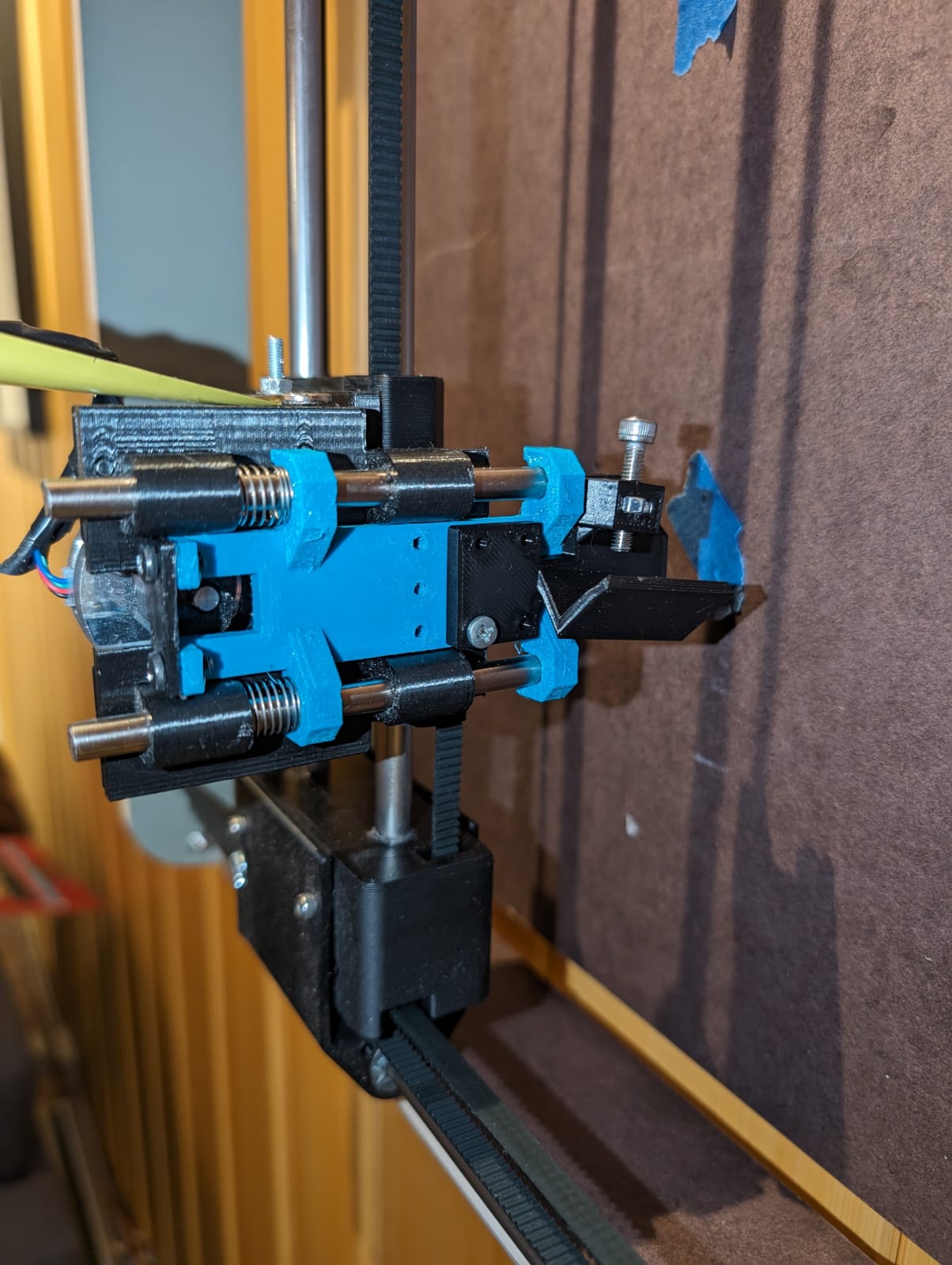
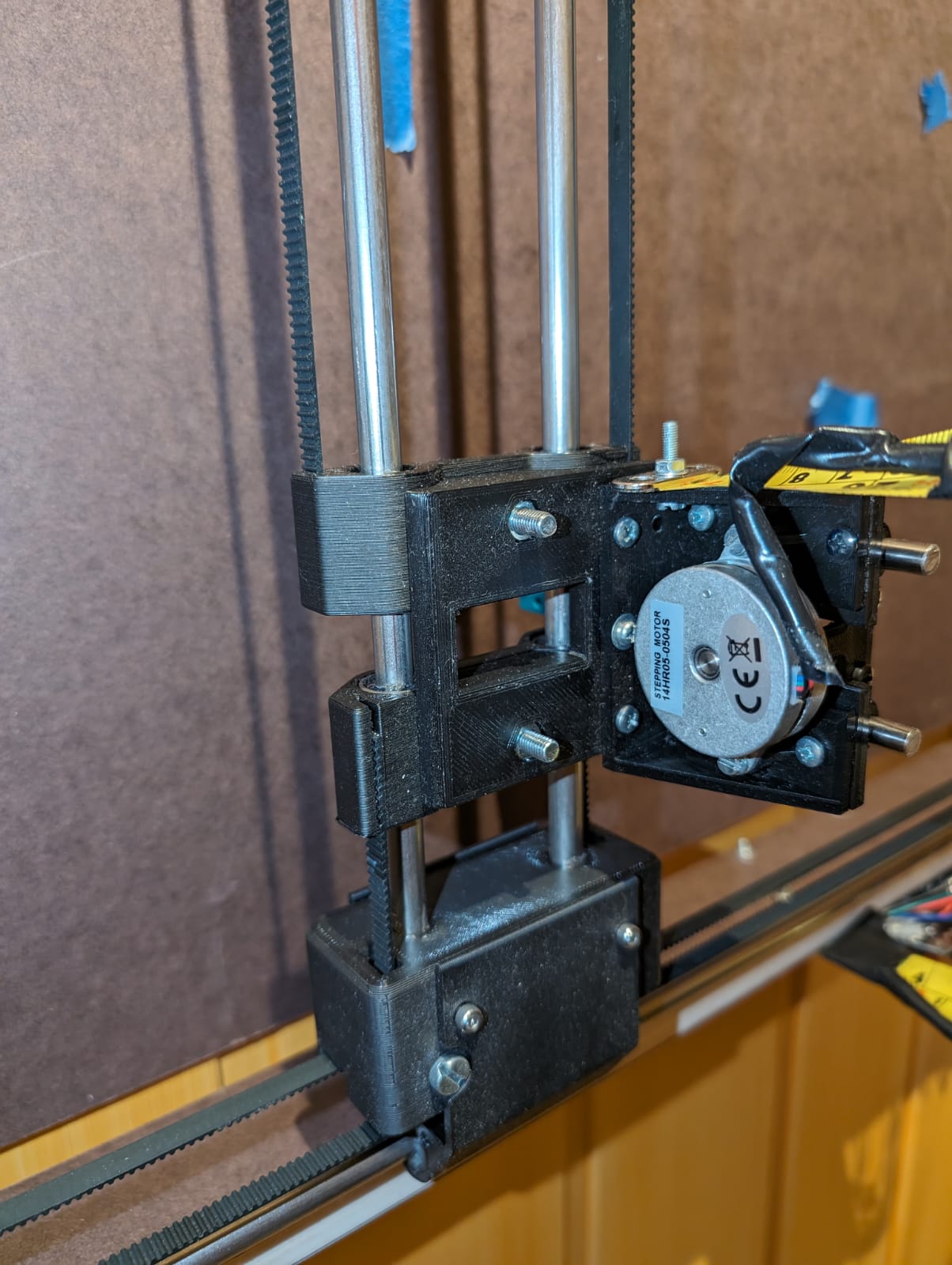
I’ve struggled with getting a reliable behavior from the smalls servos. Therefore I went with a flat nema 14 as pen lifter. Works like a charm, I’m very happy with the plotter now.
I need to study this solution further for my future plotter.
Besides replacing the servo with a flat NEMA 14 motor, what other modifications need to be made? For example, in terms of the G-code?
This comment worries me… I am in the process of designing a plotter that I would like to push to its limits, with long and fast plots without heat problem.
I am already considering adding fans to my stepper motors to cool them down.
Well, it’s still a long way for me; I am still in the design phase.
Note: This is my 4th attempt. The first two were complete failures, and the third one is 80% satisfactory. However, I encountered an issue with a A4 workspace; I ended up with a smaller one. Additionally, I have the problem of motor overheating, which is quite bothersome for me, even if it might be normal
This is one reason we changed to the rambo from ramps. The rambo has integrated digipots to adjust the current. So does the minirambo and the skr and jackpot (with tmc drivers). Those little screws are a pain and people would often skip it or short something when they slipped.
For reference though. My CNC machine current is set to about 900mA and the motors are fine. My ZenXY table (which drags a magnet under the table to move a ball through sand above the table) is set to less than 250mA. A pen plotter should be fine anywhere in that range.
If you are designing your own machine, you need to be careful when you design in your steps per mm. That is based on the rpms per mm and if you want to move fast, you need to gear up. We use 16T pulleys and GT2 belts. That results in speeds around 50mm/s comfortably. If you go with 20T pulleys, you will be able to easily go 20% faster, but any friction is 20% stronger. Steppers have less torque at higher rpms (they are complicated, but that is basically true).
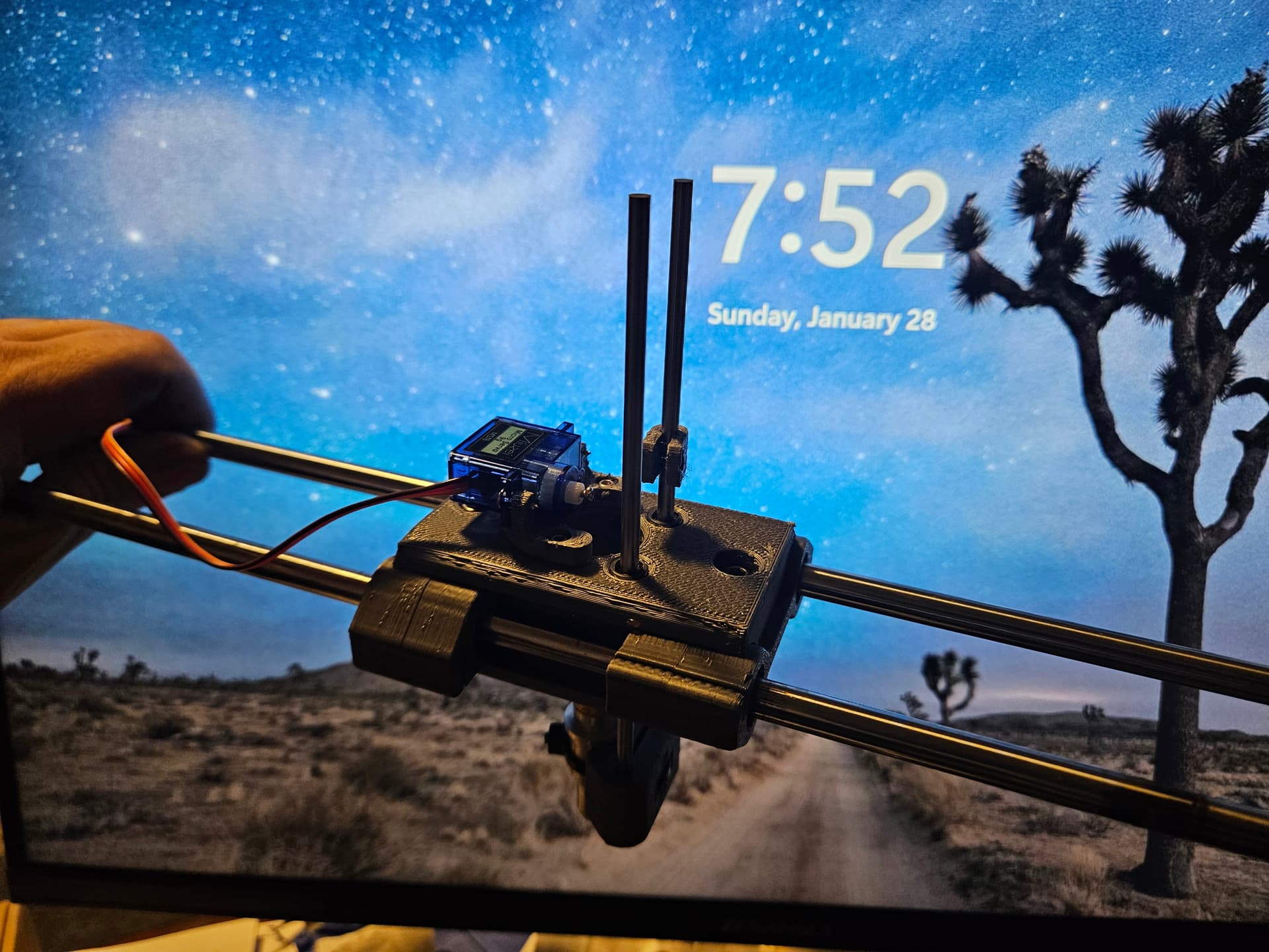
I finally put FluidNC on the Bart Dring 2209 pen/laser board V2, and giving it a shot for CoreXY motion and a servo for.Z axis. (Since the board only has 2 stepper drivers, a servo is the only real option I have for Z unless I change hardware. This is still a possibility.)
Given that the new purpose of the machine will be vinyl cutting, I expect not to need more than a couple of mm Z travel.
So I think that the D3 pin for the servo is on GPIO 16 from the schematic, but haven’t really tested it so far.
It’s a bit weird, because it seems to not really know its position.
$HZ seems to take it to it’s top position, but it doesn’t know what that is. Maybe the mpos parameter in the config.yaml would manage that? Dunno. It has the travel set to 5mm (seemed to be suggested for servos.)
In some test code, it seems consistent if I use
$HZ
G92 Z4
as start code. I chose the 4mm arbitrarily, since if I am using estlcam, I typically use -1mm as an engraving depth, which would work for vinyl cutting, and I have the clearance plane set to 3mm. That gives me some freedom to set the servo height a little.
If I don’t set the height, then wherever the servo happens to be is 0, and it sometimes then moves if I tell it to go somewhere, but then does not move if I tell it to go back to 0. FluidNC seems.perfectly happy to have the servo range be from 100 to 105, but then it gets lost if I tell it to move outside of that range. It then seems to set a new range, but I haven’t been able to consistently find it after. This worries me, because something weird in the CAM might cause problems, like if I tried using a carve from the LR or Primo to cut a stencil, an out of bounds movement might pull the knife through the middle of the vinyl. I’d much rather be able to define a range of motion for the servo (for example min_pos: -1 / max_pos: 4) then have the servo always go to its relative position in that range, even if commanded to go somewhere outside of it. Therefore G1 Z100 would move thr servo to the full up position and the machine would report that it is at Z=4, and then move it down 1/5 of its range if told G1 Z3 I think this would make a consistent and usable function, though I suppose that could have unpleasant consequences with stepper motor function.
Or maybe I should try with soft limits enabled on the Z axis… Or just use CAM intended only for this machine…
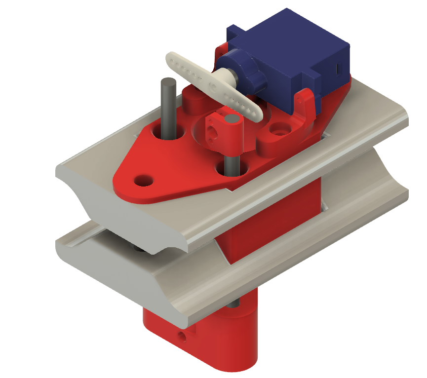
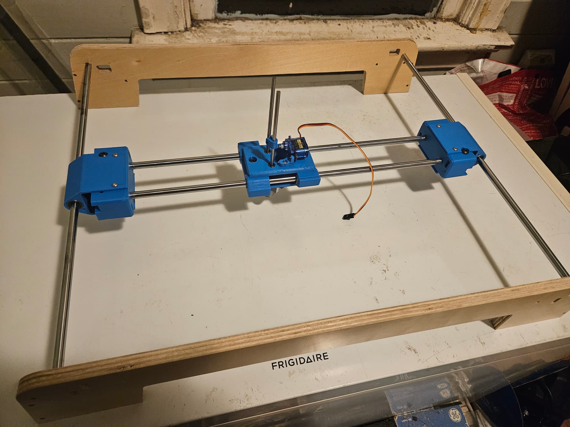
I had some 4MM rod left from the needle cutter project, and decided to try using it with some LM4UU linear bearings for Z axis motion. The servo holder is held onto the top with 3 M3x10 screws, and I could swap this for a stepper motor if it doesn’t work out easily enough. (I could probably even leave the drive similar, I suppose.)
downside is that I don’t actually have the LM4UU bearings, so I had to buy them, but I already had the 9g servo 4mm rods, and all the screws.
The plan is to use 1mm pushrod wire from the servo to the rod, which will serve as servo saver/spring for the drag knife to ride on the vinyl. I think it will work OK. The rod end is clamped down with an M3 screw. It should work just screwed into the plastic, but it’s so small it will be a cinch to use a nut. (It will also be a cinch to crush the plastic part, so … )
The process of designing this was made more complicated by the fact that I designed all of the original parts in FreeCAD, and this was done in Fusion360. I imported the sled STL model into Fusion360, and of course it came in a billion little triangles. There is a page or so of removing facets in the project history before anything else happens, and of course the curved portions are still faceted like crazy. I almost went back to FreeCAD for it, but stubbornness won out. (If I have to do it again though…)
It also occurred to me that I could make a needle cutter module for this as well. It would probably work out better than the one that I did for the LR, now that I know the LR mount had other issues which were contributing to the unsatisfactory nature of the finished cut. I thought it was the needle cutter’s fault, but the results that I saw with the laser on the same mount were kind of the same. I thought I’d used the drag knife with that same mount, but it’s still zip tied to the different mount that I made for it, so I guess not.
My 400mm rods are beyond redemption, but the 450mm Y rods survived. Well sort of. I had to scrape some burned plastic and belt rubber off of one of them, but it seems none the worse for wear. Two of the LM8UU bearings seem OK, but I think re-using them would be pushing my luck.
I forgot how tight those LM8UU bearing fit into the sliders. It’s a super tight fit, needed to use more force than I probably should to get them in. I may have to re-do them if the rods don’t slide smoothly. I think I boiled or at least heated them last time to soften them a bit. I just put the rails through the X bearings for the carriage assembly.
It occurs to me that I could probably just drop a pushrod down that center hole to the drag knife, but I still need some sort of servo saver to give it a bit of springiness.
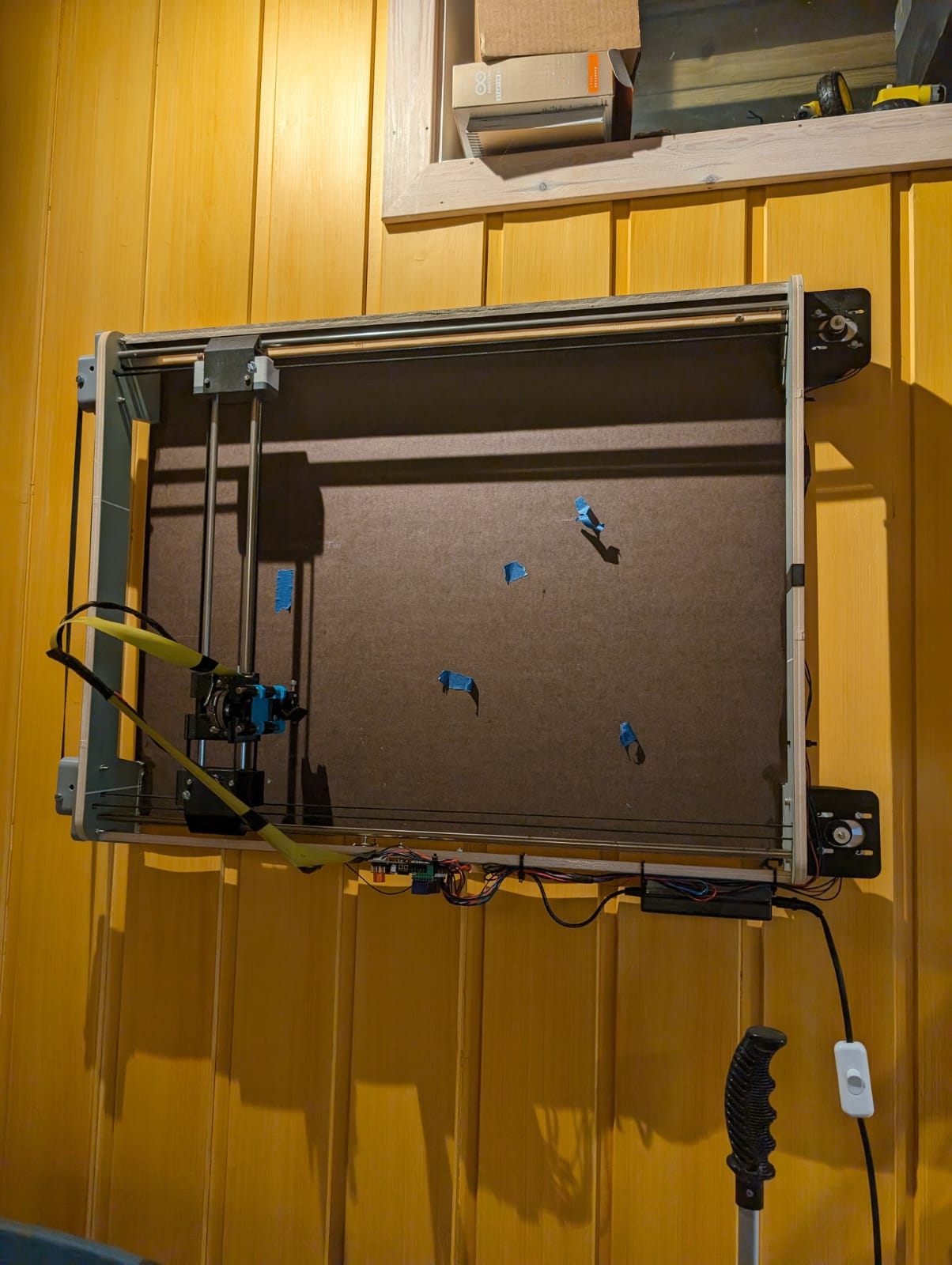
My biggest gripe now is that the current project I’m meddling with would work much better on a bigger plotter… I could use a new LR3 for it, but I want something to keep indoors and perhaps even on the wall.
That is a super fun idea. I have a drawing on my wall. The pen is fading slowly. It would be fun to have this with a drawing already chocked up. If a guest asks about it, I’ll peel of the old one, hand it to them, and then start plotting a new one. They could even sign the new one and the next person will have this weird connection to one of my other guests. So fun.
What is the “best” plotter build? If I want something as simple as possible, that can be hung on the wall, and that is reasonably fast and precise. The H-bot CoreXY is a very neat construction, but I don’t know what kind of build is the simplest in terms of construction and price?