I haven’t build the vacuum hold down yet (need to increase my table size first), but the one that caught my eye was 3 layers of DTFB and is documented in the This project really sucks. (Super cheap vac table) topic here on the V1 Engineering forums. The bottom has channels running the long direction of the foam, the middle had channels running the short length (90 degrees to the bottom), and the top layer had (I believe they were 1/4”) holes that lined up with the intersections. There is a 3-d printed manifold that tucks into one end to connect to a shop vac.
1 Like
If it helps here’s the onShape project from my vac table (the “This project really sucks” one)
Looks like I have the 3D printed plenum in there as well…though I didn’t design it myself:
When I made it I didn’t cut slots for the vac fitting - I just used a razor to trim out the spots where the 3D print fit in.
I kept trying to overthink the whole thing and thankfully @dkj4linux convinced me to keep it simple with his example.
I never even bothered with a way to attach it to my table - I realized that with the slots open on the bottom it vacuumed itself to the table just fine. So my big plans on a frame to hold it were completely unnecessary.
1 Like
My DTFB vacuum “stack” is the same as Jason’s. I think we co-developed it over on the FliteTest forum… described here.
Turn down your sound…

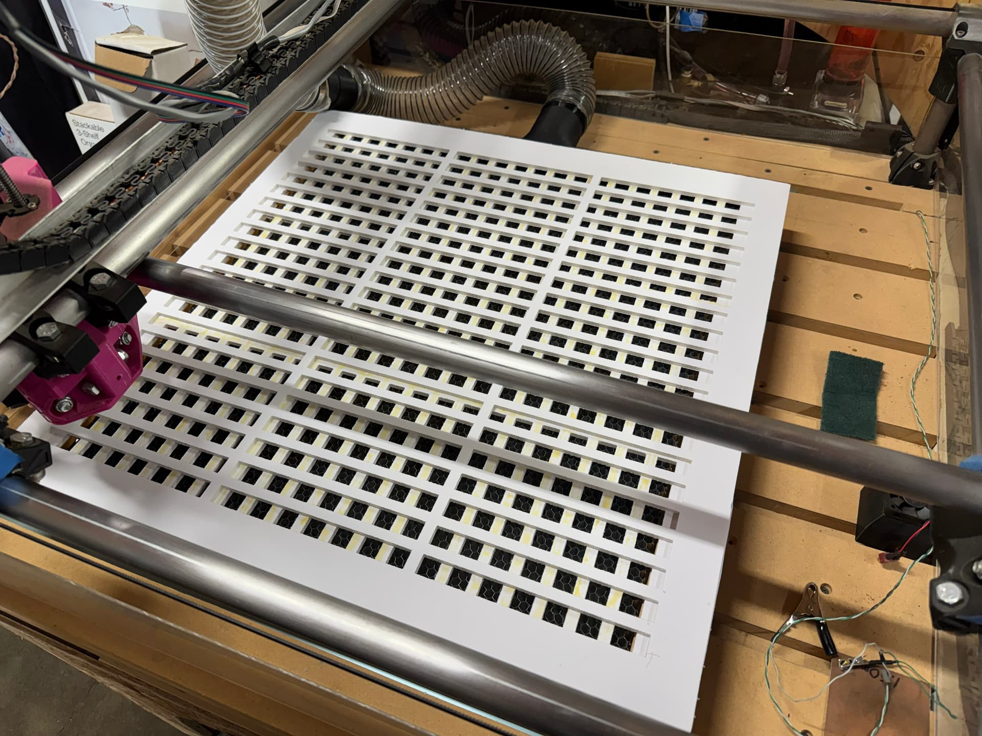
OK so looks like using a rectangular pattern should work well. Here is what I am cutting right now… drawn in fusion and exported/imported as a dxf to lightburn.
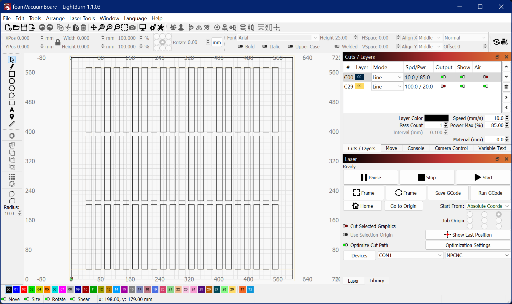
This will sit on top of my 24x24 laser vacuum table, which has a well supported aluminum grid. Now I have fingers crossed my big bouncy house blower that I use for a vacuum drive will have enough pressure to keep a bowed sheet sucked down. It’s a lot quieter than my shopvac, and convenient to use since it’s already integrated with the machine (mounted up with permanent hoses etc).
[edit: I also think I will probably have to make 2 of those grid plates, since the top one is probably going to get weak on one side from the cutting where it will be hard to keep it from falling apart long term. A glued on second layer should do good to provide support I think.]
While I was waiting for that first layer to finish cutting, I drummed up an idea for a heatsink. I took some scrap 0.6mm copper I had from another project, made some fins, and soldered them to the tip. It’s not the prettiest, but definitely functional. After cutting the above grid without the heatsink, the tip felt like it was around 180F based on touching it with my finger. The heatsinked tip measured 104F with an IR pyrometer near the middle of cutting the grid (temp was stabilized already). Not sure how necessary this is, but I guess it makes me feel better knowing there is less heat to cause problems.
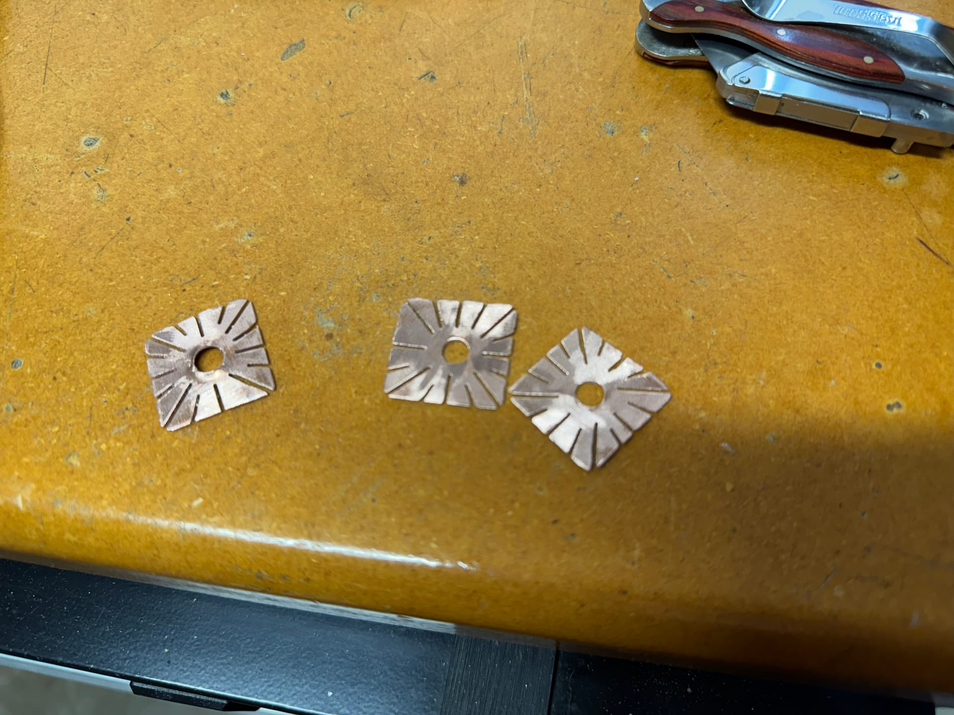
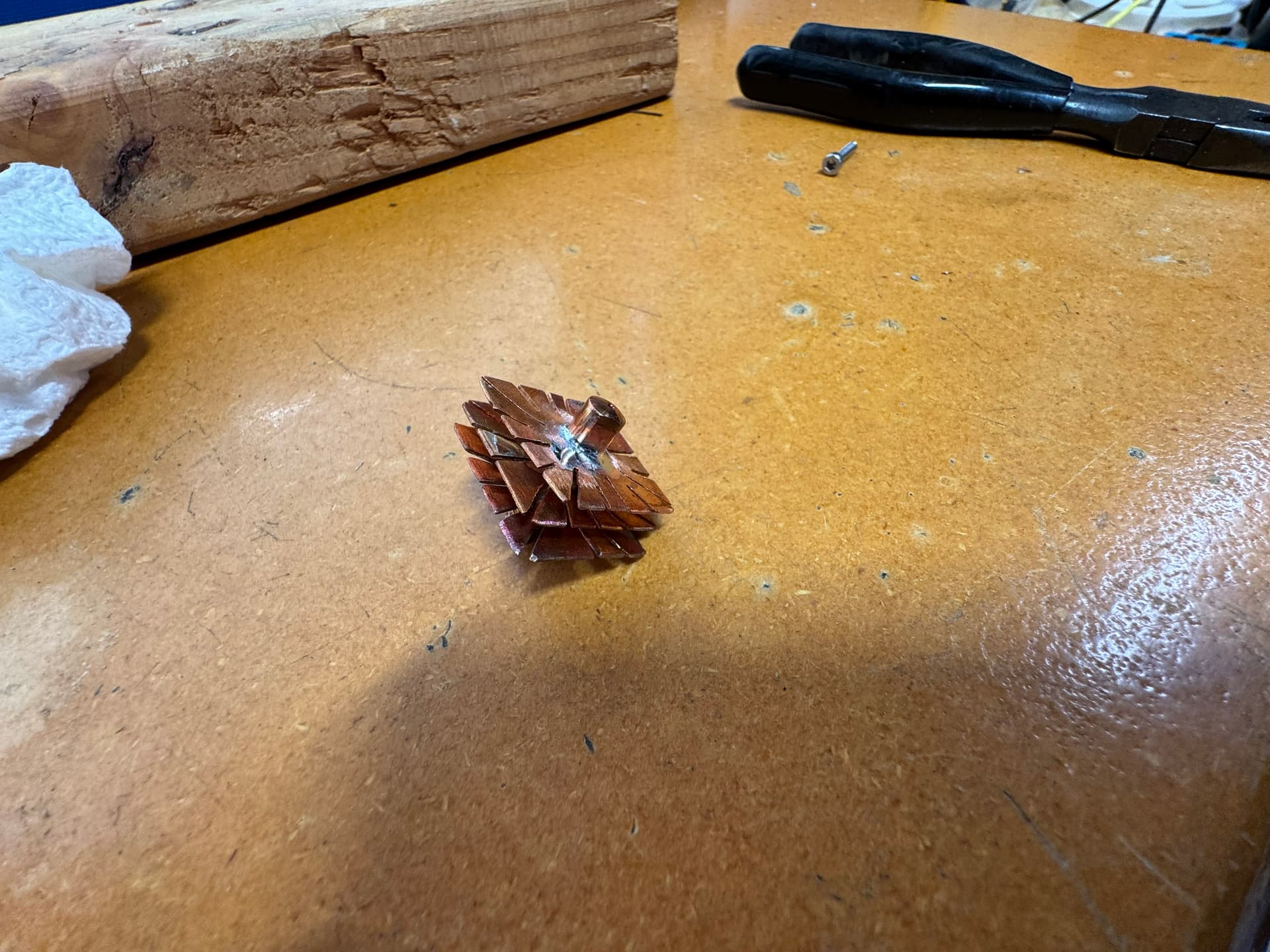
I had to use my plumbing torch to get enough heat of course. I doubt a normal soldering iron would do it, especially after one or 2 fins are soldered on. To get a tight fit on the tip, I under drilled the holes and used a tapered punch to swage them out. Then before soldering I tapped gently on the protruding lip until the fit was just right.
3 Likes
Awesome! Glad to hear it!
If you need access to Custom GCode I’m happy to renew your key for you - send me a DM here with your license key or the email associated with it. This use case is weird. We like weird.
3 Likes
So my vacuum table idea worked very well. The bouncy house blower I have provided plenty of hold down suction on the new foam grid spoilboard thing I added to my laser vacuum box. I kept the design simple and just cut 2 of the same grill patterned sheets, and glued them together with titebond. I used a sheet of foam to provide vacuum clamping force while the glue dried. I ran some test cuts on it without issue. There were some very small peices of foam that would get sucked into the grid here and there. The aluminum honeycomb grille underneath kept those bits from getting sucked into the blower (this was a concern since I didn’t have my vortex filters in place for this). So far those small loose peices haven’t got hung up on the head or caused any issues, but it does make me think using a finer pitched grid on top might be a good idea. I tried keeping the slots as large as possible to maximize the vacuum force; there is an interesting tradeoff between vacuum force available and parts getting sucked in.
On a side note, the heatsinked mig tip I posted about above had issues with breaking needles very quickly. I banged my head on the bench over this for hours, only to discover it was caused by the top fin being soldered on too high, which prevented fully tightening the mig tip onto the wood. While the partially threaded tip was secure enough to work, it remained cocked over at a slight angle. I also thought there could have been added friction due to oxides that may have formed in the tip while soldering with mapp gas. So I desoldered the fins and soldered them on a new tip, using my temp controlled 70W iron set to 330C. There was still some visible oxidization, but mostly the deep orange color, not the blues and yellows created with torch heat. Of course I took care to keep the top fin far from the wood bolts, so it threaded on completely. This new tip is working great, staying nice and cool, and no more broken needles.
I did have a failure of my v-groove bearing after cutting a few kits. The result was a melted flywheel and lost bolt/bearing (I’ll find it someday in a dusty corner of my garage lol). The bearings have no shield or seal, so I’m pretty sure the failure was caused by dust ingress mixing with the factory grease packing. I cleaned the other 7 bearings that came in my amazon order with ultrasound and acetone, then lubed them all with triflow ptfe lube. That should help prolong bearing life by not attracting dust and drying out.
@Colin_LightBurn DM sent. Yeah I’m always finding myself doing things the weird way, aka “wrong way” lol. So far this idea is working better than I thought it would. I think custom gcodes will be the answer to tricking fluidnc into clean cuts with both the laser and needle cutter with minimal fuss.
2 Likes
You’re all set with the most recent LightBurn, you were at least 3 years back on updates, so there are a ton of new features and toys to play with in LightBurn. Even more coming for camera support in 2.1 ![]()
Are you saying it could be possible to run the needle cutter directly from LightBurn, or just generate the G code?
1 Like
In short, yes you can run a needle cutter with LightBurn and custom gcode.
There’s essentially one-to-three missing features from LightBurn that makes this stuff (needle cutters or pen plotters) work well. I’ve overcome them myself with a custom proxy that sits between LightBurn and my controller, but it’d be sooo much better if LightBurn handled it. You can overcome one of them with custom gcode.
The issues are:
-
Lifting the tool between travel moves. This can be overcome by using custom gcode to cause G0 rapids to insert a brief pause, lift the appropriate axis (often Z, but could be A, B, or C), execute the G0 move, and pause briefly (~0.2 seconds) again to let the machine/tool settle before carrying on.
-
Tool offsets. Multiple tools typically require offsets similar to the laser pointer offset already included in LightBurn. If you’re only using a single tool or don’t need to use more than one tool per job this isn’t too big of a deal. You may want to use different machine configs so that you can have your laser pointer offset aligned with each tool, though.
-
Tool selection. Same as #2. If you want to use more than one tool at a time, you need to be able to select them. There’s some clever stuff you can do with a proxy to alter/insert gcode on the fly to make this work using layer speeds as a tool selector, but it’d be awesome (and so much simpler) if LightBurn supported tool selection natively. They already support dual laser heads with Ruita controllers.
I wonder if these are already addressed in the MillMage release candidate.
1 Like
Yep. That’s probably an excellent use case to try in MillMage :Home - MillMage Documentation ← download here
Daryl, have you tried using a ‘z offset’ in lightburn? It is doing the job for me as far as moving the tool up/down between travels and cuts. I usually keep it set to 8mm, and zero the needle so it’s about 2mm above the foam at bottom dead center (for 5-6mm foam). I have lightburn setup with 3 ‘layers’, the first for scoring cuts with z offset going half way into the foam, a second for through holes on the part, and a third for the final profile through cut on each part. I color the layers in lightburn accordingly, so cutting plans in lightburn is a very simple task. I just import the colored file, hit save gcode, send that to my cnc rpi, and hit the green button. With the scoring cuts done on cnc, the FT DTFB planes go together like a dream.
The tool selection and offset thing isn’t something I really deal with for my hobby purposes. Sometimes I might want to laser something after I cut it out with the router, but haven’t had a time where that required any tight tolerances. I do tool changes with the router, but no tool changer so I just rezero z and run a second (or third etc) operation for however many tools. It would be neat to have a tool probe for that, and use tool change gcodes, but I just don’t do enough routing work to warrant getting one and setting it up.
2 Likes
Hey @truglodite, thanks!
I’ve only ever used the z-steps to move the z down for each pass… which doesn’t move z back up during travel moves, sensibly.
Reading the docs:
Z Offset
If you have Z movement enabled, and your controller supports it, you can use the Z offset setting to move the laser head closer to the material (inward) or farther away from it (outward). Positive values move the Z Axis inward, and negative values move it outward.Focusing deeper into the material can sometimes help to cut thicker material, and lifting the laser away from the material can produce a thicker line.
and the tool-tip for z-offset:
Amount to offset the Z into the material (or out of it) at the start of the cutting - useful for deep cutting, or defocusing
…it sounded like it only moved the Z at the start of the cut for the entire layer (given that it is a layer setting). I did not realize (particularly after using z steps extensively before) that it would move it back up for travel moves. Moving back up for travel moves is sensible… the tool-tip could be clearer though. I’ve confirmed that it does move back for travel moves with v1.7.08.
That really just leaves tool-offset and tool-changes for my use, but for regular pen plotter use, yep, LightBurn will do it out of the box.
Thanks again.
1 Like
I was playing with settings in lightburn and managed to produce gcode that did not retract between cuts. The setting that did it is “optimize z moves”. Turning that off gave the proper behavior for needle cutting.
I also noticed the latest version of lightburn always injects s0 and sxxx at every z retraction. This combined with my power on delay arduino, made for very slow cutting. I could not find a way to disable this so I downgraded to 1.78 and the extra sxxx are no longer there. I did have “add s for every g1” disabled in both cases. Not sure if there is a setting in 2.x that allows me to disable the speed calls in between travel/cut.
On a related note, I noticed the FT plans, when simply imported to Inkscape to remove non cut paths, there was a whole lot of unnecessary retract/plunge happening. Sometimes like one cycle every mm lol. My beefed up primo with fast z kept things more sane, but I got sick of it nonetheless. I found the issue is the lines in the plans are all broken up into separate paths, and light burn treats each path as a discrete cut. The solution was in Inkscape, using the join nodes feature to link all the paths for a particular cut. Now each part has 1-3 paths, score, inside cuts, and perimeter cuts, and lightburn does a perfect job with the gcode (only retracting when it has to).
After cutting several kits for myself, I noticed my needle life is very inconsistent. I massaged the guide bearings to give a little more room so the needle never binds between them, and have the tip almost perfectly aligned. The grooved crank bearing rotates in a plane that is aligned with the tip axis too. I tried playing with feed/speed but can’t seem to find the magic sauce for it. Every time it breaks, it’s on the crank bearing, usually on the first 1/4 turn after the counter bend (not at the counter bend usually). So I’m wondering if there’s some bad dynamics going on with the bearing, where maybe the wire gets pushed/pulled too much in that area. I figured having such a large OD groove would reduce stress, but I am stumped on it. Only other possibility is I got a bad batch of wire; it’s k&s brand, from my local hardware store, and doesn’t look rusty or anything.
1 Like