My primo has a working VFD spindle (T0) and a working laser diode (T1). This week I’m working on getting a needle cutter working as well. I’ve read all the guides and have a servo tester, but I figured why not use an arduino to convert from 5khz PWM (common laser power signal) to servo output. This would make swapping between laser and needle transparent… or so I hoped. I made an arduino for this using very simple code, with a 5sec idle output after bootup to ensure the esc always starts up correctly on power up (rc esc’s need to see idle for a few seconds before working). The arduino and needle cutter hardware are working 100% and controllable via gcode (M3, G1S500… etc). The last hurdle for me to get this operational is adding the correct delays after spindle rpm changes and spindle power cycling.
I started off using T1 (setup as a laser tool in fluidnc) for the needle cutter… hoping I can easily swap the laser and needle transparently. I used lightburn constant power mode, along with a z offset to get the correct RPM and z movements. The problem I have is the way fluidnc is handling the G0… it turns off power to the laser, rapid moves, then turns power back on and moves right away… dragging the needle until the esc finish it’s startup and spools up again. I tried adding a ‘G4 P6’ (6sec pause for esc startup) just before the each part gets cut (after Z-height… before the first G1). While this works, it is tedious and error prone.
I was thinking maybe I need to setup a third “PWM spindle” tool on fluidnc (T2), with the proper spoolup delays, but before diving in I figure I could ask here if this would still work as expected with lightburn generated gcode? For this I’d also have to setup a new device in lightburn, but that’s no biggie. Has anyone else setup something similar with success? Any other ideas how to prevent dragging the needle without setting up a new tool? Think my idea should work?
If i were to do it, I’d use the S command for spindle rpm and do it in mill mage, but that might be an uneducated guess. Does the needle need to change frequency much? Well, what i mean to ask: Does it work like a sewing machine with the needle speed changing with feed rate or like a spindle where you set it and just go?
So far I am cutting my exclusively with constant rpm, and doubt I’ll ever change rpm mid operation. The benefit of having it handled in gcode is then I can use my wire for switched 12V spindle to power it, and I can simply hit the green start button and that’s it (vs having to add a pause gcode so I can get the esc spin up before actually cutting).
I am using m3 in lightburn and it is working mostly well, except for it adds an m4 in the header before m3. This makes fluidnc error out, because the spindle is defined without a reverse pin. I simply delete that m4 line and it works as expected.
I did have to add a very long spool up time in fluidnc though… 12seconds to ensure the esc gets booted, sees the idle signal, starts up, and gets up to speed. It’s pretty slick to operate… no needing to pause, play with a servo tester knob, and unpause… just hit the start button an when it’s done cutting it shuts itself off.
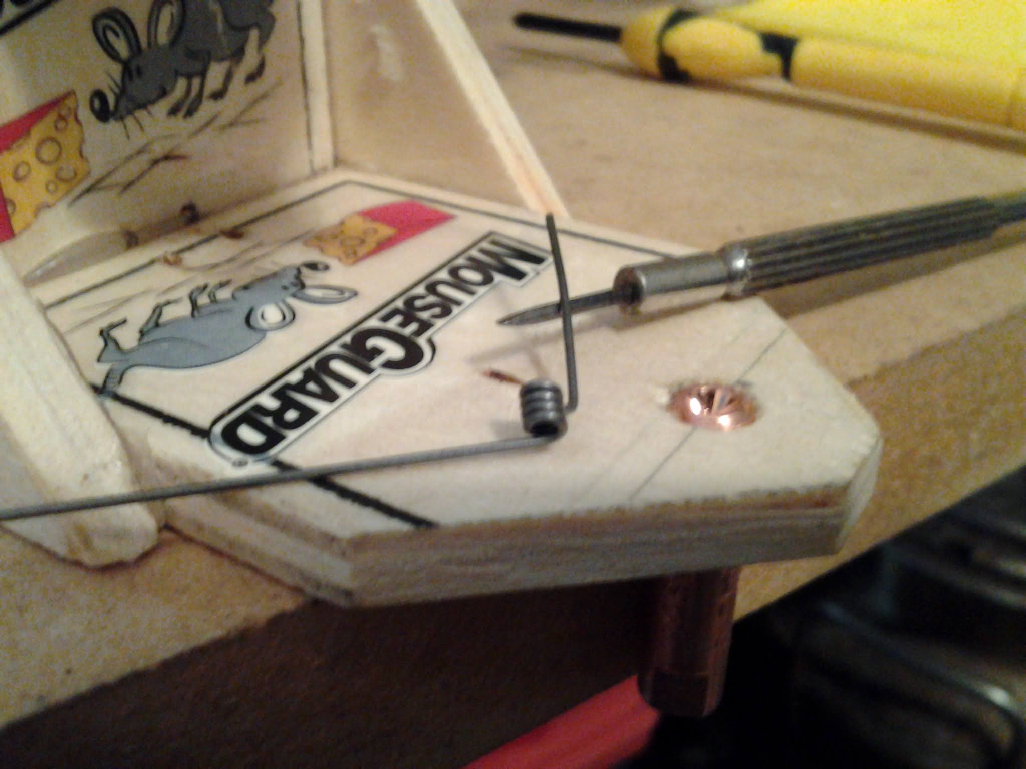
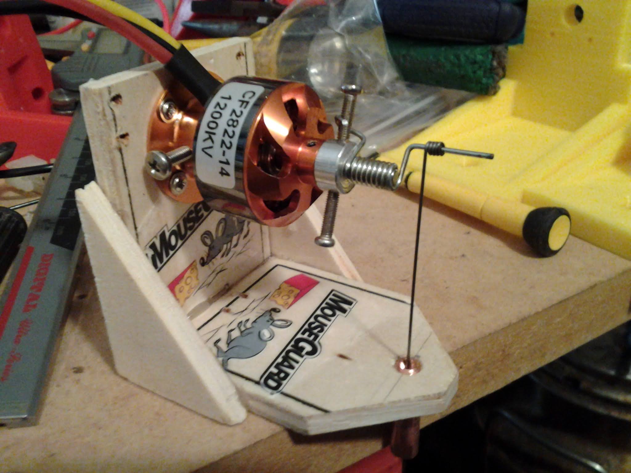
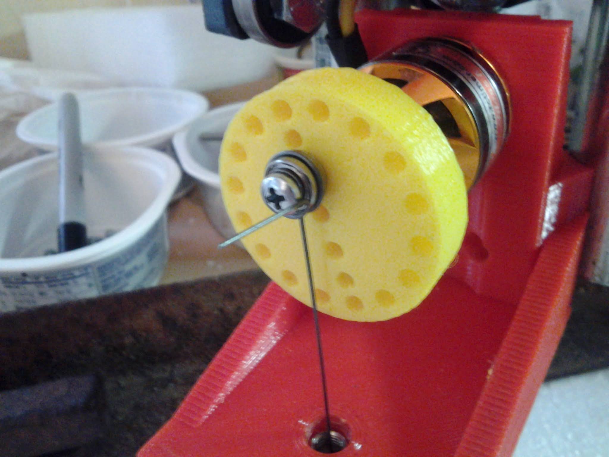
Now I have to figure out why my needle won’t cut more than 12” or so before snapping. I’m using djk4linux’s design, with a modified clothespin spring for a crankshaft, with a copper mig guide and 0.6mm piano wire. I suspect the stroke may be too much; it was hard to bend the spring for less than like a 12mm stroke. Also the design may need more spacing between the first guide bearing and the motor (to reduce fatigue).
where is the needle breaking? Typically it will break at a fatigue point brought on by heat. If the stroke is too long and you are jamming the needle into the wood below the foam and it is bending in a buckle type of situation that could be causing it to snap after repeated motion. Or perhaps it is bending from “stitching” too slow and is actually bending as the core moves and it is stuck in the foam for a fraction of a second and bends. Hard to say, but where it breaks might be a clue. Does it break in the same location each time?
Sometimes it breaks right above the area that stays engaged with the guide bearings, but most often it was happening right at the crankshaft. I oiled it too… and there was heat discoloration on the crank to go with that. I ended up making a shorter crank with around 9mm stroke, and that cut a whole kit in one go without issues (kit consumed 24x24” of blue foam). I also put more care in to how I bent the crank end of the needle; no more slightly kinked wire in the load zone… I wrapped the pliers kink around until it was out of the way. Not sure if it’s the crank that helped the most or the good loop of wire, but fingers crossed I get at least a few more kits before I have to bend/cut another needle for it.
On a related note, I reviewed fluidnc and saw the bldc type spindle. At first I had a palm face moment, then I saw the bldc driver doesn’t offer a spin up delay. So turns out the little arduino pwm to servo converter is the way to go.
Also unfortunately with fluidnc, you cannot use the same pin for 2 different spindles. Makes sense eh? Anyhow, I may eventually run another control wire so I can have the proper 3 tool setup in one fluidnc config file. For now I am working around this by swapping between 2 config files to use the laser and needle.
Kev, I’m afraid that you’ve latched on to something that “came and went”… if I’m reading you right. I’ve never really had an official “design”. If you came up with your design, based on information from the middle of my long-running FT thread… you’re out of date and kinda on your own. That thread simply documents an “out in the open” development of the needle cutter that covers several years of trial and error… and, chronologically-speaking, the most recent – and probably best – information will be toward the end of the thread, rather than in the middle or at the beginning.
The intent of that FT thread was, first (personally), to document progress toward a better needle-cutter than I started with… and, second, to show all the things I (and ultimately others, as they chimed in…) tried, to attain that end. The primary emphasis, above all, was to “use what you’ve got” and KISS. The needle cutter was, and is, DIY… all the way.
Along the way I tried using mouse traps and clothes-pins to illustrate how common everyday items might be used to cut foam. Though not always very practical or long-lasting, I was amazed they sometimes worked as well as they did…
I’m sorry that I wasn’t aware that you were having the troubles you are with needle breakage. But I’m also afraid I don’t personally see it as a big deal to use a servo tester with a simple mark to set in a constant cutter speed… as opposed to setting the speed in gcode. My recommendation is to get away from using the clothespin spring crank… unless you just really want to pursue and develop that on your own. Straight-line motion of the needle in the guide (shown in the video) always seemed the “holy grail” to some folks… unless, like me, you don’t see the spring-steel needle repeatedly bending – well, like a “spring” – as a problem.
It’s late and I hope this makes sense…
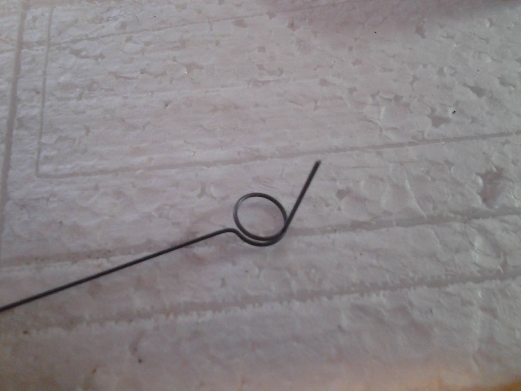
EDIT: BTW stress-risers from using pliers with sharp jaw edges to form the loops in the needle wire will also cause problems… use round-jaw pliers to form loops in the needle. And – never – try to adjust or unbend the wire… once it’s bent.
I haven’t implemented the Jackpot yet, but on my grbl machine I’d just turn off laser mode with a $32=0. To turn it back on is $32=1, so you could include this in whatever start gcode method you use.
12mm stroke sounds a little big but at the same time I’m thinking I probably have around that much stroke on mine…I’d have to dig it out to measure. Though I also usually aimed to have as little stroke as necessary to minimize wear on the needle.
I do agree with @dkj4linux that getting a smooth bend is pretty important - and with the clothespin spring that’s really tricky to do since you have to make such a tight loop in the needle to make it ride on the crankshaft. I tried that setup for a short time and had a number of issues with the needle breaking - and with the crankshaft deforming from the forces on it. I’d definitely recommend looking into one of the flywheel designs. I know a lot of people liked using a 3d printed “carrier” that avoided having to bend a loop into the wire - just a little 90 degree bend to hold it in the carrier - but I had good luck with just wrapping it around a bearing with round jaw pliers - after that I stopped having needle breakage issues.
As for the current issue with gcode control. When I developed mine I was using a RAMPS and just used one of the servo outputs - I’d power the ESC straight off the same 12v that powered the CNC and just left it powered up all the time. Then I’d treat it like a servo and with a little experimentation found the servo setting that gave the RPM I wanted. I gave a few seconds to let the speed stabilize but not much since it would spool up pretty quickly.
My big frustration was that most ESC’s were decidedly not linear by design so finding the right “speed” setting was trial and error. I really wanted to try and ESC designed more for CP helicopters that was designed to hold a stable RPM - but since the ESC’s I was using were designed for traditional multirotors and that’s what the firmware developers were focused on I never found one with a constant speed mode that actually worked. I talked to a few firmware developers and they confirmed it wouldn’t be hard to implement…but none were really interested in doing it. And that code is way beyond my skill level. not that it really mattered since once I found a “Speed” that worked I just stuck with it. Yeah, it would slow down a little when cutting and speed up when free running but it didn’t really matter.
Hopefully in the next few months I’ll be back out in my shop and ready to dust off my needle cutter and see about getting it going on my jackpot now that my LR4 is working reliably. I haven’t really thought about how I’d hook it to a jackpot yet. Still have my laser sitting on the bench waiting for me to get it wired too. Summer just came too early and chased me out of the garage
Thanks for all the feedback everyone! I figured I wasn’t picking up on the latest needle tech. I started off the project picking up on old research when I was looking at making one a while ago. Ironically I did try bending with rounded pliers but they didn’t work that well for the small radius needed on the clothespin. I may redo the design in fusion, using a bearing crank and a longer motor to guide distance. @jhitesma your thing looks like it has a lot more distance than the one I’m using now, which should help reduce bending fatigue. I didn’t really entertain a proper crankshaft and straight needle path, because I figure at these RPM’s that might not last long unless the crank was aluminum or something. I thought the piano wire I was using is spring steel, but alas steel metallurgy is a world in it’s own and there is probably much better available from McMaster or the likes. I have enough extra wire to last a while, but if I ever need to buy more I’ll look into that.
My chase to get gcode working was for 2 reasons. 1) playing with arduino is fun (and I have tons of spare duino boards for things like this), and 2) I didn’t want to have to run more wires for it. Right now the 12V that is on the gantry comes from a spindle relay, which is there for safety when using a laser. It was far easier for me to code/solder that pro mini to the esc than it would have been to run another always on 12V and another signal. Of course, this gives a bit more safety again since there is no servo tester to bump in to accidentally as I’m taping down foam. The whole thing was pretty easy to do. If anyone here is interested in doing it I’d be happy to share any needed details to get you going. The only downside is having to delete that stupid M4 that lightburn adds. I’m using a pretty old version though… maybe that’s fixed in the current version.
You could probably find a pwm to servo converter online somewhere, but likely an arduino will be easier to find and maybe even cheaper. Here is the stupid simple code I am wrote for it:
#include <Arduino.h>
#include <Servo.h>

#define pwmPin 9        // pin that the pwm signal is connected to
#define servoPin 10      // pin that the esc signal wire is connected to

#define pwmMin 0        // micros for off pwm signal
#define pwmMax 200      // micros for 100% on pwm signal
#define servoMin 1000   // micros for esc idle
#define servoMax 2000   // micros for esc WOT

#define escPause 15       // millis to delay each loop (prevent esc errors)
#define startupDelay 5000 // millis to delay non-zero servo signal (allow time for esc startup)

int pwmInput = 0;
int pwmPinState = 0;
int servoOutput = 0;

Servo myservo;

void setup() {
  pinMode(pwmPin, INPUT);
  myservo.attach(servoPin,servoMin,servoMax);

  myservo.writeMicroseconds(servoMin);
  delay(startupDelay);
}

void loop() {
  pwmInput = pulseIn(pwmPin,HIGH,pwmMax);                         // read pwm signal, timing after one period
  pwmPinState = digitalRead(pwmPin);                                // read pwm pin state
  if(pwmInput < 0) pwmInput = 0;                                    // make sure we have no negative dutycycles
  else if(!pwmInput && pwmPinState) pwmInput = pwmMax;              // if pulseIn times out and PWM pin is high, set full throttle
  else if(pwmInput > pwmMax) pwmInput = pwmMax;                     // make sure duty cycle isn't over 100%

  servoOutput =  map(pwmInput, pwmMin, pwmMax, servoMin, servoMax); // map signal from pwm to servo
  myservo.writeMicroseconds(servoOutput);                           // send servo signal

  delay(escPause); // pause to prevent esc errors
}
I did make my “improved” design taller as a few other people had experimented with longer needles to minimize the bending. I figured it doesn’t hurt - but I’m also not completely convinced it really helps that much. I’m pretty sure every needle I broke broke at the bend around the bearing/shaft point - not just along it’s length.
I did like that the longer length and the guide bearings resulted in a bit more “stable” needle at the cutting point. If that makes sense? Basically the bearings guiding it into the MIG tip and the extra length made things run cooler and the needle was more accurate giving a cleaner cut. Shorter needle and no pre-guiding I was initially using a inflation needle (like for a soccer/volley/basketball) and would wear out the sides of them fairly quickly since there was a lot of friction.
The MIG tip is a lot more metal so it’s harder to wear through, and they’re available in different sizes so finding one that matches the needle is easier.
So - while I’m not sure that the extra height and bearing guides are really necessary - I did wind up with a very reliable setup that worked without issue. It probably still works - I just haven’t used it in a few years since I haven’t had time to fly so wasn’t building any planes. I did fire it up a few years ago to cut some sights for my daughters girl scout troop and it still worked just fine.
As for the wire - I just used K&S wire I found at the local hardware store. Didn’t source anything exotic or put any serious thought into the metallurgy other than “Piano wire”
The clothespin crank setup came about in an effort to minimize the mass and imbalance seen in poorly balanced “flywheel” and eccentric setups. Initially, things seemed far better and smoother-running… even without effort to do any balancing at all. They could be made to cut foam quite well for a while… but longevity of the mechanism turned out to be quite poor for most folks.
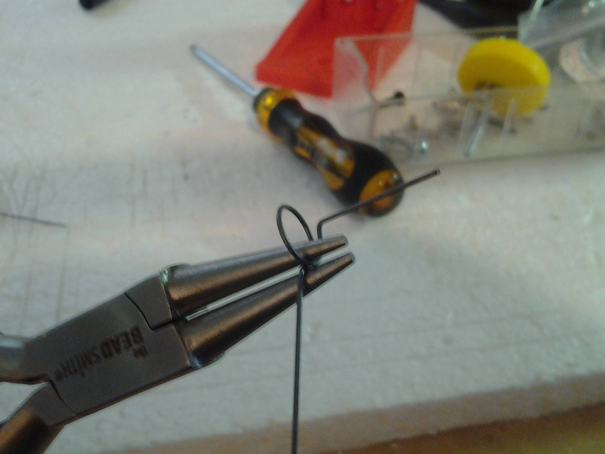
When I was testing the clothespin crank, I would wind several close loops of the needle wire around a small jeweler’s screwdriver blade and then snip off the tail. I really don’t recall ever breaking a needle with this setup during all my testing. The biggest problem I saw with the clothespin crank was that a groove would form where the needle loops wore against crank pin and it would eventually cut the end off… even though I would periodically apply a small drop of machine oil to the needle loops.
I also went by the needle blur to judge whether things seemed kosher or not. I tried to insure the blur was centered and symmetrical and that the entry angle into the guide was as smooth and gradual as possible. This is where a taller cutter body can help. This is also where I judged that pre-guide bearings were not for me… as that would only increase the severity of the bend angle where the needle hit the first guide bearings or pins.
Using a flashlight to illuminate the blur would allow seeing any weirdness or lack of symmetry. I figured cutting forces would only aggravate any non-symmetry and lead to premature failure.
I still like this as a quick and dirty setup. The problem with doing anything to fix the slop at the connection point is that it would only add mass and cause imbalance. Elon’s “the best part is no part at all” comes to mind…
Those are really good photos showing what can actually happen to the wire in motion. I figured it wouldn’t be perfectly symmetrical, and that cutting forces + friction would have some influence on the final path of motion.
It’s interesting to hear you didn’t have issues with breaking needles using the clothespin. I tried several times and even with a minimal stroke it still seemed to break too often. The bend of the needle seemed to have the most influence on longevity, and lithium grease helped a bit. I also see you didn’t use a counter bend on the wire… that could make a big difference removing that stress riser (and since the axle is so small the center is only offset a couple mm at most). Regardless which direction I go long term, I truly do appreciate how the clothes pin idea adheres well to the KISS principle (absolutely love the mouse trap parts too). It’s just that after playing with the clothes pin method for a bit, I can’t seem to make the thing reliable enough for my needs (~30min max needle life for me).
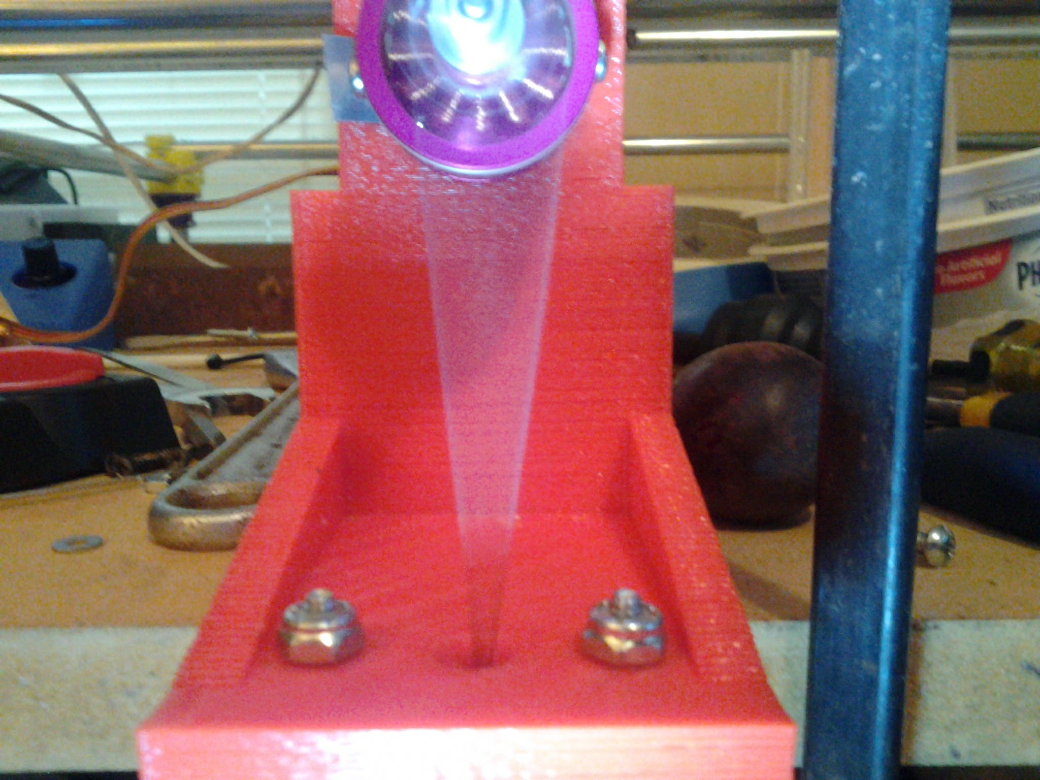
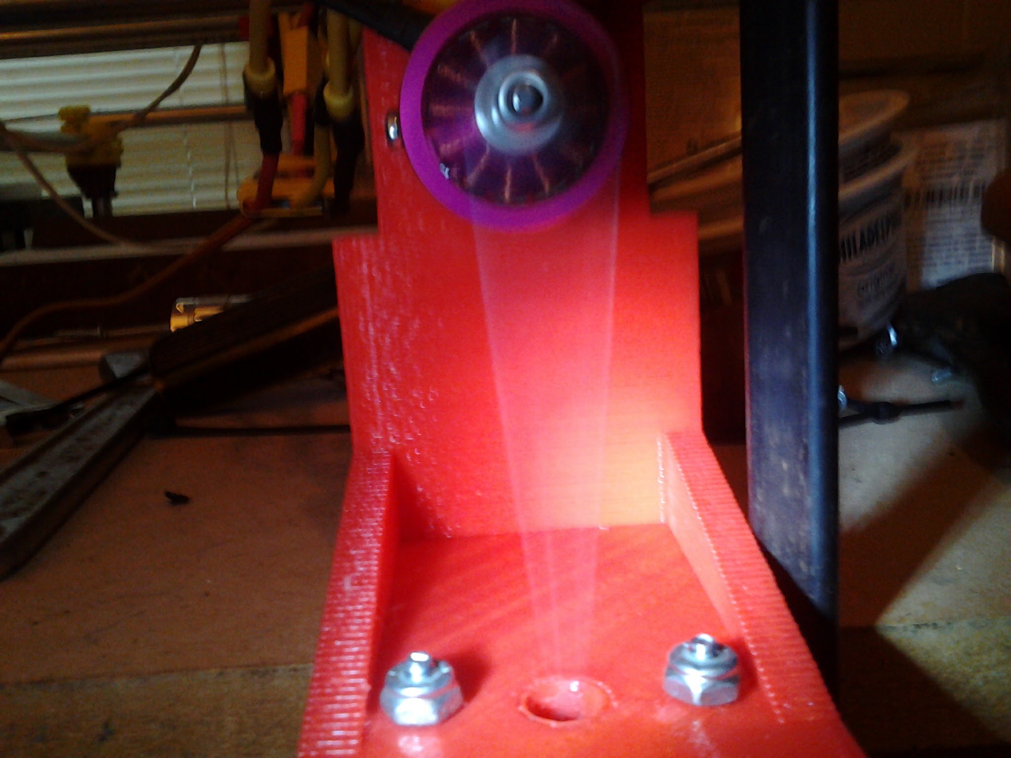
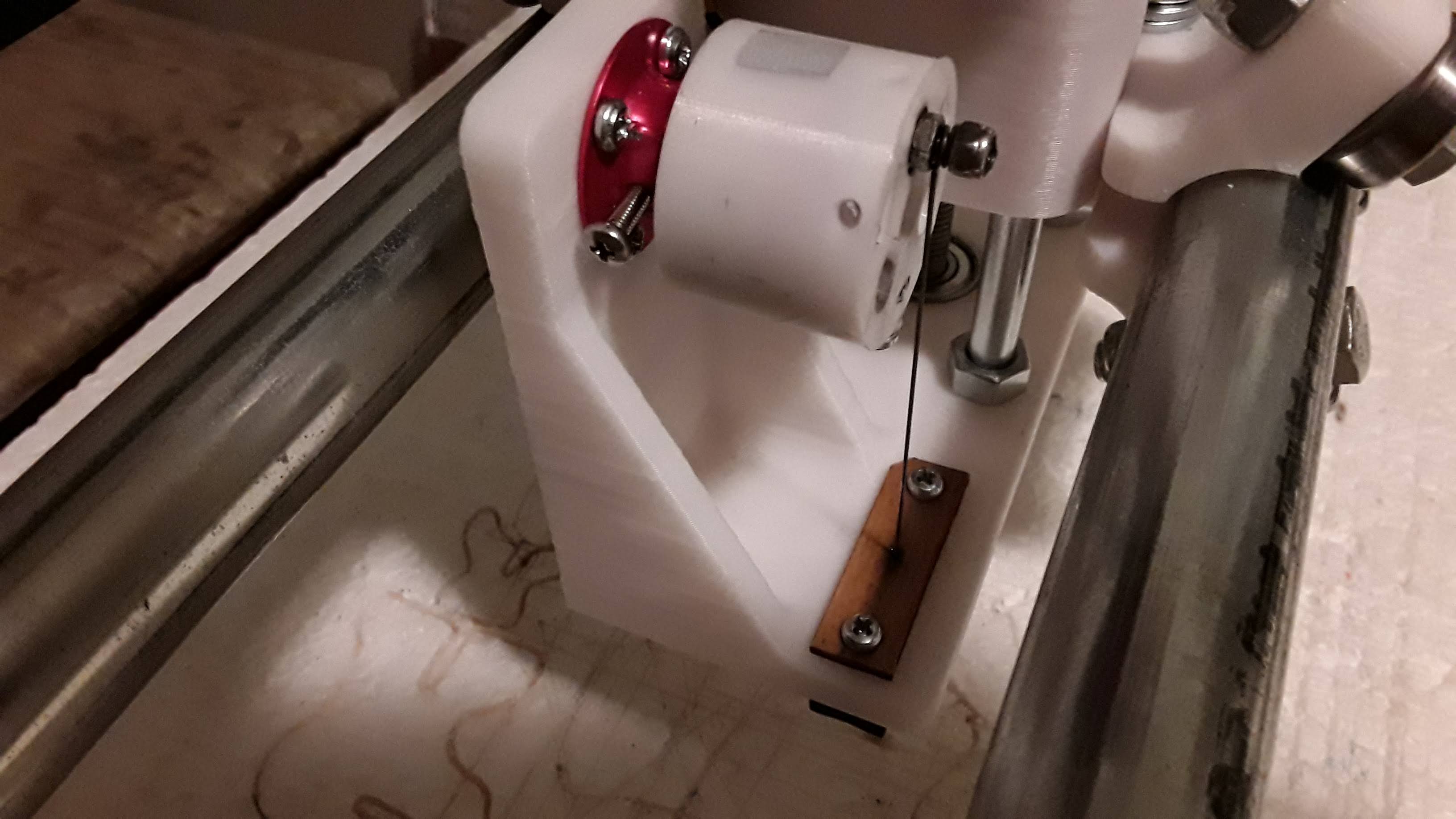
I do like the idea of the guide bearings though. Getting additional motor to first bearing distance is just a matter of drawing the design taller (my printer could do 220mm height if needed, and my latest design with more spacing is just 90mm tall). Having those bearings does help keep the needle in a more constant cutting position, vs having that wagging wire entering the mig tip which results in more of a side to side needle path. I have observed this side-side motion does lead to less perfect cuts… cuts are square when inline with the plane of the flywheel, but tapered on lines that are perpendicular to the flywheel.
I am now printing a full redrawn cutter mount that has 55mm spacing between the motor shaft and the first bearings. This appears close to what Jason did on his, and it is more than double the spacing I had with my original remixed design. Doing the maths, assuming a 14mm stroke, the old design deflected the wire about 30degrees. My new design bends the wire less than 15degrees, and just feeling the wire out with my hands it seems 55mm won’t result in major buckling/asymmetry issues.
My flywheel design is going to be very similar to Jason’s as well… I just went with a 14mm stroke (to make cutting 9mm depron easier), and only has 3 holes; one for a press fit motor shaft, 2 for the wire bearing, and a third counterbored hole for a counterbalance/anti-rotation-pin bolt and bearing. I didn’t go crazy calculating moments of inertia for a perfect balance here, because my crappy motor already shakes a ton without even having a flywheel installed. I’m also relying on a press fit since my motor doesn’t have prop holes in front. If the press fit ends up slipping out, I will probably drill/tap some holes in the aluminum rotor face and use M2 bolts to hold the flywheel on like Jason did.
[edit: I found some 3x10x3 V groove bearings on amazon I’m going to try out on the flywheel. My first attempt using a bearing flywheel I had the wire slip off the bearing every other try. The larger outter race on the V groove bearing will add weight/imbalance, but if that’s an issue I can address that easily. I think having the groove might help make it more reliable. Thoughts?]
My early flywheels used a bearing that I cut a shallow groove in with a Dremel rotary tool and cutting disk. Keeping light finger pressure on the bearing to limit rotation speed, I’d let the bearing slowly spin on a 3mm shaft while holding the disk in the middle of the outer race to cut the groove. You’ll destroy the bearing if you let it free run… ask me how I know.
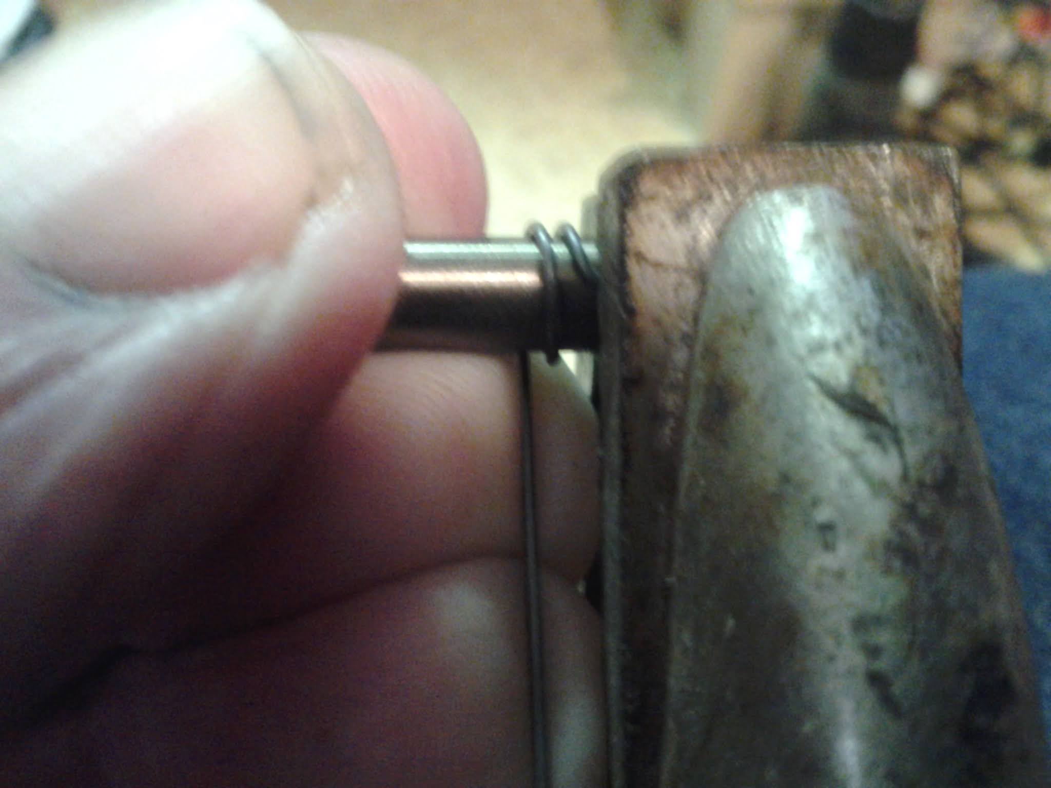
For the needle, I wrapped the 0.025" diameter K&S steel wire around a drill bit shank a bit smaller than the OD of the bearing to form a loop that needed to be slightly sprung open to slip over the bearing OD and then into the groove… and that little bit of spring pressure was actually enough to keep the needle firmly seated in the groove during operation. Also note that I offset the needle shank to “bi-sect the loop” with round-jaw pliers… this insures the symmetry and centered-ness of the needle blur.
IIRC I believe Jason put a drop of super glue on the loop after slipping it in place on the bearing’s outer race… without actually grooving it.
My latest and smoothest-running needle cutter doesn’t use guide bearings… but in a sense I guess it does use an “oily” wooden “pre-guide” above the entry into the main guide. The laser-cut wooden pre-guide had a ~1mm hole IIRC for the needle and along with a stack of wooden plates under the plastic platform for the MIG-tip to thread in to… formed a “sandwich” with the platform in the middle. That left a convenient “cavity” into which I packed cotton and then soaked with 3-in-1 machine oil. This cutter’s dimensions are ~63.5mm from motor shaft center to the wooden “pre-guide” and the eccentric offset on the flywheel of 8.8mm… for a total stroke of about 17.6mm.
I was able to get some of the nicest cuts ever with this needle cutter setup. IIRC I usually set in ~8000 RPM on the cutter speed and 600 to 800 mm/minute feed rate.
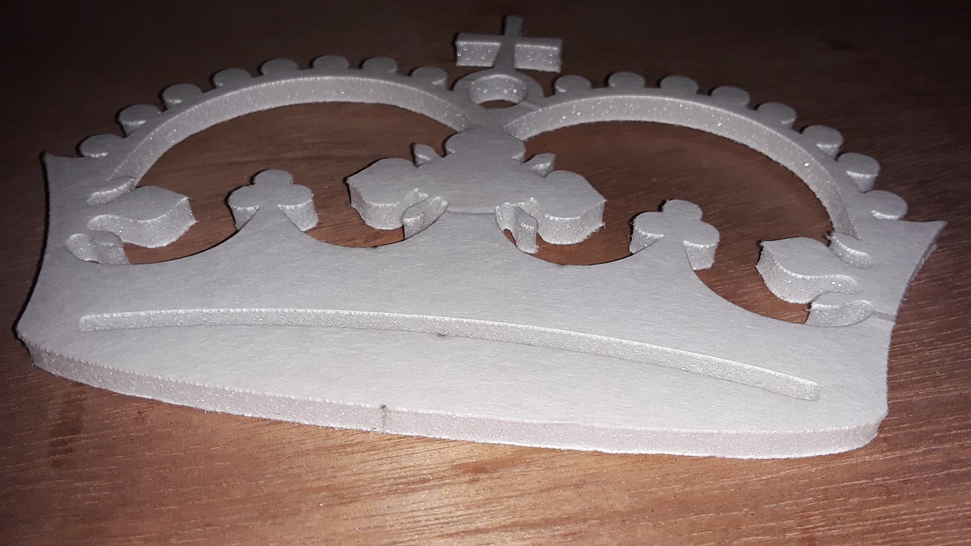
I don’t remember side-to-side motion ever being a problem with the needle cutter… even with some of my earlier cutters. Though there does need to be some slop, I made sure that there wasn’t an excessive amount of “slop” of the needle in guide. I used MIG-tips marked 0.035" and 0.025" K&S steel wire that came in straight 36" lengths. While not all my cuts were “perfect” or even quite as nice as on the crown above… they were always “good enough” for RC plane parts.
Yep, I was going to add that I tried to groove a bearing like @dkj4linux but I had no luck. I tried a couple of different cutting tools but wasn’t able to do much more than dull the outside of the bearing.
I did make the loop in my wire undersized so it had a good bit of pressure holding it onto the bearing - and then VERY carefully added a drop of super glue (avoiding getting it into the bearing itself) on the off chance it may help (I doubt it actually adhered to the outside of the bearing but I figured it couldn’t hurt unless it got into the actual bearing.)
I seem to remember a few people did use V-groove bearings I was just too broke/cheap. a
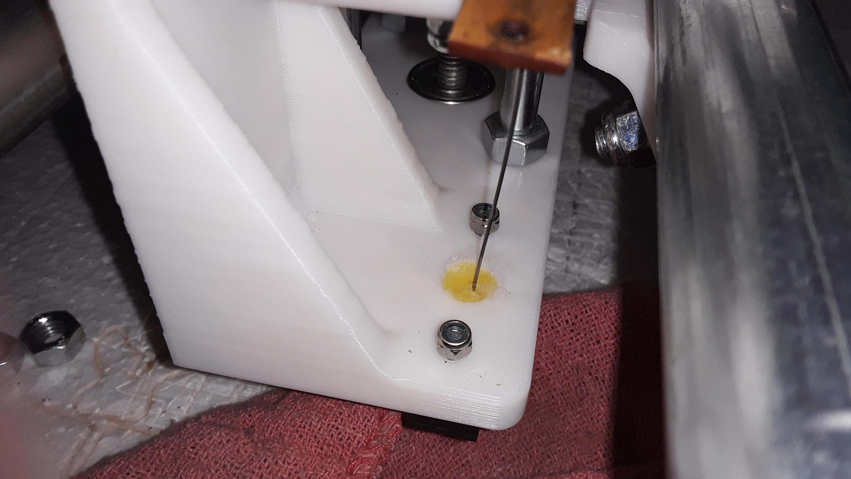
I did use a little oil soaked ball of cotton like @dkj4linux for some lubrication and it did seem to make a difference. Similar setup - I had a piece of wood that the MIG tip threaded into which I then bolted to my 3D print which had a hole about the same as the OD of the MIG tip where I put the cotton.
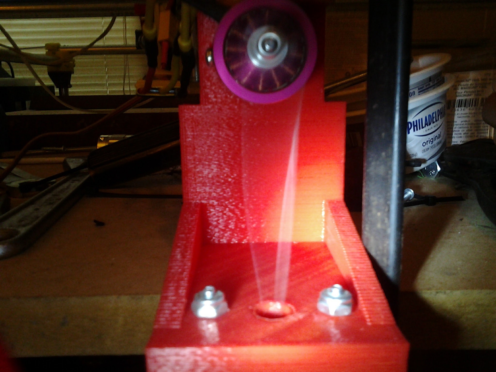
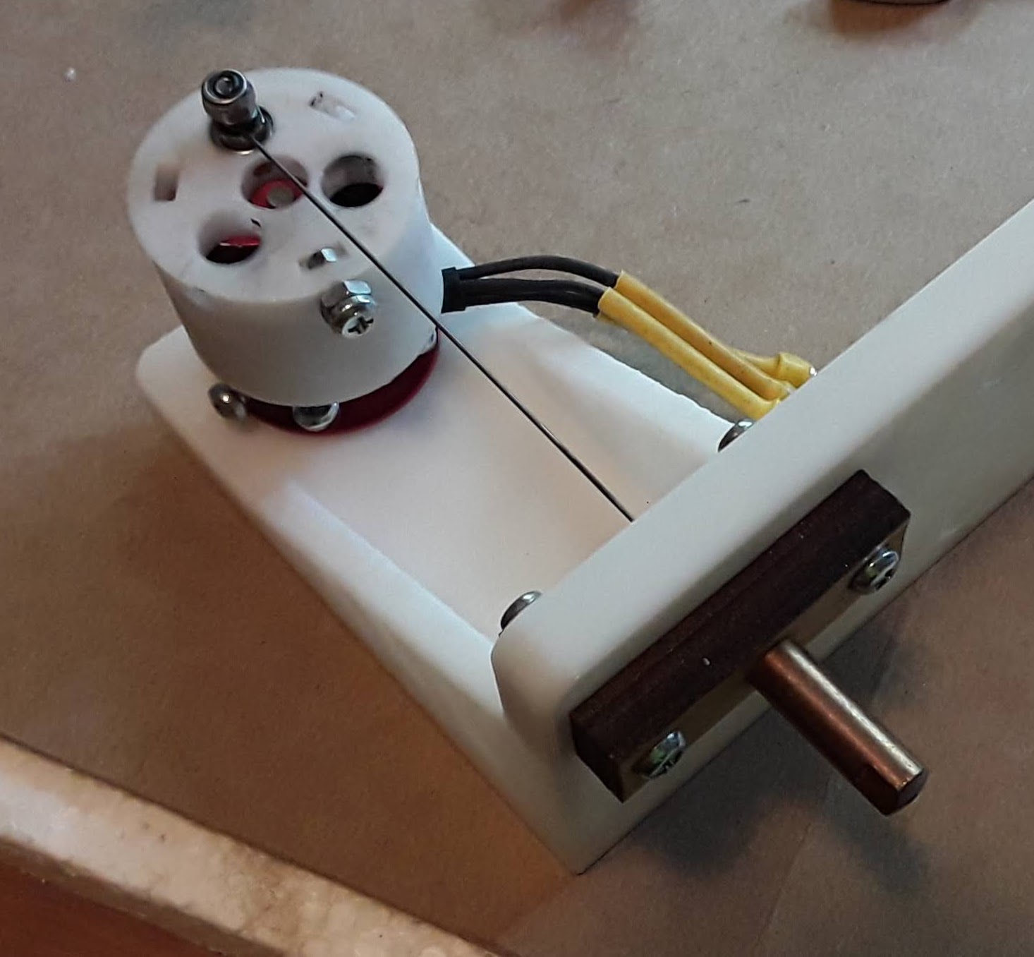
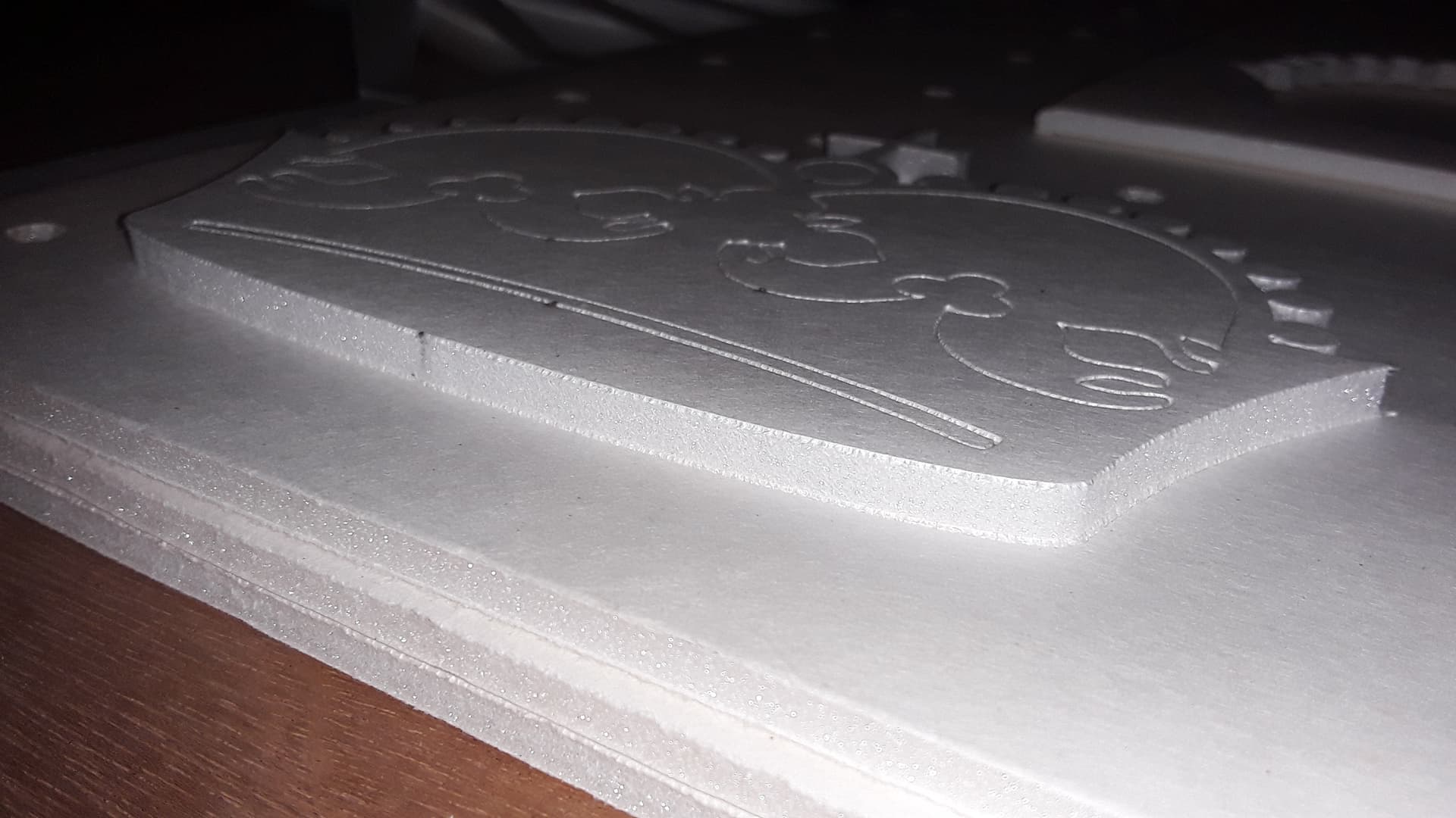
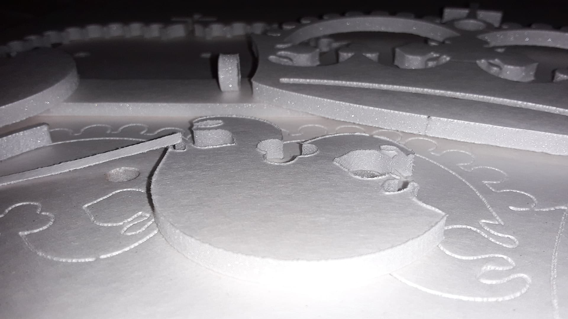
I just wanted to chime in and thank everyone for sharing their journey and experiences with needle cutters. I returned to the drawing board and made a new cutter mount with a lot more crankshaft-guide distance, 2 pairs of carefully positioned guide bearings (0.8mm for 0.6mm wire), a hardwood mig tip mount with oil soaked cotton and a top hardwood ‘tertiary’ guide, and a printed bearing crankshaft. This combo seems like it will work long term.
I started off using a bit too much guide bearing spacing (~1.0mm), which resulted in relatively rough cuts regardless of travel direction. Narrowing that to 0.8mm seems like the ideal number… I observed the same rotational patterns as Jason, and have much cleaner cuts. I also started off with just a 3x6x3mm plain bearing on the crank, but the needle fell off after some cutting on 2 occasions. The second time the wire got hung on the bearing bolt, and created enough heat to melt the flyweel, sending the bearing and bolt flying across my garage, lol! After that I decided the 3x10x3 slotted bearing would be well worth the added weight. I was using a bolt and 2 nuts to counterbalance, and only had enough room on my design to fit 3 nuts. There was still an imbalance, but the whole thing ran relatively smooth and quiet with the slotted bearing, and now the needle seems like it’s never going to break or fall off.
I did note however, that the cuts with this assembly appeared rougher depending on the direction it was cutting. It is hard to tell exactly why; I suspected it could be needle heating is worse in some directions than others, but the foam does not appear melted at all on the rough cuts. There is a definite ‘snagging’ sound when it cuts rough. I figure maybe the problem was my feed may be too high where the needle gets jammed when cutting certain directions. I will experiment further with feed rates to see if it results in better cuts. Has anyone else observed this sort of behavior from their needle cutter WRT feed rate, or is it something else I should be looking at?
The clean cuts though are pretty much perfection… you literally cannot tell the difference between the needle cut and a careful ruler guided cut with a new razor blade… just beautiful what it is capable of. Ironically, my clothes pin rig got the smoothest cuts all around, but I’d be lucky if I didn’t have to use 2-3 needles (with 2-3 more operation cycles) to get a full kit cut. Could my rougher directional cutting now be due to having a 14mm stroke vs the 9mm of my clothes pin (too much needle speed maybe)?
It’s been so long since I setup my laser I totally forgot about laser mode hehe. This would require different startup gcodes to add the delay for motor startup/spooling, but you could use one fluidnc config file. I guess in that sense it’s ‘6 one way, half dozen the other’; change the startup gcode, or change the cnc config (granted, the config file requires loading up the webui etc, and changing the lightburn startup is less clicks to do). Ironically even if I ran another wire and added a 3rd tool to my fluidnc config, I’d still have to edit the startup gcode in lightburn to between “T1” and “T2”. There’s definitely room for improvement when it comes to the FW/software side of this. As is I don’t know of a way to efficiently switch between needle and laser without editing text/files somewhere. I wish lightburn had a ‘tool number’ drop down box or something; still something to edit, but less headache especially if it was easy to change using a toolbar or something.
You could setup a 2nd device in LightBurn, as a custom gcode device, and add whatever gcode you need for the 2nd tool in the custom gcode fields. Then the only thing you have to do to switch tools is change the selected device and re-home.
Would love to see a few photos of your needle cutter. It would go a long way toward helping us see what you’ve now got. Sounds like it has great potential if you’re getting some really clean cuts on occasion.
WRT to the “directional snagging” closely inspect the needle tip. Depending on how you snipped it to length, you might have a “harpoon point” with a barb on one side? I used to use a sharpening stone (with a fish hook groove) to dress the tip… lightly holding the stone against the needle while running and working it all around to remove any barbs.