I have a MPCNC Primo with a miniRambo and LCD from the V1 store. I purchased a Creality 5W laser module that I want to use. I have been reading through the Docs and Forum trying to figure out how to connect it to the miniRambo. Initially I thought it would be pretty simple after reading the Docs. The directions to connect a laser to the miniRambo must be for an older version of Marlin. I tried making the changes and when I went to build it got an error saying that pin 23 isn’t a PWM pin. So I tried changing the pin to 10 and got the same error. I ended up changing it to the FAN pin 8. That allowed me to build my Firmware.
I then read that using the FAN pin may not work because it’s voltage is different than other PWM pins. I’m very confused on which pin to use now.
I also need help with the wiring. I know I need to connect to a 24V power supply. In the forum I read that I need to connect the ground to both the power supply and the miniRambo. I am not sure where to connect to on the miniRambo. Lastly, I don’t know which pin will work for the PWM pin.
Thanks in advance for your help. I’m very thankful for all the knowledge available on this forum!
Assuming you are not using endstops, then take a look at the last couple of posts in the topic that Doug linked.
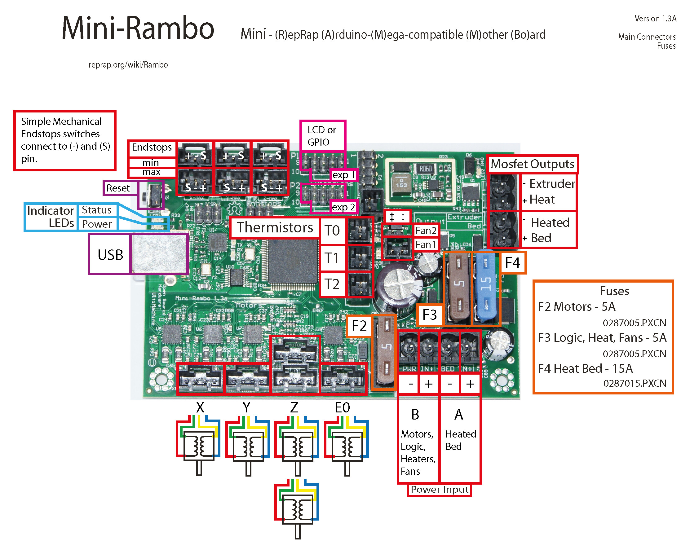
The schematic indicates that X-Min (pin 12), Y-Min (pin 11) and Z-Min (pin 10) are all PWM pins. I’m not sure why you received an error when you compiled using pin 10. Maybe it is because you did not deactivate the Z-Min pin in the pins file. Maybe @Britt can tell us if his use of pin 11 is up and working.
The fan pins don’t work with most lasers, not because they are 12V, but because they are ground-side switching. The PWM is implemented by switching the ground pin on and off instead of 5V. In fact, since the ground side is the thing being switched, you can connect the signal pin on the laser to any 5V pin on the control board to get a 5V signal. If you want to give the fan pins a try, post back and I’ll give you more information.
I need to connect the ground to both the power supply and the miniRambo. I am not sure where to connect to on the miniRambo.
You can connect to any ground on the board. That includes any available ground pin, or even where the ground enters the board. If you use one of the endstop connections for the PWM, I’d use the adjacent ground pin. The amount of current pulled by the PWM signal is very small, so you can use a small wire to make the connection…something like 26AWG or smaller. The ground connection on the laser side varies. Sometimes they provide an independent connection for the PWM ground, sometimes you have to splice into the ground wire supplying power.
@robertbu
Those were my posts ;). I tried changing Y-Min and Z-min to -1 and then setting the Laser pin to 11 and 10. I got the same errors for both.
#define Y_MIN_PIN -1 #define Z_MIN_PIN -1
#define SPINDLE_LASER_PWM_PIN 10 and then 11 // Hardware PWM #define SPINDLE_LASER_ENA_PIN 18 // Pullup! #define SPINDLE_DIR_PIN 19
Here are the errors: #error "Counter/Timer for SPINDLE_LASER_PWM_PIN is used by a system interrupt."", #error “SPINDLE_LASER_PWM_PIN not assigned to a PWM pin.”
Error message:
“resource”: “/Users/me/Desktop/V1CNC_MiniRambo-2.1.1/Marlin/Marlin/src/inc/SanityCheck.h”,
“message”: “#error "SPINDLE_LASER_PWM_PIN not assigned to a PWM pin."”,
It makes sense that pins 10, 11, and 12 cannot be used for PWM if Marlin has repurposed the timer used by these interrupts.
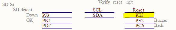
When I look down the schematic, the only PWM pin not accounted for is PE3 which is pin 5. It is listed on the schematic here:
I don’t see where these pins are exposed on the board, and I don’t know if pin 5 is on the same interrupt as 10, 11, and 12.
At one point, just out of curiosity, I researched what could be done with the ground-side switching of the fan pins to generate a 5V PWM signal. I found a few circuits. It might be as simple as connecting a 5V pin to the ground-side PWM fan pin through a 10K resistor. This should produce an inverse, 5V PWM signal, which could be “reversed” using this firmware setting:
#define SPINDLE_LASER_PWM_INVERT false
I don’t have a lot of electronics, so if you want to proceed down this pathway, you will want to run the ideas by some of the forum participants with more electronics experience.
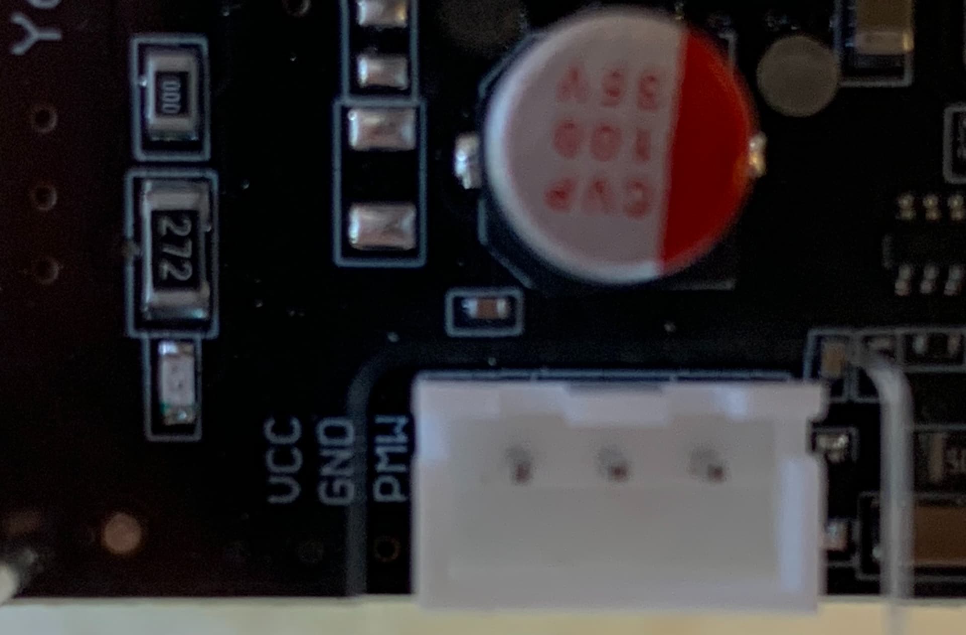
I looked at the same picture you posted, and I could not find that connector(s). I identified all the connectors I can see in that picture. I wondered if it was either 1) under one of the labels in that picture, or 2) on the opposite side of the board, 3) not populated with a connector. It appears to be an interface for an SD card reader.
One thing that puzzled me is that there are two ICSP connectors labeled on the board. I’m not sure why, nor why the schematic does not break them out individually.
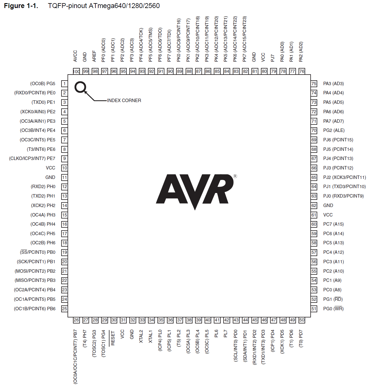
This is a shot in the dark, but it might be worth a try. Here is the layout of the ATMega2560 chip used on that board. Note the index corner for rotation reference, and PH3 as the 5th trace down out of the microprocessor on the left side. You might look on your Mini Rambo to see where that trace goes, plus if you ever have a candidate pin, you can use a multimeter to see if it is connected to that trace:
Thank you again Robert. I will see if I can trace it down. Since I wasn’t getting anywhere with pin 5, I changed the Laser PWM pin back to pin 9 and disconnected my LCD. I was able to get the laser to fire. I was really hoping to avoid using pin 9. It’s a pain having to reflash the minirambo to switch from using the laser to using the LCD. Oh well, at least I know pin 9 will work. Maybe I’ll upgrade to @Ryan 's new board when it’s finished. I really like using the LCD and SD card reader instead of connecting my laptop to the CNC.
There are no “extra” PWM capable pins on MiniRambo for a servo. The Min Endstop pins are PWM capable. If you use min endstops then one of them can be freed up by remapping it to the Max pin.
In “pins.h” under the Mini-Rambo section or “pins_MINIRAMBO.h” (on newer firmware) you will find the pin mapping that need to be modified.
To move X-min to X-max modify the following lines:
Britt tried this above, and it did not work. When he tried to compile he gets this message:
#error "Counter/Timer for SPINDLE_LASER_PWM_PIN is used by a system interrupt."",
PWM pins are driven by a timer. It appears that, after the blurb you referenced in your post was published, Marlin was modified, and the timer necessary for pins 10, 11, and 12 has been repurposed for some other use, making PWM for these pins unavailable.
I’ve seen a couple of circuits that should make the fan pins usable for 5V PWM, but I don’t want to test them on Rambo board and risk releasing the blue smoke.
MiniRambo development - RepRap This is the available PWM pins. You need a 3.3 or 5v pin though. I suppose you could use a heater pwn pin but you would need to supply it with the voltage your laser pwm requires…maybe
Digital pin10 looks to be a good one, you would need to move the probe to Z max though.
It appears that pins 10, 11, and 12, are no longer available for PWM use. See my last post. The sample size is small, but I’ve not seen much success lately using fan pins, even if a 5V pin is used instead of the 12V pin. Historically they seemed to work, but it is possible that the old lasers were taking analog input from the PWM pins.
I tried that and it didn’t work either. Robert told me that they are reserved for some other use. I tried the fan pin and it didn’t work. I was hoping to be able to use pin 5, but nobody can locate it on the board. So I’m stuck with pin 9, which means I have to disconnect my LCD and reflash the firmware. Maybe I’ll be one of the early adopters of your new board so I don’t have the problem of reflashing to switch from the LCD to the laser.
