Hello everyone.
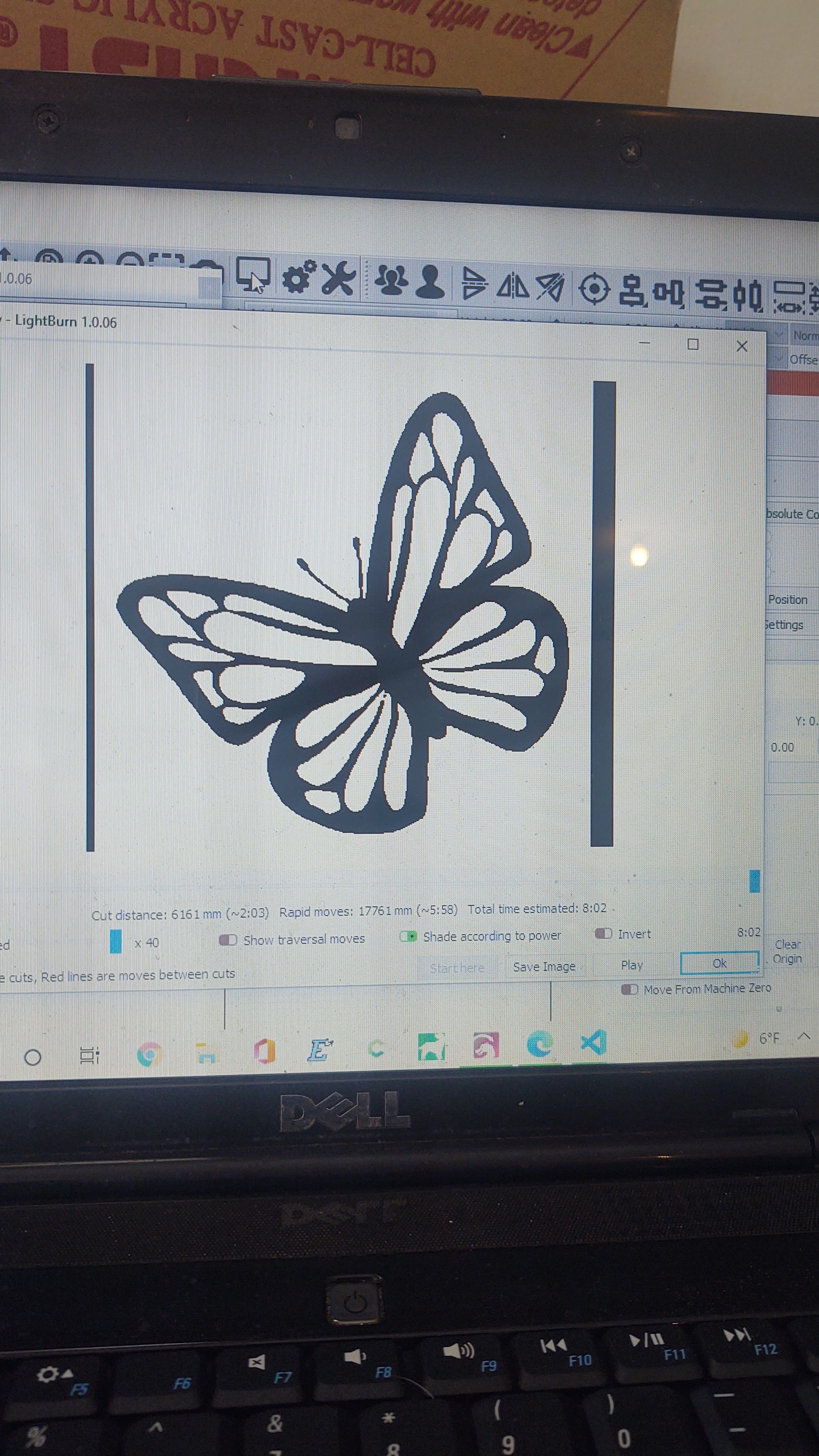
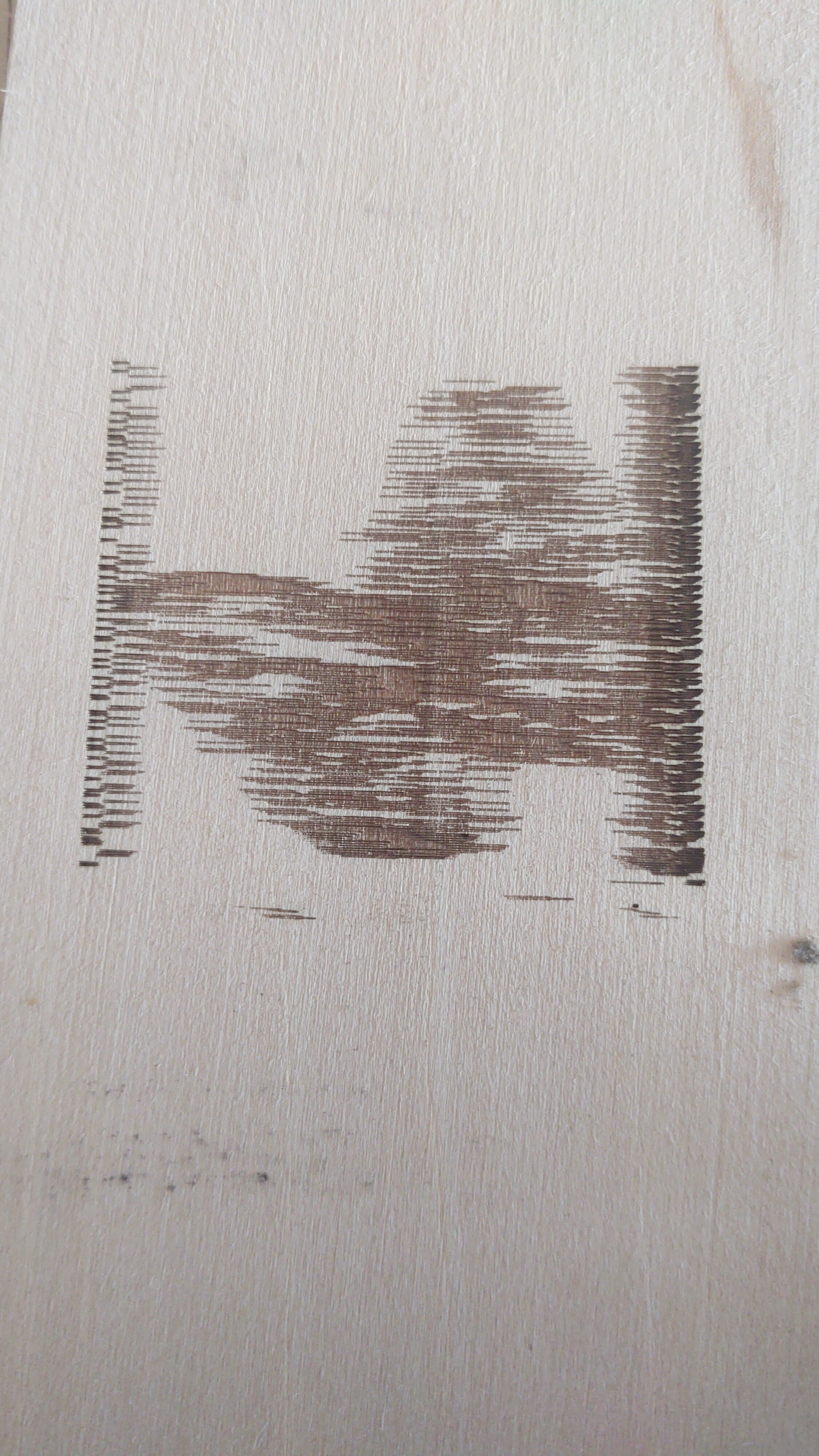
Here are two pictures. The first is what I am sending, the second is engraved.
Lowrider 2, Marlin 2.09.2 on a Rambo mini.
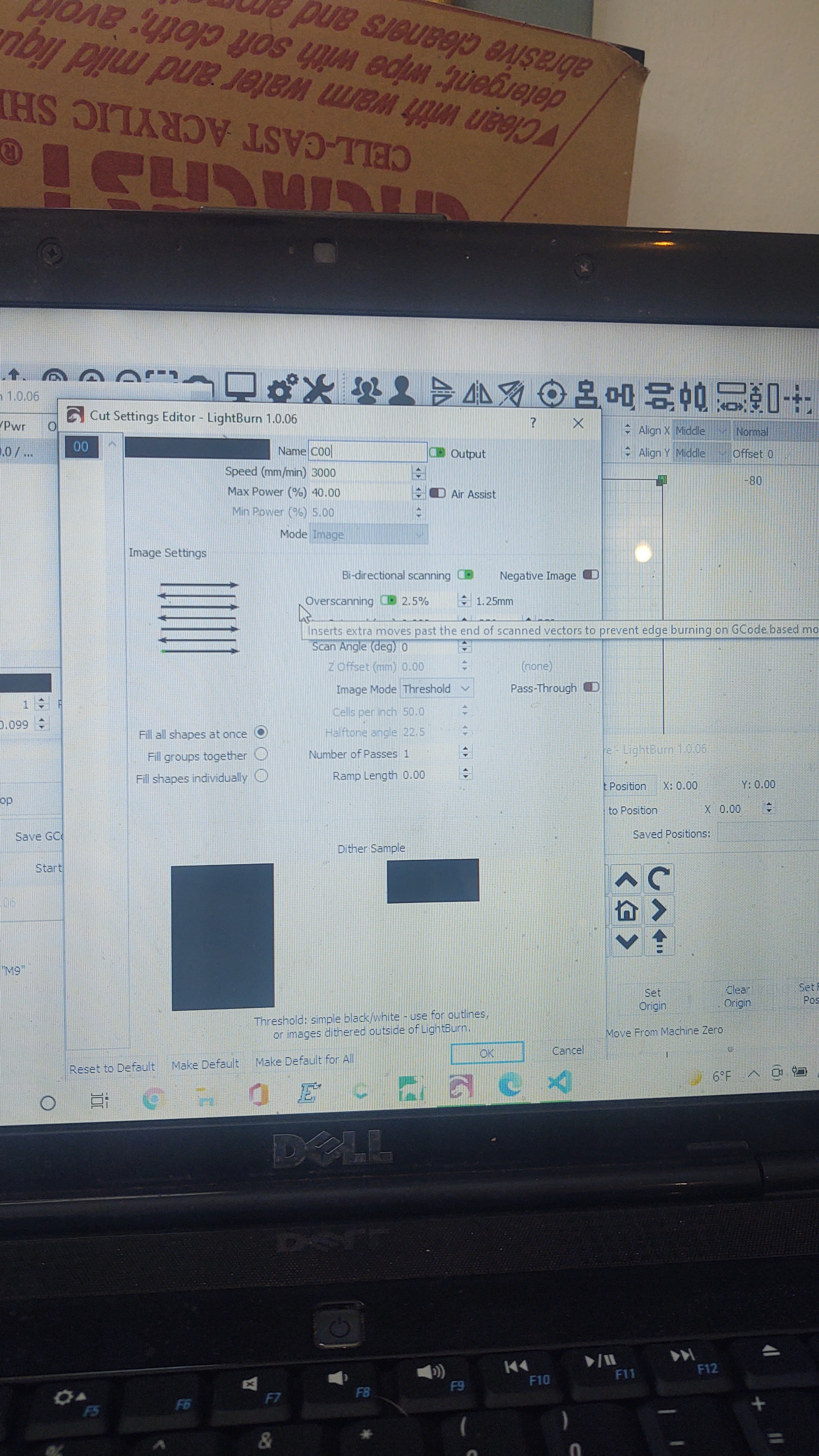
Using Lightburn 1.06 latest download.
No matter speed or power, dithered or threshold.
Laser vector cuts and engraved, no problem.
Laser is 40 w Sovol, 5 watts optical. Using M106/107 on fan 1 pin.
Using Marlin with no edits to configur.h or comfigur_avd.h.
What am I missing here?
I think you need to switch to the spindle_laser stuff and use M3/M4/M5.
Here is what is happening. Marlin has a planner, where it keeps 5-10 commands ahead of where it currently is going. Some commands, like the fan commands, just skip the planner and happen right away. So when Marlin is far behind on moves, your laser turns on. And then it burns the wrong area, and then it turns off a few moves ahead again.
This is maybe the worst I’ve seen it. I think that is because your moves are so long, so 5-10 moves is a very long time.
Older versions of Marlin didn’t have this problem (because all commands were queued equally). Now there are specific laser features and you can set the laser pin. Those M3-5 commands will get queued.
Hi Jeff, thanks for this info
How do I set Marlin up to use the spindle commands?
Is it already setup and I just find the spindle pin on the board?
Will I need a pullup resistor?
Which config files will I need to modify?
What do I change in these files?
Thanks for all the help. I’m feeling a bit
on the dumb side right now, unusual for me.lol
ForbesG
Well, that is a bit out os scope for me. I can’t walk you through it ATM. The settings are in configuration_adv.h. The pin is set in the mini Rambo pins file.
I am not sure, but I don’t think our firmware enables it.
Most likely not. The microcontroller should have an internal pull-up. The one caveat is that it may be floating during startup.
There are few lines in the configruation file(s) that need to be modified. I believe they are all in configuration_adv.h (I’m not where I can check). V1 has enabled the laser commands on the firmware for the two boards they currently sell (and therefore can test): full Rambo and SKR Pro. It is my understanding that all other versions of the firmware V1 maintains do not have the Marlin laser features enabled. The easiest way to figure out want to change is to download the firmware for the full Rambo board and the Mini, and run a ‘diff’ between the configuration.h and configuration_adf.h of both versions. The laser differences should stand out. There are lots of diff tools out on the net, but I’m currently using Meld.
I just took a look at the pins file (pins_MINIRAMBO.h) for your board. The laser/spindle pins are currently defined as:
//
// M3/M4/M5 - Spindle/Laser Control
//
// use P1 connector for spindle pins
#define SPINDLE_LASER_PWM_PIN                  9  // Hardware PWM
#define SPINDLE_LASER_ENA_PIN                 18  // Pullup!
#define SPINDLE_DIR_PIN                       19
Now you may or may not have problems. If you don’t have a display and your laser will accept 5V signals, then you can use the defined pin 9. It is also called PH6, which is the #2 pin in the P1 block on your board
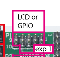
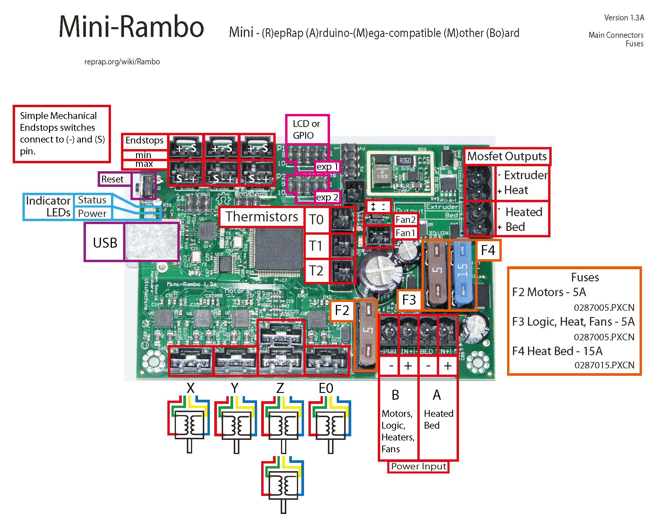
If you take a look at the board layout image here, in this area:
…the laser pin will be the right-most pin just above the “exp 1” label.
Now if you have a display, things get more complicated. If your laser will run fine off the fan pin, you can reassign SPINDLE_LASER_PWM to your fan pin. Some laser drivers, even when they accept 12V PWM, struggle using fan pins because they tend to be implemented with the PWM on the ground pin rather than the hot pin.
And if you get all the above working, be sure to change your settings in LightBurn to “Inline” g-code commands.
Hi Robert,
I can’t find a pins_MINIRAMBO.h file anywhere in the files in the V1CNC_minirambo-2.09.2 folder, what am I missing? If I chose to use pin9, do I need to make any changes anywhere, will the firmware be laser ready at that point and I only need to flash it to my board?
I don’t really need the display if, in the end, my laser works the way I am used to seeing my CO2 laser has worked for over 20 years.
I just need to know what I need to do to get this diode laser working on my Lowrider 2 with the mini rambo or even my ramps board.
Thaks again
Forbes
a I
Hi Jeff,
Found it. Now, if I change the spindle/laser pin from pin 9 to pin 6, the Fan1 pin on the board, so that the M3 M4 M5 will work, or do I need to make the same change in the c*-adv.h or c*.h files also? Then recompile and my laser should work? Or possibly the Z_Min pin 10? Or Z_Max pin pin 23? I’d rather not give up my display for the laser by using pin 6.
The laser does work on the fan1 pin when doing vector files. So, I shouldn’t have to change any wiring at this point?
//
// M3/M4/M5 - Spindle/Laser Control
//
// use P1 connector for spindle pins #define SPINDLE_LASER_PWM_PIN 9 // Hardware PWM Change this to 8 #define SPINDLE_LASER_ENA_PIN 18 // Pullup! #define SPINDLE_DIR_PIN 19
This is getting exciting now, I can see a light at the end of the tunnel.
I’m even feeling am inspiration to get back into the coding I used to do.
Thanks for the help.
As mentioned above, the laser support is not enabled on the Mini Rambo firmware, so just reassigning the pin is not enough. There are just a few lines to be changed, and I believe they are all in c*-adv.h, but you should check both files just to make sure. Using Meld to compare between the full Rambo firmware and the Mini Rambo firmware will identify these lines. Then you just need to use PlatformIO to make a binary.
Ok, getting it. One last, semi-related question. Display wise I have the “fill graphics” display. It no longer displays anything on the progress bar. What’s missing? Can Ii have it display laser info like the fan icon does WRT spindle/laser speed? I can see the fan %speed.
Being a EE I really like a lot of information being displayed.
The Lowrider is really versitile in what it can do and one day I will set it up for a router.
Oh, almost forgot, I want to run two or more lasers in tandem, making the same file. Can the PWM run multiple lasers? With a bed being 800x800 mm, and most of my work in the 100 to 200 mm range, that is a lot of wasted space.
Thanks
Forbes
Love Meld. Very nice. Found the differences and made the change and will recompile tomorrow. No changes in pin numbers until I see that it works with pin 9.
Excited here.
Thanks
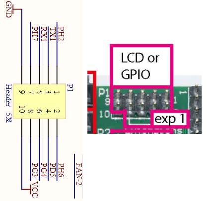
Forbes
As an EE, you are probably in a better place than I am to answer that question. The pins on microprocessor have a 40ma max, so I guess it will depend on the laser control board. My guess is that it will draw a small fraction of this current, but that is only a guess.
I don’t know what a “fill graphics” display is. It would be nice to see more data, but I’ve not read anything on the forum about enhanced display output.
Thanks guys. Got around to running meld on the Rambo and minirambo files and made, what I think were the necessary changes, basically removing the //'s on two lines.
Now, another question:
using PlatformIO, how do I compile to hex and then where do I find that file. I believe the default compile target is .bin.
It’s been years since I used anything like C++ and jsut recently Python on my RPis.
can I define more than one PWM pin for the M3, M4 & M5 commands to run simultaneously?
I like pushing the envelope and working outside the box. And Yes, I am familiar with getting into trouble. Thats why I have multiple machines
Thanks,
Forbes
Last time I checked, there were more than two lines that were different in the section that needed to be changed, but it has been several versions. As for PlatformIO, click that appears automatically whenever one of us uses the name in post, and it will take you to detailed instructions.
Good morning,
OK, I am confused as to which pin to use for the laser M3,M4,M5 commands on the minirambo board.
In the Pins file I have, this is what I see.
// M3/M4/M5 - Spindle/Laser Control
//
// use P1 connector for spindle pins #define SPINDLE_LASER_PWM_PIN 9 // Hardware PWM #define SPINDLE_LASER_ENA_PIN 18 // Pullup! #define SPINDLE_DIR_PIN 19
In a previous reply, I was told it is on the right side of the PH1 connector, I think you meant the left side.
I am also thinking I can assign the Fan pin, which I think is pin 6,or 8 but not the pin 6 or 8 on the PH1 connector, depending on the fan I am using. Probably Fan1 on the board, which is just Fan in the Pins file. How do I do that, as its confusing which pin 6 is going to be used.
Do I use this entire command? #define FAN1_PIN 6 in the above command for M3?
I am a bit confused by the pins at the moment.
Thanks,
Forbes
In a previous reply, I was told it is on the right side of the PH1 connector, I think you meant the left side.
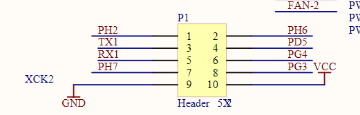
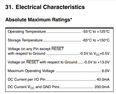
There are a bunch of different numbers that are confusing with figuring out pin 9. There is the Arduino pin number, there is the alternate name for that pin, and then there are connector pin numbers. Let me put the two pictures I posted above in the same orientation:
So, the numbers you see printed on the control board refer to the pin number of this specific connector, not the Arduino number, and you are looking for pin #2 on this connector. PH6 is the pin currently assigned to the laser. It is on the bottom row and right side of this connector as oriented in this picture.
I am also thinking I can assign the Fan pin,
If your laser runs fine on the fan pins, you can reassign the fan pin to the laser control in the pins file.
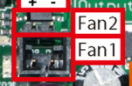
As noted above, some lasers struggle with the ground-side switching of the fan pins. On the Mini Rambo board there are two fan sockets, Fan1 and Fan2:
The matching is a bit confusing. The Fan1 socket on the board is controlled by FAN_PIN in the pins file, and the Fan2 socket is defined by FAN1_PIN in the pins file.
You should be okay just assigning SPINDLE_LASER_PWM_PIN to either 8 or 6 depending on what fan socket you want to use. If pin 9 is free, it would be a good idea to assign the fan pin you are using to 9. That is swap the pin numbers between the current 9 and whatever fan you are using rather than have the fan pin be assigned to both the laser and the fan.
I recently bought a laser cutter and want to use it on my MPCNC. I have been using it with a router.
Is there any reason that I shouldn’t use the Y MIN pin for the PWM to my laser? I am not using endstops, but I do use the Z probe which is pin 23. I have the LCD screen connected to my miniRambo so I don’t want to use pin 9.
You should be able to use any available PWM pin. Assuming the numbering matches the Arduino, then pin 11 is PWM. Even though you don’t use the endstops, you may want to assign Y-Min endstop to a pin other than 11. My concern is that, left alone, the Marlin endstop code might pull the pin high. That would turn your laser on full power.
