I spent the morning working on a prototype for the compass router UI, and I’m really excited about it. I’ve been thinking about how great it would be to have a G-code preview. See it in action here:
I’ve attached my initial prototype and would love to get your thoughts on it. I’m especially curious about these things:
What improvements can I make? Did I get core concepts wrong?
Will this kind of UX be too resource-heavy?
Do you have any tips for making it run more smoothly?
Is there anything I’ve overlooked, or any other features that would be cool to add for a better user experience? (For example, I haven’t included the second drift ring that Cam made .)
Some notes: the direction arc glides way too much in and out of the center in this example, that’s just for the animation. In real life it would only concentrate around the center when you are almost running out of compensation-room.
Looks sweet!! What are you using for the example path? Is it just running pseudo movement?
Looks pretty accurate off the bat. I dig the way it looks. One thing to note is the range is actually a square, not a circle. I think we’d actually have to implement it on the machine to see where it can be made more intuitive.
This is the main things hahah. In the firmware’s current state, this will 100% have to be run on on its own processor. Mayybe if sensing and motor control were put on interrupts it could be possible, but this would cost a lot of relative time in the loop. I bought a GC9A01 module with a built in processor a couple weeks ago with the goal of making a more complex UI, but I haven’t gotten around to it yet. If you’re curious at messing around with it, this is the display I used. They are pretty common on AliExpress because people use this display for smart watches all the time.
Are you using a specific library for the graphics? I’m not a UI expert, but I’ve seen a few examples of cool libraries that help to make nice, smooth graphics. This is one that I stumbled upon that seems pretty common:
Looks pretty good at the moment! Like I said, I think we’d just need to test it out to see what needs to be added or taken away
That was just pseudo movement, yeah. But I actually converted some of your sketch so it works with real gcode movement as well! It simulates the path that we read from the SD.
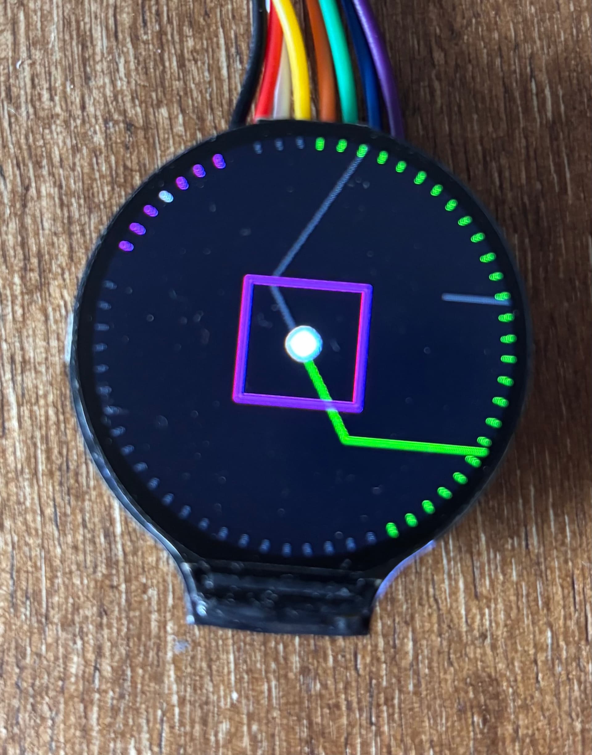
I currently am using the standard Adafruit GFX library. I made some functions so that the display doesn’t fully refresh each time. I also tried my hand at a hybrid approach (see attached photo). The progress and compass indicator are one here, the progress makes room for the compass when needed. That way we only have to keep 60 lines rendered, and we can use lookup tables to prevent calculations each time. The lines are either pink, green, white or grey depending on what they are used for. Maybe that will save on resources. But yeah, only can tell for sure once everything is together and running. Is a fun experiment to get into the groove beforehand .
I tried getting the GPGL ui library working, but man what a pain. I only once got display out over SPI, but it’s buggy and unreliable.the library is made for ESP32’s I think not teensy.
I took a look at your ESP32 display and that could be interesting! Though not much GPIO out in that link of yours.
I have a esp laying around, so it would be fun to see if we could somehow let the teensy stream chunks of past movement, future in progress movement and current direction/speed etc over UART to the ESP32. And have the ESP handle all the UI. That way the teensy could stay in its closed loop and only spit out the chunks that the ESP needs. Gonna try tomorrow and build on the streaming gcode demo that made above image.
As a bonus you could have a web interface as well then. Maybe even upload gcode over wifi or get detailed stats about error rate etc.
So another day another prototype. I soldered some pins to my ESP32-E wroom board that I had laying around. It’s not ideal as it only has 512Kb of ram and virtually no documentation, but after a couple of hours of troubleshooting and rabbit holing I got it working! The display is connected to the GPIO and not soldered on.
next up is try and scaffold a proof of concept UART connection from the teensy to the ESP32.
This is what I got now:
Couple of things:
the rectangle movement is random and way too jittery still. + it’s overflow in its container gets cut off.
I don’t like how the path is intersecting with the progress and compass, going to make a fading backdrop for it.
the rectangle still needs a more ‘danger’ blinkey mode if almost out of the compensation zone
haven’t touched other UI elements. Currently this simple heart takes up ± 30% of ram. But my esp has no other flash which others on AliExpress do. (Got them coming in the mail) that is probably way enough to buffer a lot of paths that we can get from the teensy.
Idea is that the ESP32 keeps a constant connection and updates its UI based on the array of coordinates it gets from the teensy. They can also communicate for example for file lists and communicate back on which file needs to be chosen.
@camchaney is there a loose 5V connection somewhere on the pcb which we can use to power the esp? It takes around 300ma I think.
The ESP needs 3v you probably don’t need 300mA unless you turn on the wifi/bt in which case it can need more
I’m working on a ESP32 (C6) board that replaces the teensy board so we can download gcode over wifi, I have boards but wont touch them until I get my teensy version up and running (almost there) - the big problem with ESPs is not enough pins so you need some external support, still far far cheaper than a teensy
Thank you! I tried it on the teensy’s 3.3 output and it works no problem! That’s handy, so we don’t need a buck converter.
The rudimentary UI currently already takes up 30% of the pram and I see it struggling to get great FPS. (Though the code can probably be a lot more optimized). I feel like the teensy is more expensive but also more powerful in that regard, especially on pram. Are you running into any troubles already?
The rudimentary UI currently already takes up 30% of the pram and I see it struggling to get great FPS. (Though the code can probably be a lot more optimized). I feel like the teensy is more expensive but also more powerful in that regard, especially on pram. Are you running into any troubles already?
A C6 has 512K bytes of sram available, I’m running LVGL on it for other projects with relatively complex UIs - main problem is dealing with unpacking large images which can get really memory intensive
I’m waiting on all of the components to arrive. Right now waiting on my PLA to begin printing the parts. I was hitting roadblocks and fixing logic that mimics gcode parsing and teensy <> ESP32 connection, but quickly figured that it’s better to wait until I have the compass completely build and work with real telemetry instead.
so don’t expect any progress for the coming 3 weeks, but then I’ll gradually post progress here. I bought two ESP32’s to figure out whether a ESP32 + display is the way to go or that we can also make do with a separate ESP and reuse the display from the OG build.
I am fairly certain I can get the UI to work, but looking at older videos of CAM and there are some nuances of the workings of the compass that can only be build into the UI with real feedback.
I could also imagine a solution with an external display.
So a color display, perhaps a slightly larger one, maybe even a touchscreen, which communicates with the Teensy via an extra ESP32.
Then all new GUI updates, etc. could be done in the ESP32, which would then only communicate with the ESP32 via an interface.
This means that the Teensy’s memory and CPU would no longer be burdened.
Could this also be a cool approach for the future?
Touch would also be cool on a larger display.
For now I am focusing on a touchless UI. Having a larger display hinders the UI performance unfortunately. Currently we are working with 240x240 px and that can only get about 20 fps,
Larger screens like 480x480 have 4 times the amount of pixels they need to render. And 480 x 600 6 times. If we throw touch into the mix then there is even less ram and fps available.
So first I am going to optimize for a touch free 240 x 240 display that we will control with the knob. If that code is clean and lean we can certainly look to scale! I also have copyright concerns in the back of my mind if we go bigger and make the UI look like it’s rival ^^’
So, I am really sorry guys… I’ve been working on getting the new ESP32-C3 Mini communicating with my Teensy via UART, but I’ve hit some roadblocks that are eating up too much development time.
I had things working pretty well initially. The ESP32 powers up nicely from the Teensy using pins 0 and 1 with a soldered header, and I actually got full debugging operational at one point where all the Teensy debug and sensor data was displaying on the ESP’s screen through LVGL. The basic UART handshake also functions during setup.
The trouble started after I stashed some buggy code via git and lost the working communication. I haven’t been able to restore it since then, even though I think my new code should be correct. I remember just dumping everything to serial1 originally, but even now changing each Serial to Serial1 didn’t work. To debug the issue, I connected an Arduino Uno to the RX/TX lines to test whether it was a code problem, but the Uno’s 5V logic may have been the final blow to those ports.
Now UART communication only works during initial setup, not in the main loop, and even using Cam’s debug and serial handling functions doesn’t resolve the issue. I’m not sure if this is a code problem or if I actually damaged the hardware.
I’m pausing this ESP32 UI project to focus on solutions that won’t interfere with our existing motor feedback loop using only the teensy. If anyone manages to get reliable RX/TX communication working on pins 0 and 1, I’d be happy to revisit this project!
The ESP32 code for LVGL with the ESP-C3-Mini-U1 and GC9a01 display is available at: https://github.com/darkmattericecoffee/esp32-c3-mini. Also was an adventure to get working, haha! The code should mirror data over RX/TX, but currently isn’t functioning - unclear if it’s software or hardware related.
So that was unexpected, but I am happy to say that we now have full path preview working natively on the teensy.
I experimented a lot with different display clearing techniques, but each technique screwed with the interrupts of the steppers. So I came up with this stippling method which is much easier on the interrupts. I even refactored the menu’s a bit and added a setting Inside the compass UI to toggle it on or off.
Forked the repo so you can take a look a try path preview out for yourself. Would be nice if someone can test it with actuall gcode!
Thank you! And for sure will fix up some bugs coming time. You don’t need anything extra on the parts side. I’ts working on the main chip (teeny 4.1) and its display that is already in the bill of materials. Once we get everything stable and peer tested I’ll do a pull request. I’m sure @camchaney wouldn’t mind merging it into the main firmware branch. Maybe in a ‘experimental’ menu item.
Dude awesome work!!! Looks great! I can’t wait to pull your changes and try it out. I’m really curious to look through your implementation when I get a chance too. I just did a quick skim through the main changes, so apologies if these are dumb questions:
Did you put the stepper motors on interrupts to make this work?
If not, I’m interested to hear more about your “stippling method” for updating the display
Have you had any issues with stepper motors skipping due to the added resource usage?
Hey! Great questions, you’ve hit on the exact problems I was trying to solve with this update.
Sorry for the wall of text in advance ^^.
Did you put the stepper motors on interrupts to make this work?
No, I’m actually not using interrupts for the steppers themselves. From stepper point of view it should be as vanilla as your Repo was
If not, I’m interested to hear more about your “stippling method” for updating the display
The existing codebase already had a clever partial update system where drawUI() was split into passes (using the iter variable) - I just modified it slightly (changed from 6 passes to 5). The key additions I made were:
Path Preview Feature: I added entirely new drawPathPreview() and clearPreviousPathPreview() functions (in new files path_preview.h and path_preview.cpp). Here’s how the stippling works:
Adaptive Point Sampling: Instead of drawing every point in the path, I calculate pointSkip = max(1, path.numPoints / 150) to limit drawing to roughly 150 line segments maximum. For a path with 1000 points, this means I only process every 6th or 7th point, which dramatically reduces draw calls.
Stippled Line Rendering: Between each pair of sampled points, instead of using drawLine(), I calculate the distance and draw individual pixels spaced ~3 pixels apart along that line. For example, a 15-pixel line segment becomes just 5 individual drawPixel() calls.
Still could be smarter Dot Storage: Every pixel I draw gets stored in a PathDot array (max 300 dots). Each dot stores its x, y coordinates and color. This way, clearPreviousPathPreview() can selectively redraw only those specific pixels in black, rather than clearing the entire screen or even a rectangular area. One potential optimization I identified but haven’t implemented yet: the clearing phase currently attempts to clear all stored dots (up to 300), including ones that have drifted off-screen as the router moves. Adding bounds checking during the clear phase to skip off-screen pixels would reduce wasted drawPixel() calls and keep the loop even tighter for the steppers. But I am not sure if they are clipped by te Arduino GFX library regardless, so maybe dynamically managing the array would be wastefuller.
Coordinate Transformation: The path preview uses the same rectangle-based coordinate mapping as the target circle (mapF() with xRange/yRange), so they scale together consistently. The path is also drawn relative to the router’s current position (pathX - pose.x), making it behave like a heads-up display that moves with the machine.
Have you had any issues with stepper motors skipping due to the added resource usage?
Yes, this was a major shitstorm :p. I had line rendering working, but it was audibly pausing the steppers each time the screen cleared. I also experimented by only changing the drawn lines each nth (6th) operation, but that resulted in irresponsive lines. But with the stippling method it still feels like lines. It even looks better on round moves. The steppers remain smooth even with the path preview active. It actually helps a lot when cutting, because now you can anticipate the next move, so I experience it makes it easier to follow complex geometry.
Some other changes: I also refactored the menu logic in encoder.cpp to add preview settings in their own submenu (encoderPreviewSettings()), which lets you toggle the preview on/off or switch between full-screen and rectangle-bounded modes. Interestingly, I didn’t find any performance difference between the two display modes in my tests, so I’ve been keeping it on fullscreen because it looks cooler!
I’ve only tested it with the built-in preset paths. If you get a chance to load a complex G-code file from an SD card, I’d love to know how it performs! Is there any chance you could share the compass logo file you used at OpenSauce so I can test with that? (I haven’t touched Fusion’s CAM yet, but I watched your informative tutorial!)