CNC-cut table for LowRider v3 (parameterized, for cutting full sheets+)

Got more screws (Home Depot had a sale — got 5 pounds of “yellow zinc plated” all-purpose screws for $7 — can’t beat it).

Got the bottom skin completely attached (screws attaching it to not only the X-ribs but also the Y-spars), and the same on top for the MDF top skin. Also attached the MDF spoil board.

I used off-cuts from the OSB bottom skin to serve as backer boards for the metal struts. Glued the OSB backer board onto the X-Ribs, and used screws to hold them in place overnight, and now I’m removing the screws (so they won’t be in the way for the larger screws that will hold on the metal strut. I plan on pre-drilling for the larger screws in such a way that they bite into not only the backer board but also the tips of the X-ribs. I’m currently attaching the first of the metal struts.

Consider just buying Drywall screws

Testing Screws Blog Post

@jtcweb I normally buy dry wall screws, but they weren’t on sale, and they were priced $5 per pound. I got these general purpose for $1.40 per pound.

I buy drywall screws by the 25lb bucket - about $1.70/lb regular price and I’m good for years

1 Like

It’s a good plan. I bought two of the 7lb boxes at $1.40/lb and I’ll be good for years.

This lighter weight design for which the torsion box can be cut from only one sheet of plywood, can serve well on top of a cabinet support structure. If instead you want to use only legs for support, I suggest 6 legs, with two of them in the middle (length wise). Otherwise, the weight of the material added on top can cause the torsion box to bow ever so slightly. (I’m able to check the flatness by use of a laser leveler.) I have my build of this torsion box set on a surface that allows me to shim under the torsion box both to get to a level plane (only so the laser can be used to check for flatness) and to keep the flatness. I have recorded video but I don’t have it edited and posted yet.

Just don’t use drywall screws in wet, or treated wood.

For sure, treated lumber has special coated fasteners

Thanks for sharing @DougJoseph I have used a mix of your and Ryans designs, I liked Ryans due to being metric but preferred your style of braces so have done a bit of a remix.
I do have a question on how you recommend fixing the side rails though(non guide rail side).

In the below image, I was thinking
Red Arrow = 2x Screws per x-brace
Green Arrow = 1x Screw per x-brace
Blue Arrow = 1x Screw per x-brace

The problem with where the blue arrow is that it looks like the centre line/screw heads would get ran over by the rollers, what have you done to get around this or is my calcs off?

That’s a horrible article. His own testing shows why dry wall screws should not be used in structural uses, yet he still concludes that “everything’s fine”.

Drywall screws do not work well in structural uses because they do not bend or stretch or deform. They just flat out snap off. This is especially bad in sheer forces. If a screw bends, it’s still supporting at least some weight. If the head snaps off, that screw is no longer supporting anything, meaning all the other screws are now carrying that screw’s load.

The brittleness also means they don’t do well in situations where there’s a lot of vibrations.

Will anything you build fail because of dry wall screws? Maybe, maybe not. But for the few extra bucks, why not use the appropriate fastener?

1 Like

I haven’t read the entire thread yet, could this table be cut for 1220x610 usuable working area?

@AJG

Hey, glad to see you doing a CNC table! Several thoughts. Re.

I liked Ryans due to being metric …

It’s easy to convert from metric to imperial and back. In fact I can very easily render and provide both metric and imperial.

…but preferred your style of braces so have done a bit of a remix.

My style of braces was patterned after Ryan’s. The two are very, very similar. Essentially the same with only minor differences in which my X ribs are (by default) shorter, so my side supports are shorter. One difference I noticed is that Ryan’s has the top “riding plate” part extended out a bit into the air away from the outer vertical support, while mine was flush with the edge of the vertical support.

My thoughts on assembly / screwing:

  1. You definitely want to avoid screw holes being in the path of the rollers.

  2. You could allow more room to shift the screw holes by shifting the riding plate inward, so less is sticking out, especially if the width has some room to spare. On my design, the riding plates are deliberately “too wide” in both outward and inward directions.

  3. This graphic (that was posted not only here in this thread, but also on my download page on my site) not only tells my design’s default width of riding plates, but also shows essentially where the rollers would ride on them, presuming your tube length matches the tube length specified in the drawing, with some minor variation being possible, allowing for whether your XZ plates are printed (which are thicker) or 1/4" thick metal (which are thinner):

Does this help?

Since the Fusion file is designed to be driven by parameters, it should be doable to edit the params to change the size. The two params in focus here are:

PARAM NAME UNIT EXPRESSION VALUE COMMENTS
Width_Cut_Size_X in 49 49 AKA width of MDF TopSkin. Default 49" which is width of a full sheet of MDF that’s 49" x 97" (one inch wider and longer than 4’ x 8’ full sheet)
Length_Cut_Size_Y in 97 97 AKA length of MDF TopSkin. Default 97" which is length of a full sheet of MDF that’s 49" x 97" (one inch wider and longer than 4’ x 8’ full sheet)

Couple of thoughts:

49" x 97" = 1244.6 x 2463.8 mm

1220 x 610 mm = 48.0315" x 24.0157"

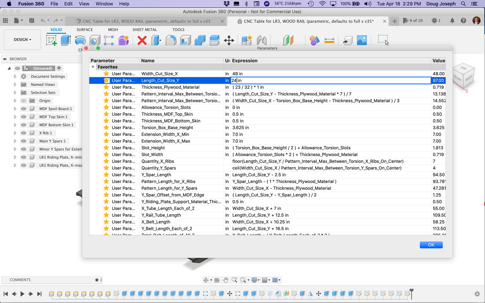
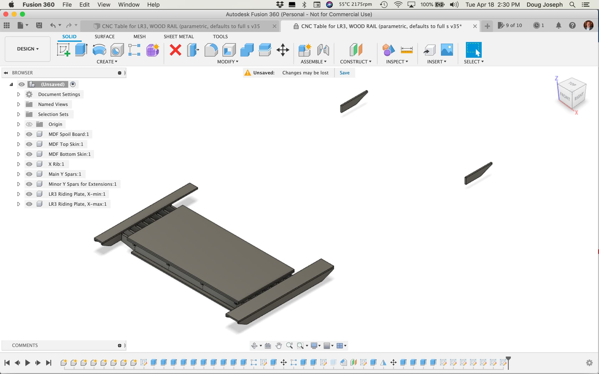
If you change Width_Cut_Size_X to 48", and change Length_Cut_Size_Y to 24"…

…you get this result, which needs at least 4+ steps taken (see below) to be a “whole” design makeover.

Below are the steps, but first …

A. Some of the steps are needed simply because in Fusion 360, the “move” steps in the timeline history seem to not be parameter driven, despite a parameter having been used in the original move. This is disappointing, and I don’t yet know of a fix, so manual additional “moves” are the workaround.

B. For the other steps (not related to moves) this tells me I need to revise how the params interact with each other to get better functionality.

C. A key question here is: do you indeed want the X-gantry on the 48" axis? If not, you would want a variation of this design that has a LowRider v3 on only a 24" wide X-axis, which is doable I suppose. That would require flipping the values in the two params above, and it would alter the fix steps below.

Steps needed to fully implement this design change:

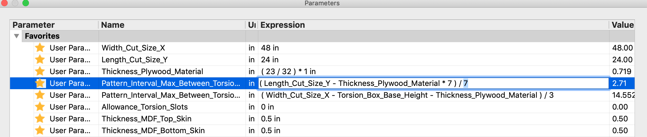
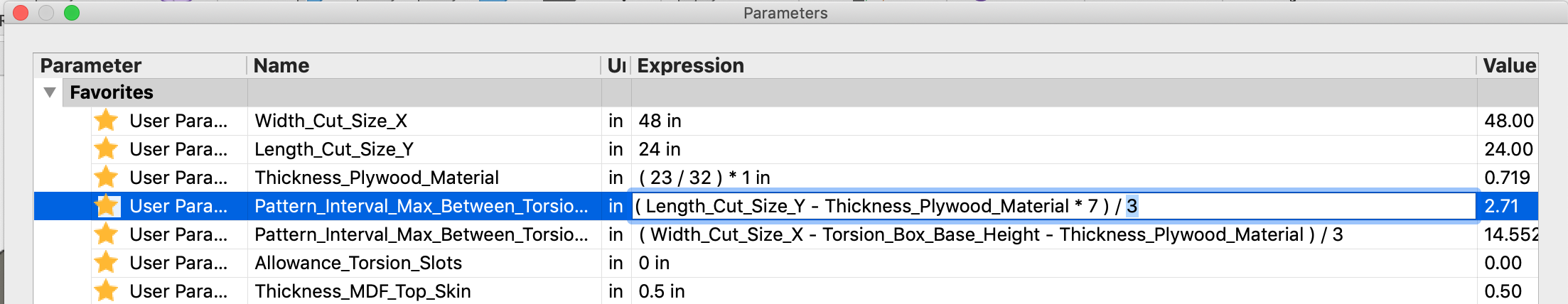
1. Edit the param named “Pattern_Interval_Max_Between_Torsion_X_Ribs_On_Center” to change the “/7” part (which yields 7 X-ribs) to some lower number, perhaps “/3.”

BEFORE:


AFTER:


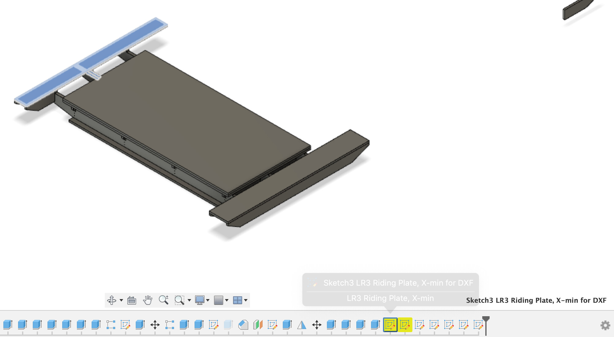
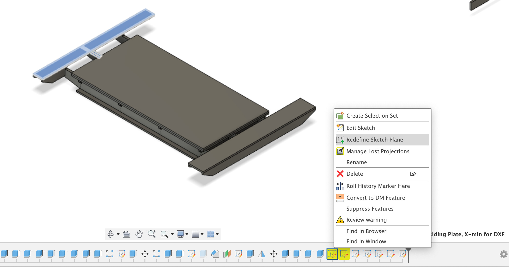
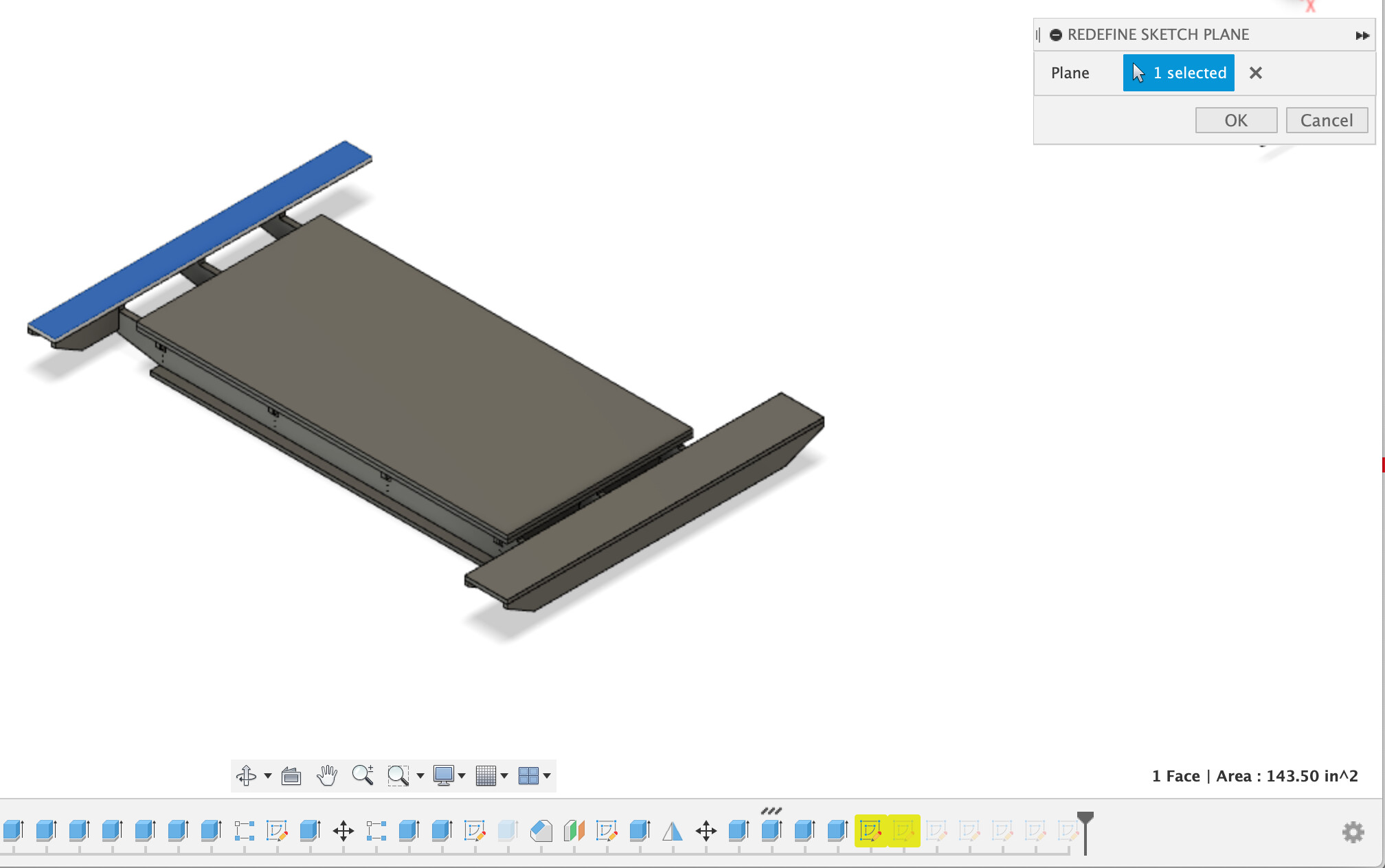
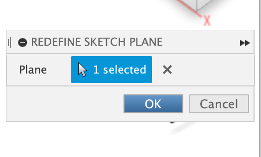
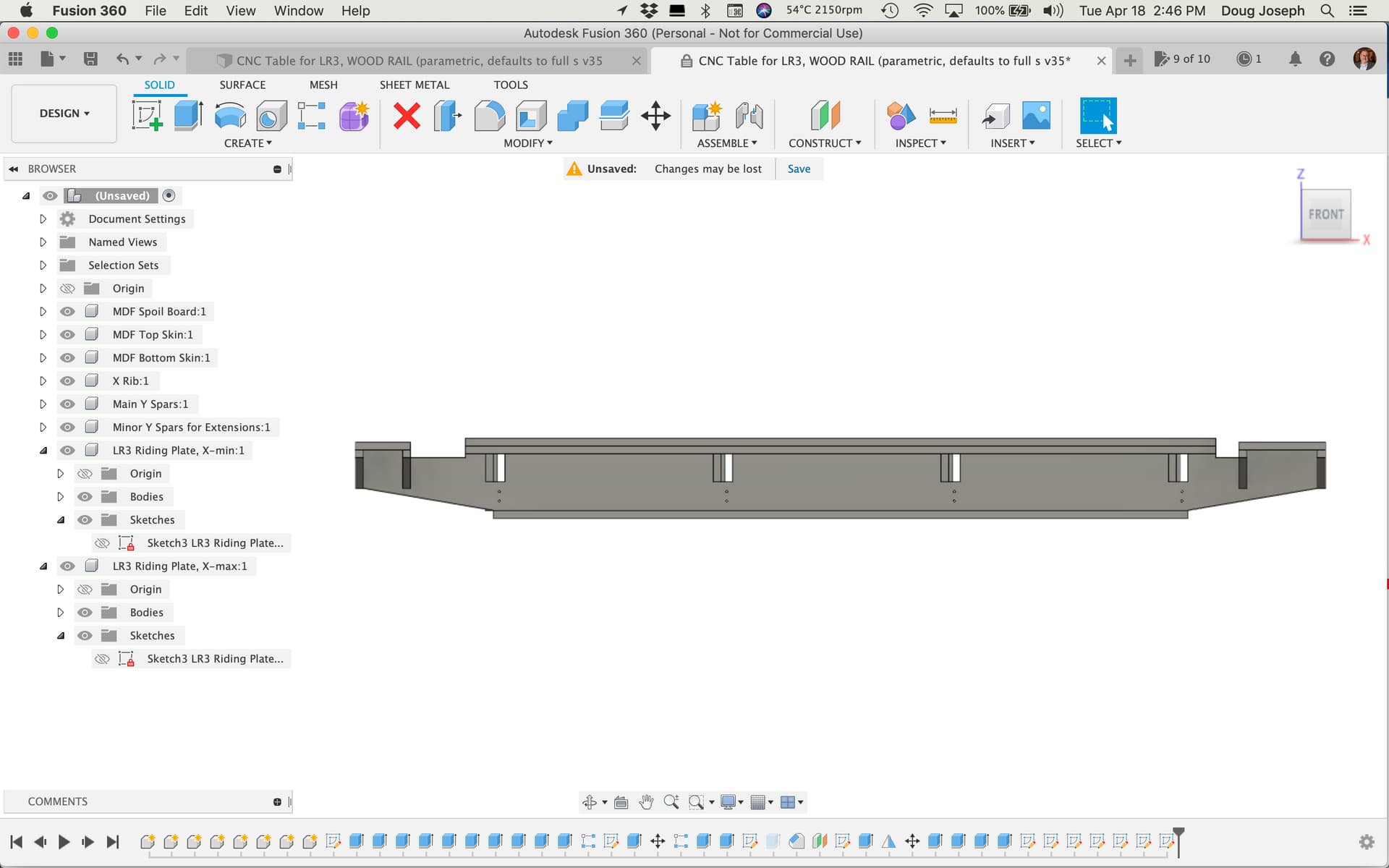
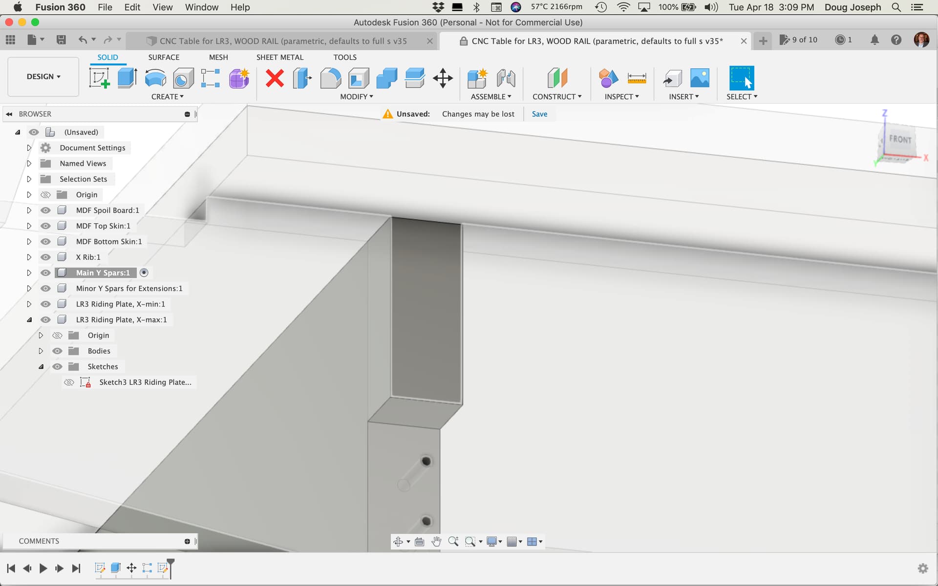
2. two of the sketches made for exporting DXFs, lose their plane of reference. One is “Sketch3 LR3 Riding Plate, X-min for DXF” and the other is “Sketch3 LR3 Riding Plate, X-max for DXF” — there is an easy fix. In the timeline history, you right click on a sketch that’s lost its plane of reference, and choose “Redefine Sketch Plane” — and note that a visual cue for which plane is discernible because clicking on the sketch icon in the timeline history highlights the sketch itself, which is laying on the face of the “body” that is the plane that it needs connected to again. See screen shots for me making this fix for “Sketch3 LR3 Riding Plate, X-min for DXF”:

Screen Shot 2023-04-18 at 2.41.18 PM

… I then repeated for the other side, “Sketch3 LR3 Riding Plate, X-max for DXF.”

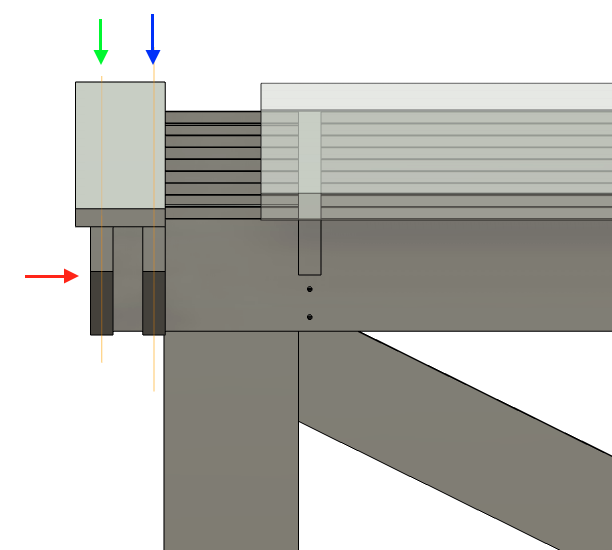
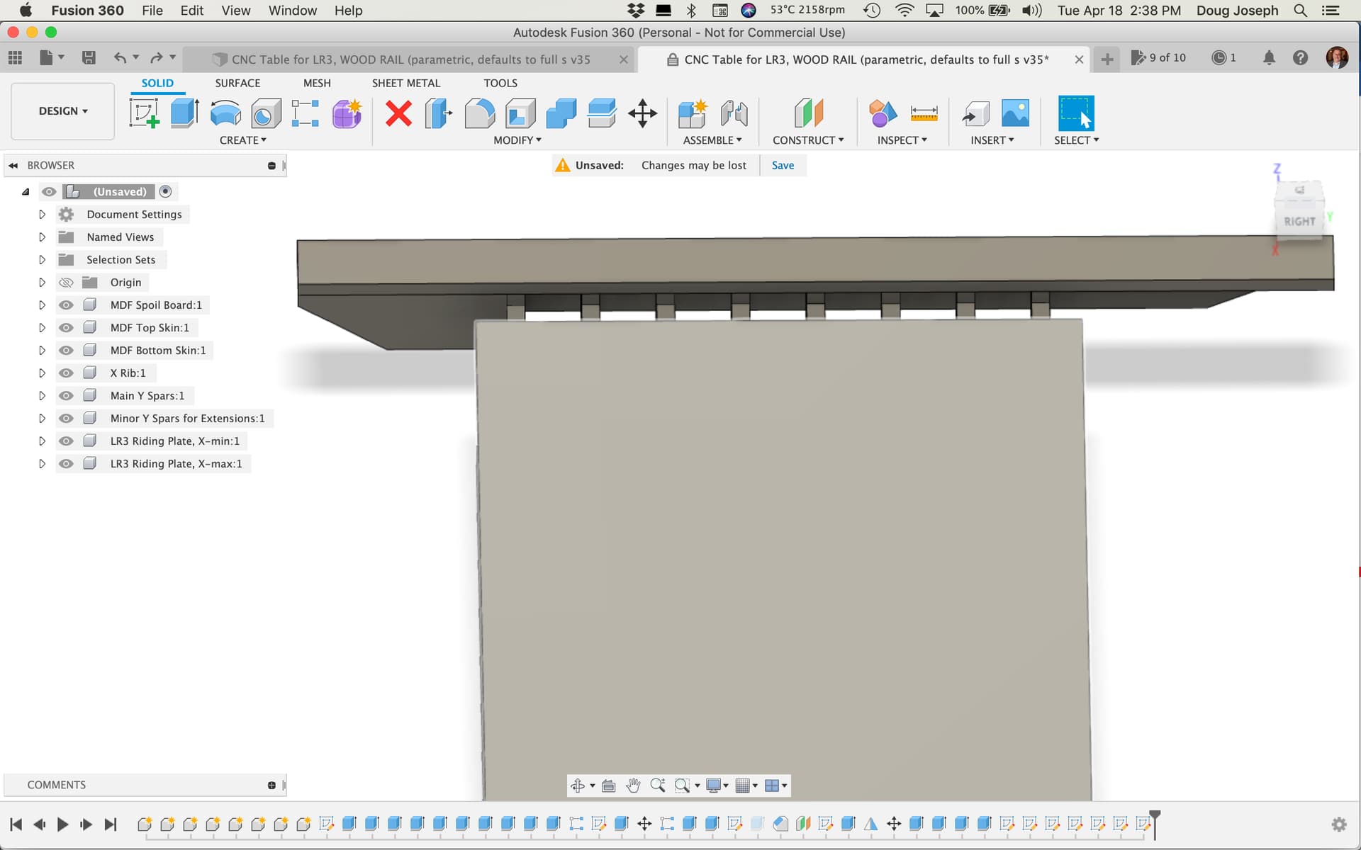
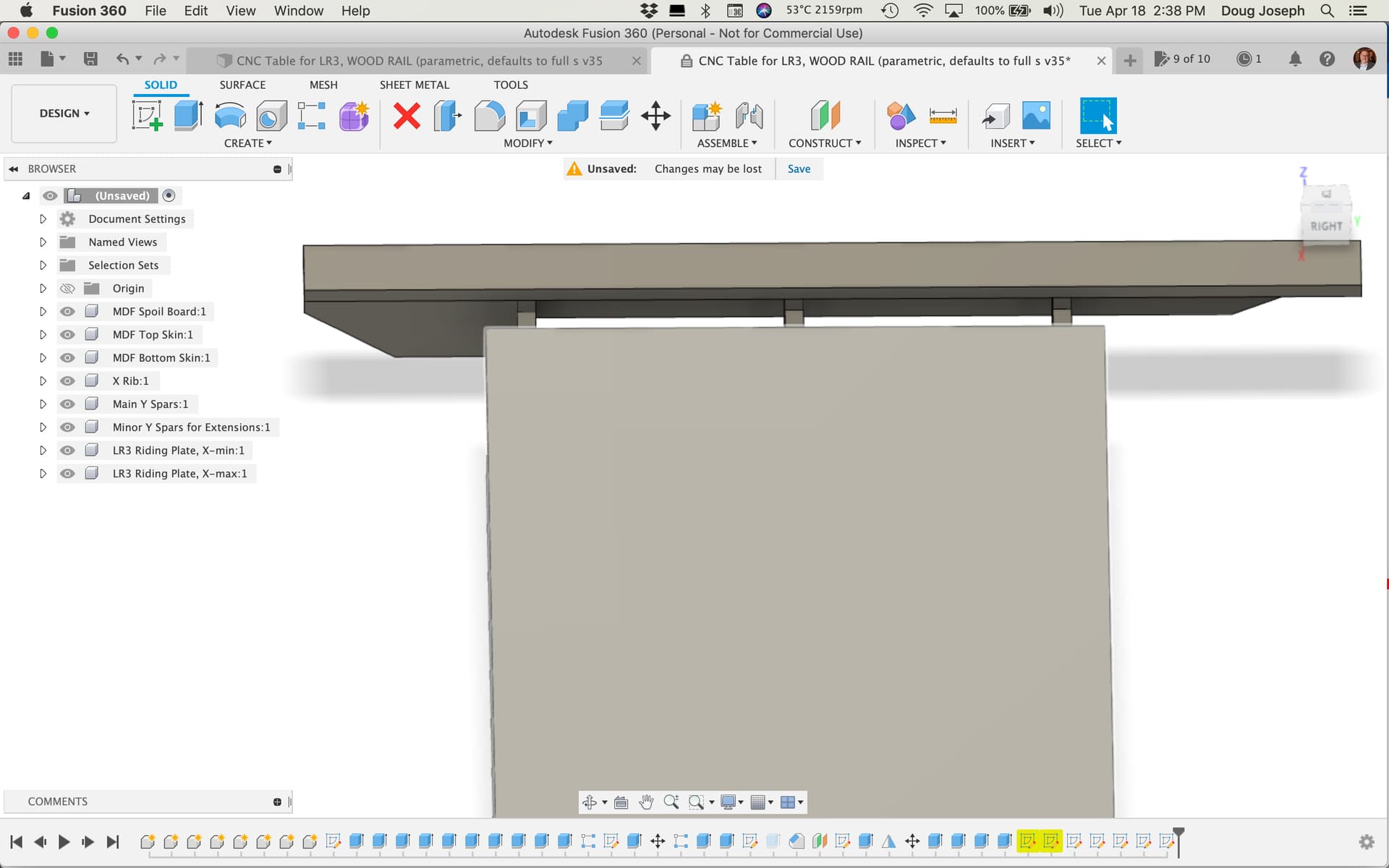
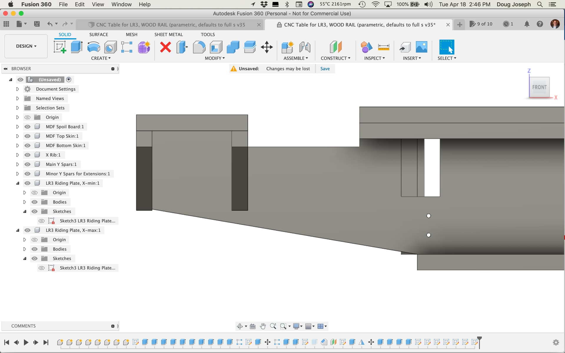
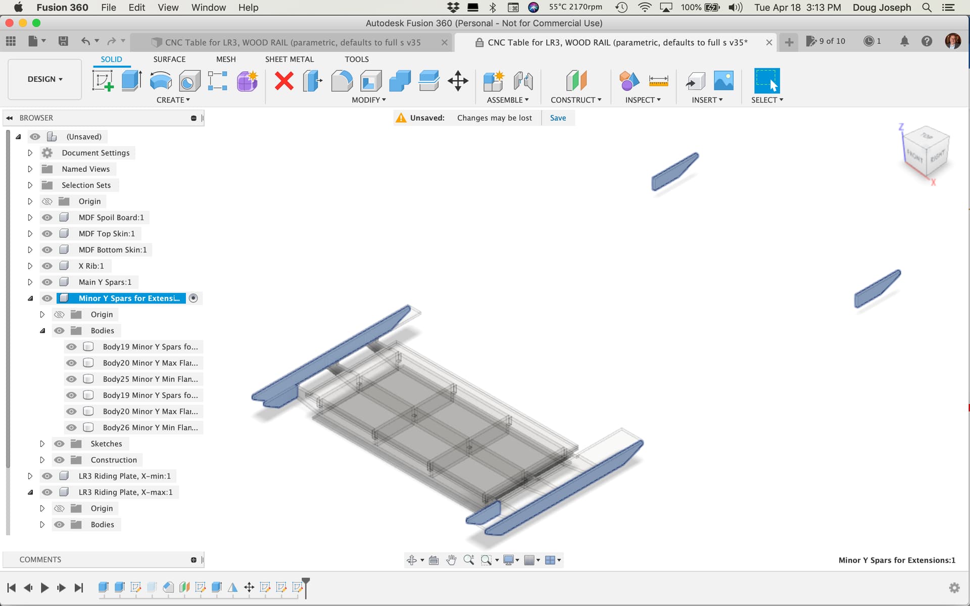
3. While the slot cuts in the X-ribs (for the Y spars to fit in) seem to have shifted appropriately (yay to me), the location of the Y spars themselves did not appropriately shift (boo to F360).

As seen here:

and here:

…This needs fixed by moving the first one, and having that movement be in the timeline prior to the pattern step that “repeats” the one on the left to create the other Y-spar bodies. :slight_smile:

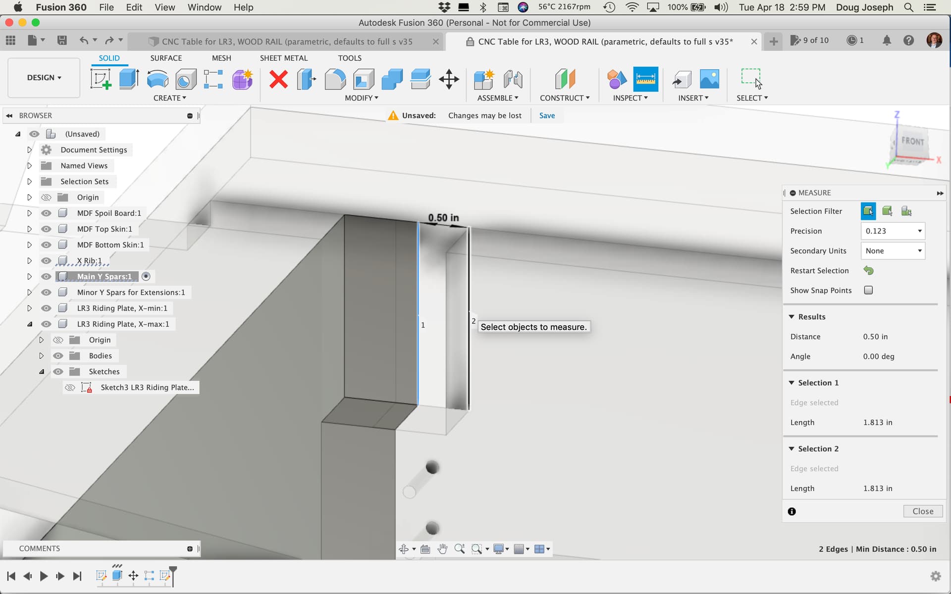
To measure the distance by which the one on the left needs moved, press the “i” hotkey, and click on the lines as shown, letting us know it’s off by 0.5". This make sense, since we shortened the usable width by 1" — and that 1" gets divided “by 2” (i.e. on both sides of the table).

… And finally, to fix that,

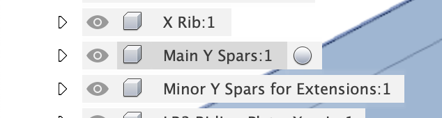
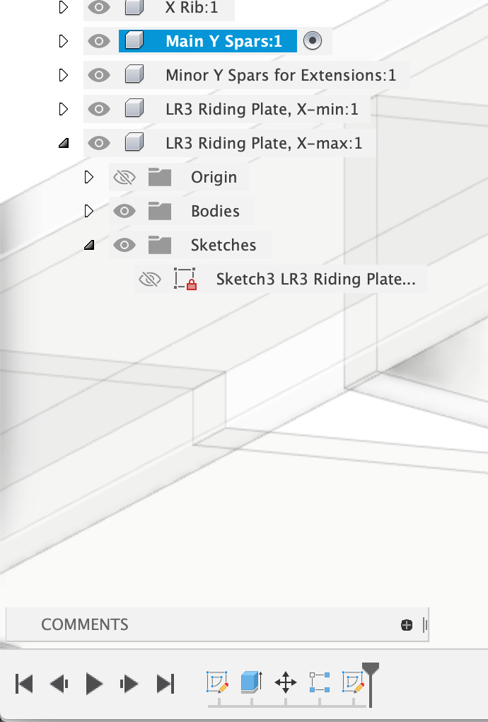
…first activate the component named “Main Y Spars” by hovering over its name:

Screen Shot 2023-04-18 at 2.54.12 PM

…and then clicking the radio button that appears:

Screen Shot 2023-04-18 at 2.52.36 PM

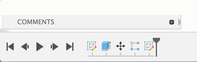
…Note that this will give a filtered timeline history that shows only history steps related to this component:

Screen Shot 2023-04-18 at 2.55.53 PM

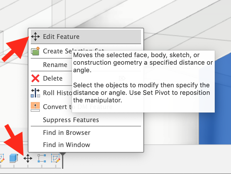
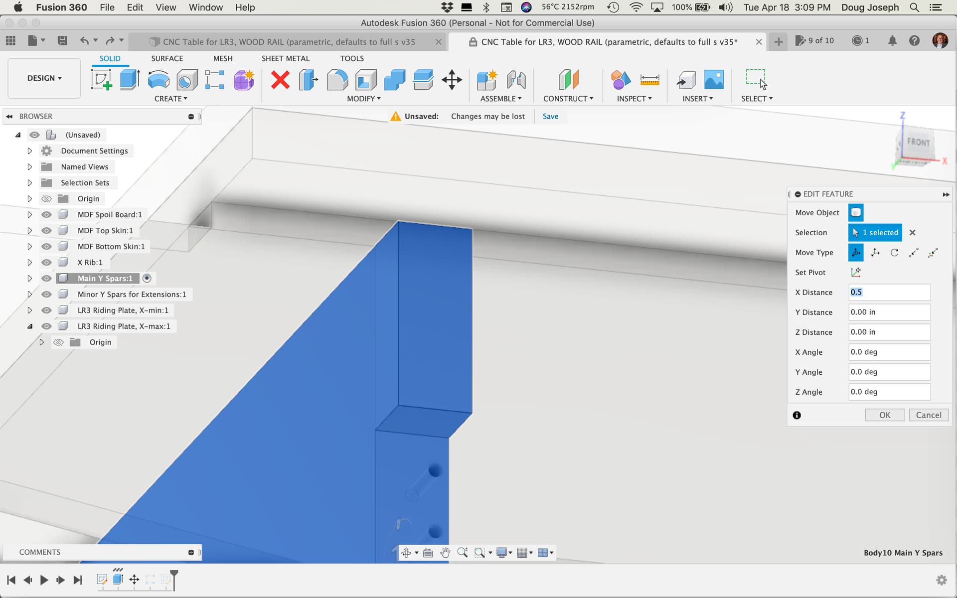
And the “move” icon in that history can be right-clicked and edited to input 0.5"

— note that for some reason (i.e. in F360 the move steps seem to not be parameter driven, despite a parameter having been used in the original move.), the previous move’s distance parameter is not shown as an editable bit of history. Any new inputs are seen as in relation to zero at the current location, and the new move results in a “cumulative” move distance, in which the newly inputted amount results in a new move based on the current location. I am disappointed that this is how F360 seems to work, and it’s the reason I have not yet figured out a way to avoid such move “fixes.”

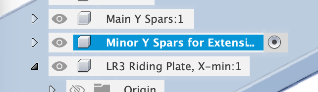
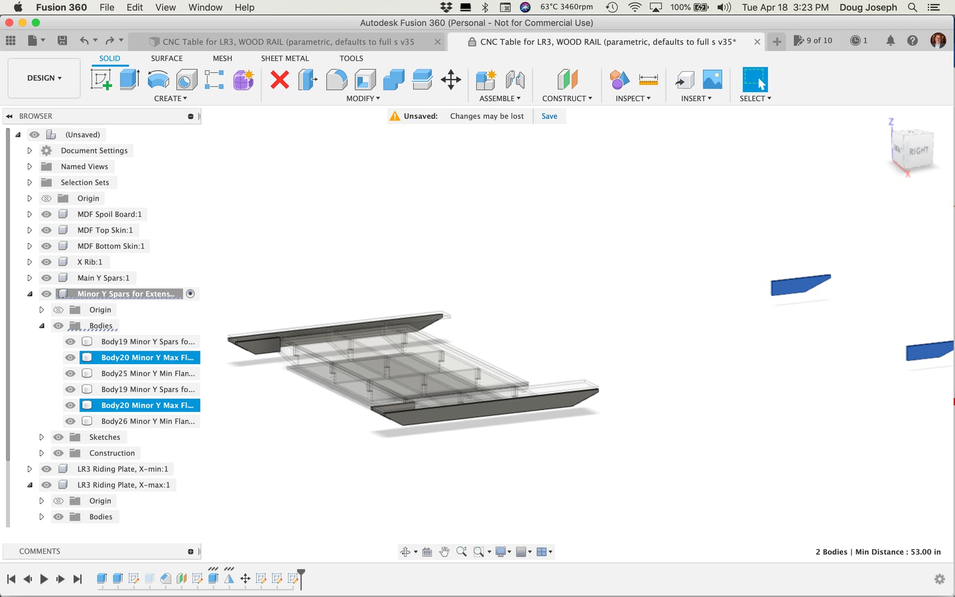
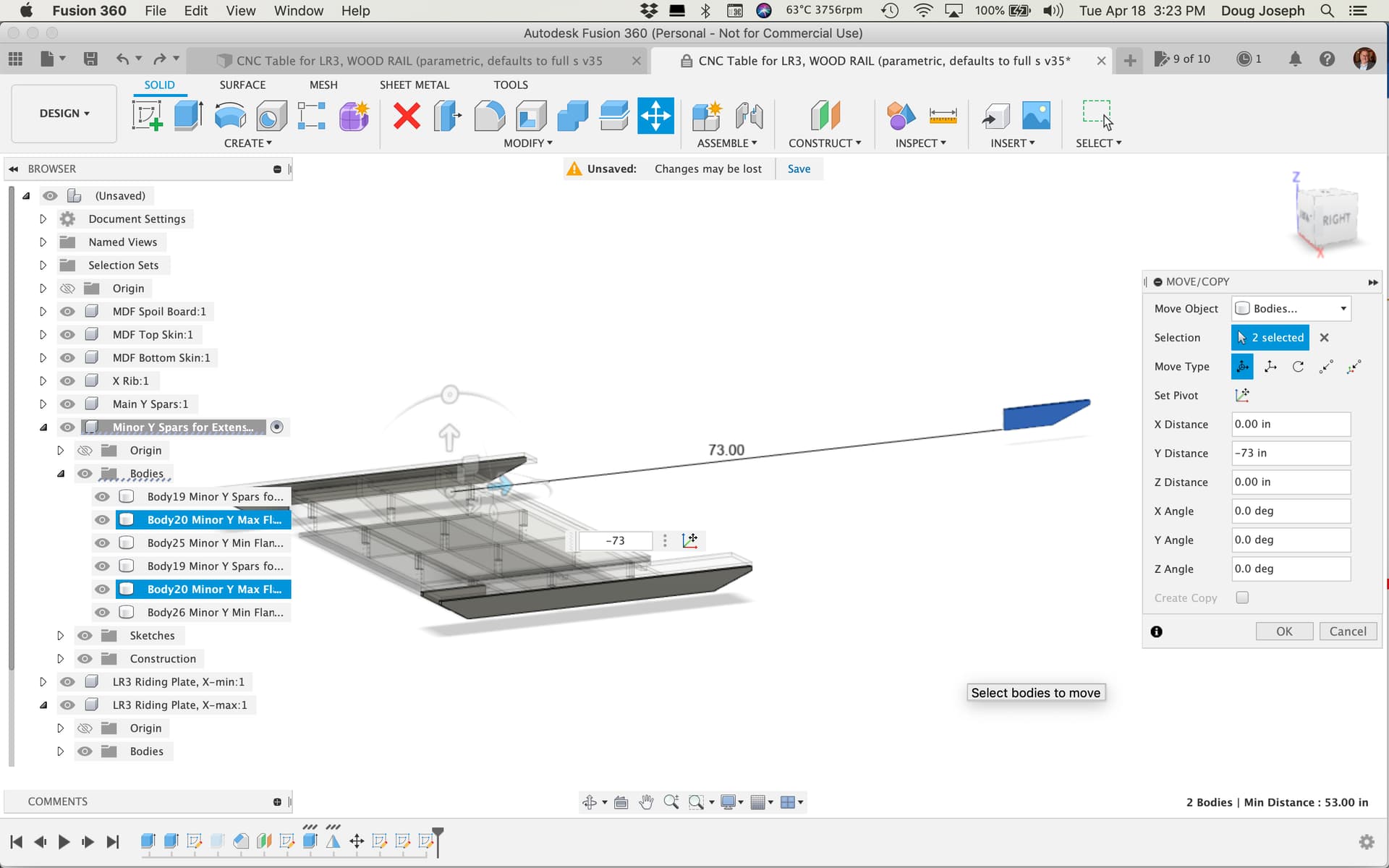
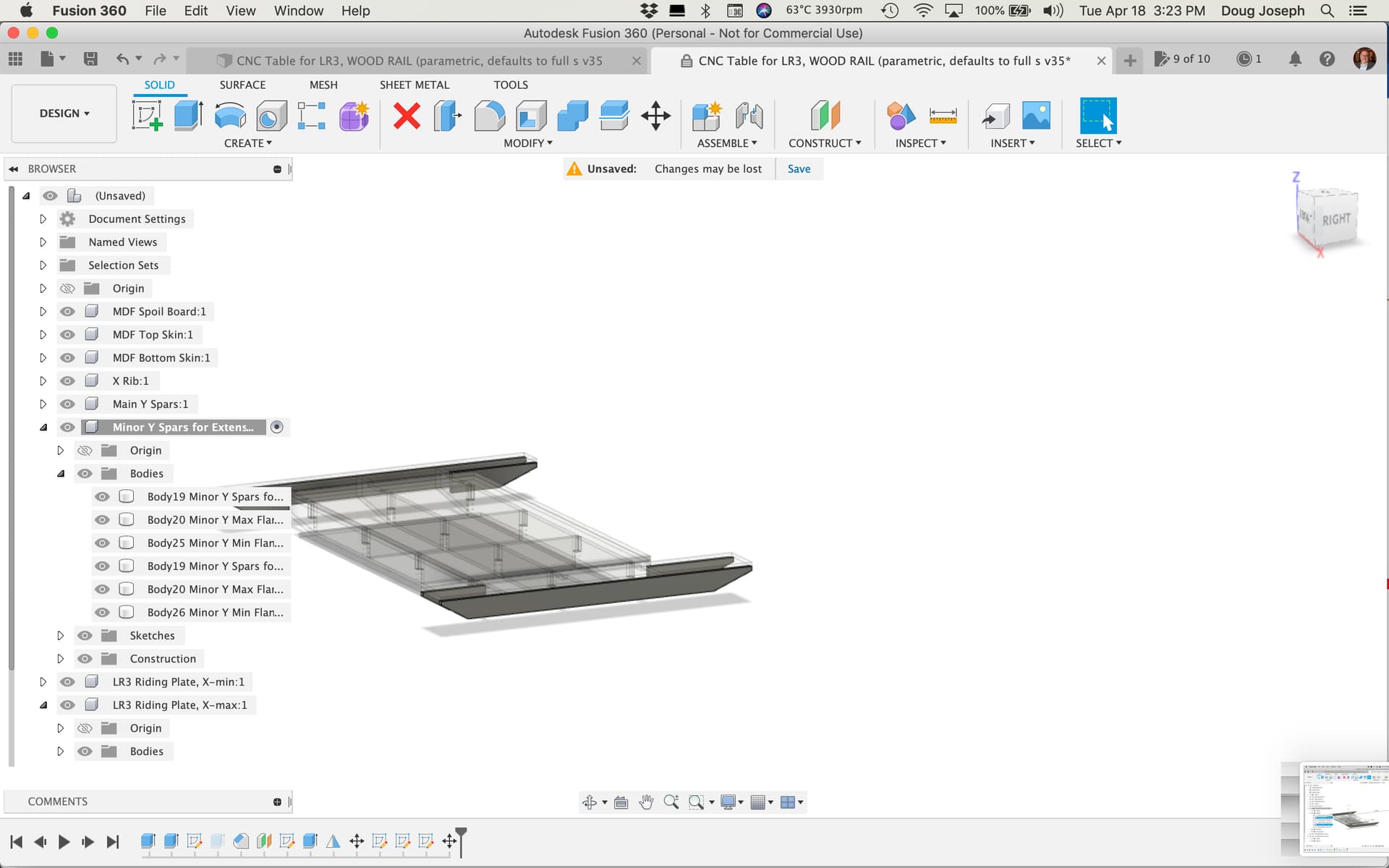
4. This step is similar to #3 step above, but this time activating the component named “Minor Y Spars for Extensions” in order to move the two bodies named “Body20 Minor Y Max Flange” and “Body20 Minor Y Max Flange (1)”. This distance by which they are now off is 73". (Used “i” hotkey to measure.) A difference here, is that these flanges being out of place seems due to a sketch element (somehow) not honoring the change in params, despite the fact that the rest of the “Minor Y Spar” elements changed as desired. This means the flanges being out of place is due to a sketch issue, and not due to the “moves in history are not parameterized” issue. Bottom line: there is no “move” icon in the history to edit. Simply highlight the two bodies, press the “m” hotkey" and input the 73" in the right direction (in this case negative, so -73").

BEFORE:

Highlight the two bodies:
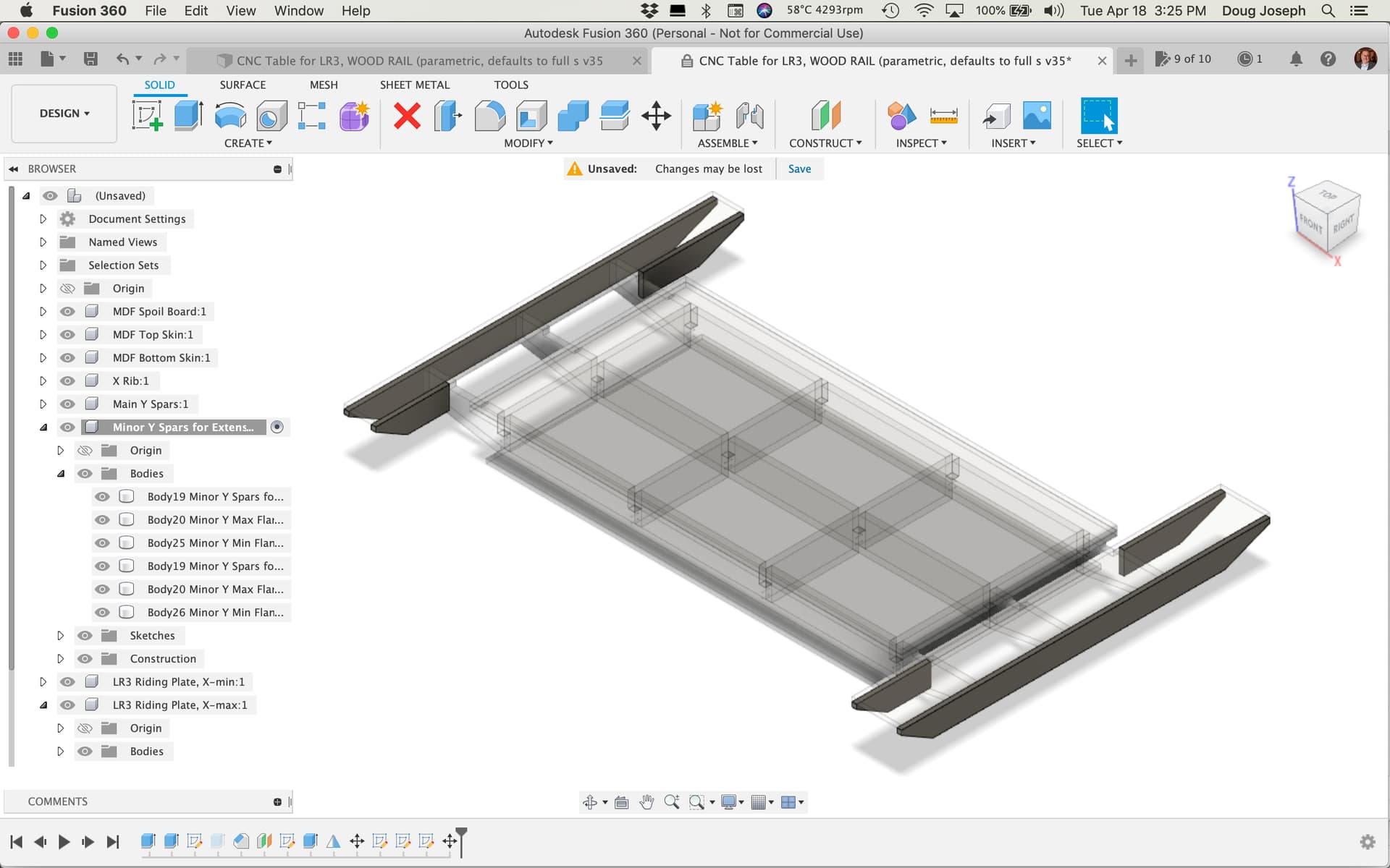
Input -73:

and…

AFTER:

Now, the good news is that I did all these steps as I went, so I can now save a copy and provide it for you. I will probably make a new post with that attached. If so, I will edit this post to add the link.

1 Like

In relation to my last post, above, did you indeed want the X-gantry on the 48" axis?

If so, I can save a copy of my steps to produce it. If not, I could redo the fixes, with the values in the two top params flipped.

@vicious1

Was just working to improve the parameters and the resulting functionality, and wished for a way to export / import params. Found this “app” for doing so:

Worked a treat. Linking both for record here and in case it helps (if you don’t already have something like it).

Interesting, that might actually help with sub assemblies. That is Solidworks default behavior, it looks for a sheet when it builds. More of what I am used to.

1 Like

I wanted to search for all expressions (aka formulas) where a certain param was being used. Opening the list in Excel made it easy to do!

1 Like

For more parametric CNC-cut tables for LowRider v3 (full sheet+): 3.625", 6", and 8" tall versions — click here: More parametric CNC-cut tables for LowRider v3 (full sheet+): 3.625", 6", and 8" tall versions

Thanks, that’s all great help.

Re the brace differences, I was more talking along the Y-axis and slotting together rather than lots of screws.

Re the rail widths, I did look at that and was a touch concerned about going wider towards the centre of the table and potential clearance issues with the vac shield etc but it looks like 10-20mm would be safe.

Re the metric conversion, I was able to change the units with ease by right clicking on the document settings and changing to mm which worked fine for overall dimensions. but when I tried to adjust the values in the change parameters section to match local material thickness etc is where I ran into issues as that all stays as inches, my work around was to convert my figures to inches but it seemed to create rounding errors so when checking final dimensions things like overall width weren’t whole numbers. (Im pretty green when it comes to fusion360 so this could be 100% user error)

1 Like

Hey, regarding the steps I mentioned before… I had made a newer version of the table that has its parameters interacting with one another a little bit better. So I whipped out two more versions of the table, one at 24" x 48" and one at 48" x 24" — here’s the download link: