Thanks Doug for quick fix of thickness and 16mm boards will be plenty strong!
So how do I combined them on a sheet for cutting them all at once. I use Estlcam and CNCjs for compiling and cutting. My LR3 is not finished yet but getting there slowly!
I did built this small DIY 3D Printed Dremel CNC By Nikus
An excellent little CNC to start with to learn the basics of CNC milling.
Since I’m not a CAD type of guy more a hands-on and hardware dude I not sure how to compile th ribs and spars to a single board and would humbly ask for help with that?
Thanks in advance!
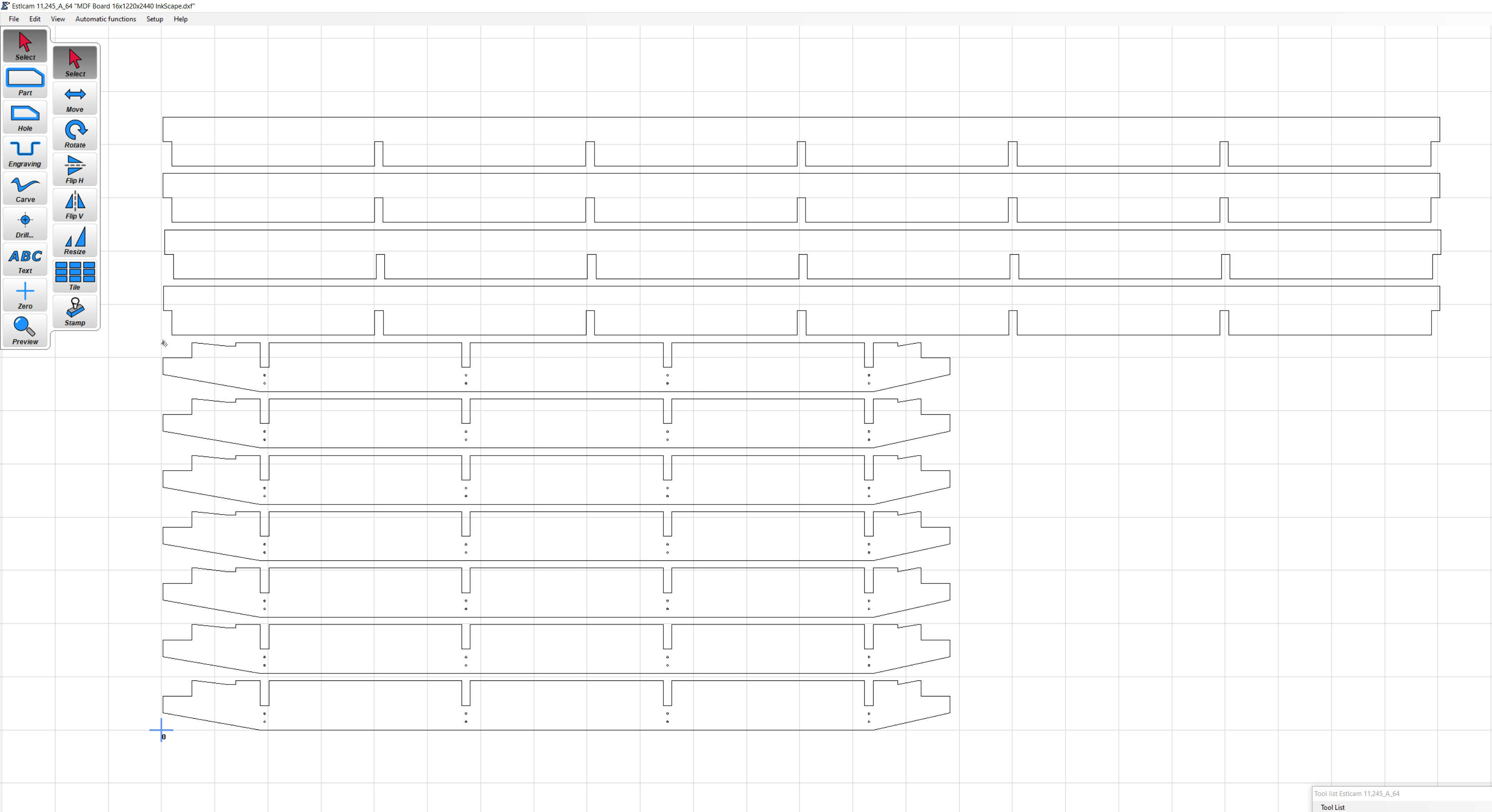
Usually it is done by using a vector illustration program, importing the individual DXF files, copying and pasting as needed, and moving them around on the screen, and then exporting it all as either as a scalable vector graphics file or a DXF file. And then that gets imported ESTLcam. There is a free vector illustration program called Inkscape. Paid programs include CorelDraw and Adobe Illustrator.
Do you want me to give some time for you to try to do that layout yourself? It’s a good skill set to have as part of your workflow on the CNC.
Each profile shape that you plan to cut as a separate part, in this case, ribs and spars, should be far enough apart that there is more than one “bit width” between them.
Also bear in mind that on this, I started by setting the page size in the vector illustration program to be the same size as a full sheet of material (in my case plywood, but you could size for MDF). That way, as I was placing the content on the page, it was mentally the same as placing the parts on a sheet of material.
If you are interested in an automated placement of the parts onto a given sheet you can also take a look at DeepNest, which is doing a really good job to efficiently lay out all your parts to minimize waste.
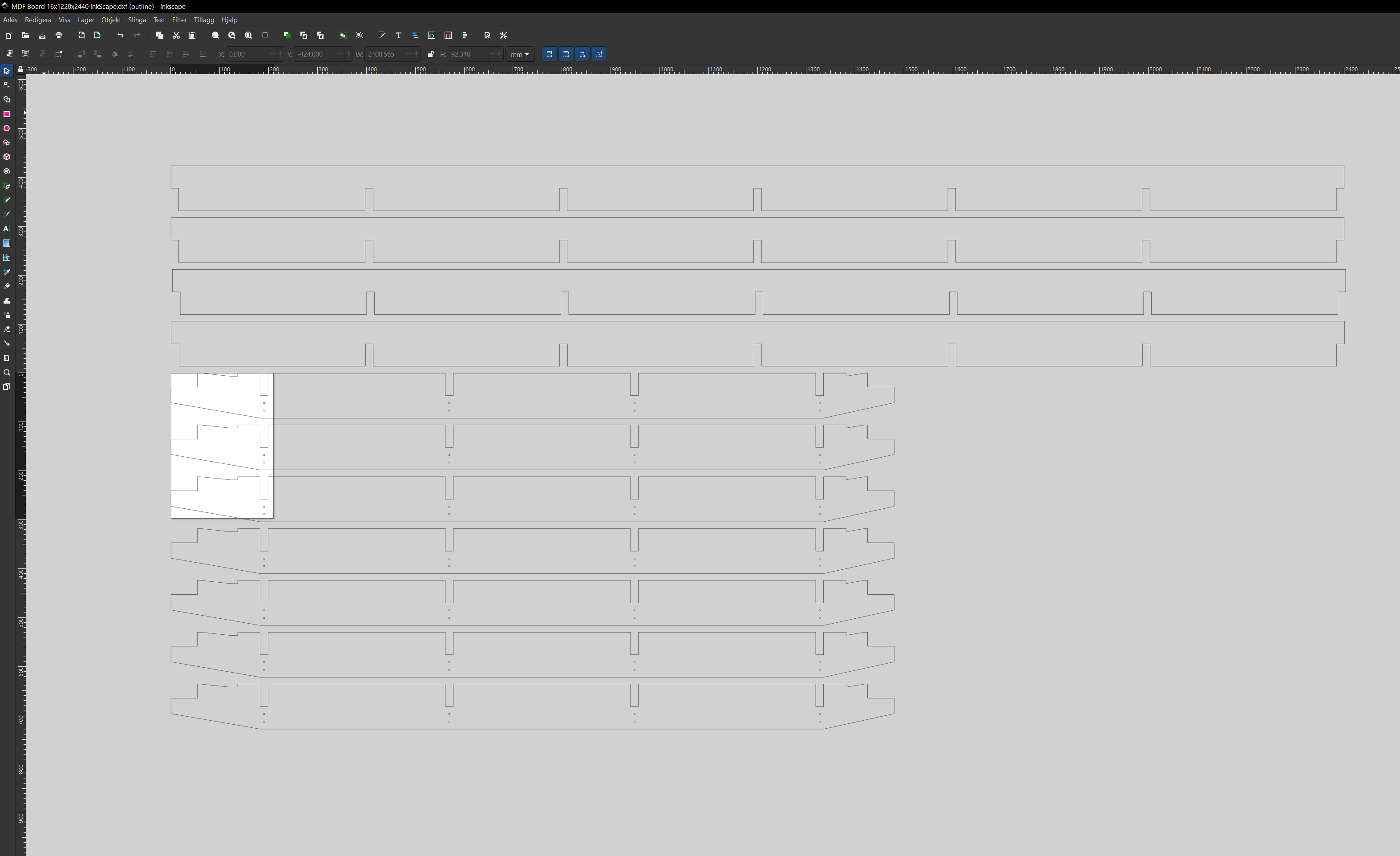
This is what I was able to do in inkscape. No idea how to get rid of the A4 sheet, as well as how to make a standard 1220x2440mm (48"x96") board. Of course it doesnt matter in Estlcam but it would look neat.
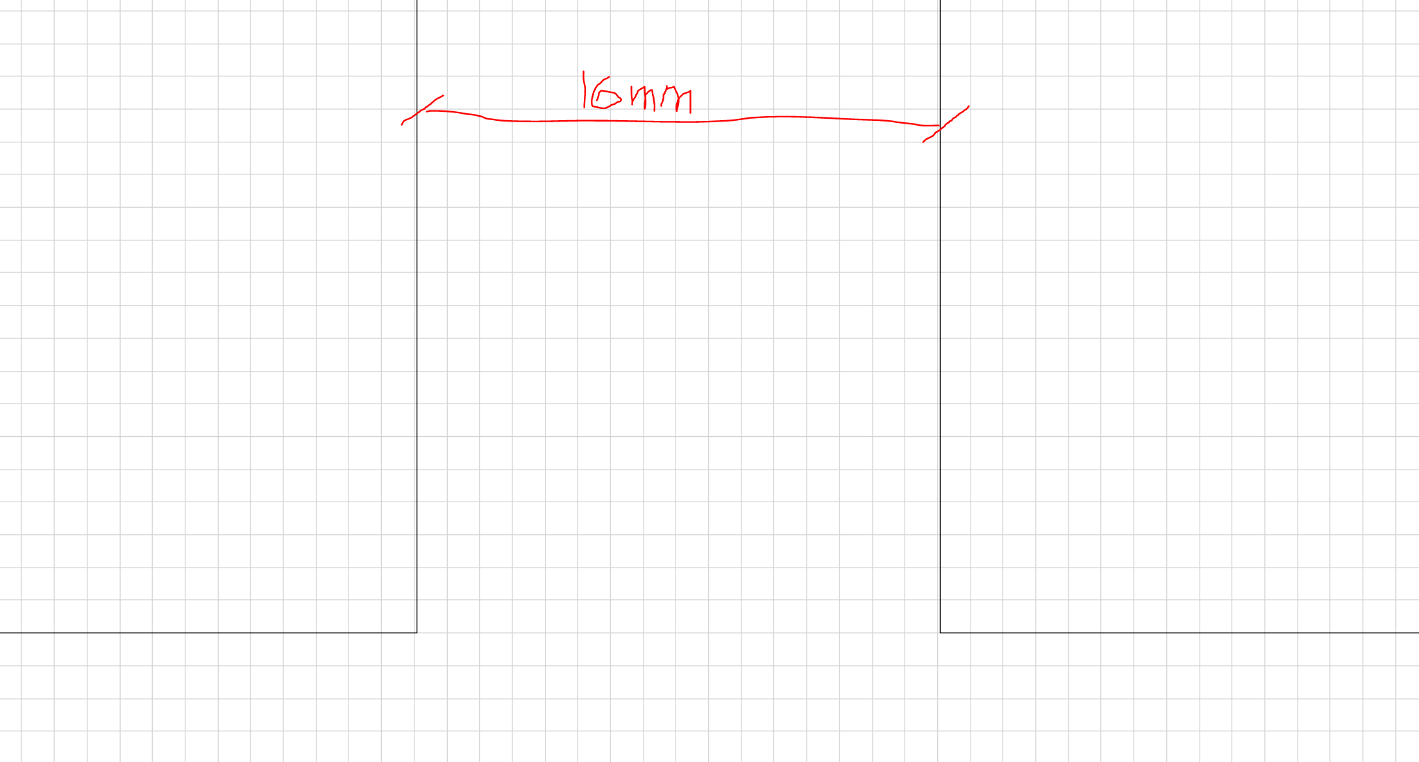
It is 14mm between the parts that should be enough for a 1/4" straight bit.
Make sure to test for proper slot width for your cross joints - or there might be a lot of sanding and probably cursing involved! And also please remember to add overcuts/dogbones so the corners fit completely! The 1/4“ bit can not cut the 90 degrees at the bottom of the cross joints!
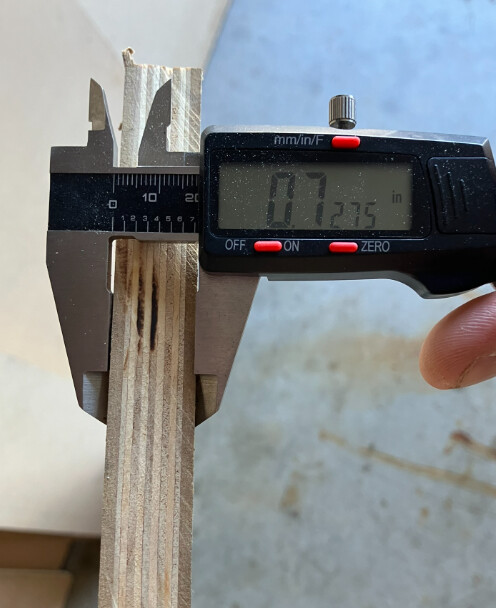
Yes. Measure the MDF with calipers to make sure its actual thickness! And print tests until you know the cross lap joints are working like you want them to. You can take part of the design in Inkscape to make the test. Just two squares, each with a notch for the joint.
Yes, definitely this as well! Overcuts (“dogbones”) are done in ESTLcam during setup of a cut.
Are you getting 49" x 97" plywood at a big box store, all I can find is MDF at those sizes in 3/4". Was wondering if my 48" x 96" would work and using the super struts on the sides somehow
My plan calls for the normal size of plywood, and allows for the larger size of MDF. It calls for cutting ribs and spars from 48 x 96, but is designed to allow 49 x 97 MDF sheets to attach for skin. Note that I was able to find 49 x 97 and 1/2 inch not just 3/4. If you cannot find that size in 1/2 inch then you could attach the smaller pieces or go ahead and go with thicker one, but the thicker one is going to make the bottom unnecessarily heavy, and for the top, while it could serve as both skin and spoil board, I hate to see you have to attach spoil board permanently as a skin, because it would not be disposable in the proper way.
If you were talking about what you plan to cut your ribs and spars from, and please note that Ryan indicated MDF is better for the ribs and spars than plywood is. Some have chosen not to use MDF because of concerns about high humidity, and went with plywood anyway. If you are able to cut 3/4 inch thick ribs and spars from the larger sheet of MDF, then the design could be modified so that your spars were slightly longer, and your ribs were slightly wider.
Yes, this not only can work it is how the design is set up. The table you see me make in my “full sheet torsion box, part 2” video is cut from 48 x 96 plywood, and I attached slightly larger 49x97 MDF top skin and spoil board, and I attached metal struts to it. I attached OSB for bottom skin, but if I had to do over again, I would put the half inch MDF for bottom skin, and the OSB for the top skin. I think I like having the MDF spoil board attached to OSB better than having it attached to another sheet of MDF.
I want to do this (Once I get my cnc running of course). I already cut it to size to a small 6 foot table I had in the garage, but think I am going to pull the pipes and re-do it in a correct size. Then I can build a proper table like this, not my butcherblock hack job.
I’m going to start building this sweet parametric table you designed for the LR3 I’m in the middle of building. I have a couple questions for you if you have a chance. (They’re probably all answered in this post, but my self diagnosed ADD is making it hard to read the whole thing today…)
I have a good supply of 3/4” Hybrid MDF/Plywood that I get for free. (1/2” ply with 1/8” MDF on both faces.) Is the Fusion file parametric enough that I could use this material as my permanent top skin and waste board?
If I go with the Unistrut version, would it be possible to substitute 1.5” square tubing for the 1.625” square Unistrut. Is the Fusion file parametric enough to accommodate that? Again, I have access to a nice supply of 1.5” square stainless steel tubing (again free). I was thinking of drilling screw holes on one side and access holes on the other side to install it on the table.
Do you think it’d be possible to cut the pieces on my MPCNC Primo in stages? My primo has a work area of 28x28”. I have this idea of cutting then shifting in the y-direction then cutting again. In my mind it seems plausible and should be as simple as splitting the DXF file in a vector program.
I know you say in the post that you would provide the DXF’s if someone reaches out to you, but I’d like to try it myself. I’m not very experienced with Fusion360 and I thought it would be good to try my hand at it again. (I’m more of an OnShape designer and I hate to admit when I get frustrated with sketching in CAD, I often do my 2d work in Inkscape and import it as a DXF into OnShape.)
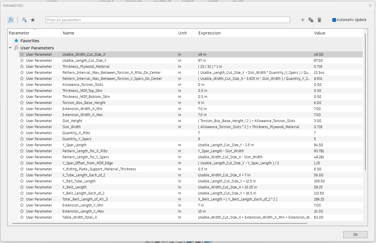
That should be no problem. If you click into the list of parameters, one of them is named something like plywood thickness, or some such. You can simply set that one to the value that you measured with your calipers.
Once you change a parameter and save the value, the model should update pretty much instantly.
There are parametric “part” sketches that say in their names that they are for DXF export. you can simply right click on those sketches and export as DXF.
The model can certainly be tweaked/edited to accommodate the slightly smaller square tube that you were talking about. Another way to possibly approach this would be to simply use shims/strips as spacers to position the square tube out a little bit and up a little bit. It’s certainly doable.
It’s possible. I don’t know that I would say convenient or advisable. However, you would have to decide on your own which way seems like more headache to you, doing a tiling method on the smaller CNC machine, or cutting your torsion strips with a tablesaw and adding your cross lap notches with a jigsaw etc. or putting some full sheets and strips on the floor of a flat area to create a temporary LowRider table for bootstrapping.
That can certainly do the job. No doubt about it. I have mostly used a 1/4 inch single flute up-cut end mill for cutting plywood. But a 1/8 inch can certainly do it.
Fusion is a real CAD users program and still too expansive for a hack like me! I found the parameters list but I can only modify name/expression/comment. I can’t figure out how to change the actual value.
I can only find the version with the wood roller rail on your website. Do you have the Unistrut version available somewhere?