Sorry for confusion on that. The situation with fusion 360 and parameters is that it needs a unit specified. So the thickness in that case was 23/32, and in order to get a unit on that I put it in parentheses and then multiplied that times 1”. So you need to express the thickness in a way they can have a unit applied. If you have measured with your calipers in millimeters, then maybe you could run a conversion from millimeters to inches and specify that, but make sure you put the inches for units.
1 Like
Awwyeah, that worked!!
If at any point I start becoming a nuisance just tell me.
- Should the final waste board height be slighly higher that the riding surface?
- Before I go to far, would you be friendly to the idea of sharing the version that uses the Unistrut drive surfaces?
1 Like
In the normal set up, the top of the spoil board is the exact same height as the riding strips that the LowRider is riding on.
My designs have the spoil board slightly higher so that if I surface the spoil board several times, as it gets thinner it approaches the normal, one to one congruence between the spoil board and the riding plate.
Regarding the other table design that is set up for metal struts, I shared that on my website. The website also has some documentation that may be helpful. If you go to the website and you are on the newer of two pages, there is a link at the top of the newer page that links back to the older page. The design you’re looking for may be on the older page with the documentation. I am on my phone and away from home right now, but if I can locate a link, I will post it.
.
1 Like
Here’s a link to the newer of two pages on my website. At the top of the page is a link to the older page that has documentation. There may be a metal strut design on both of the pages or only on one. It’s been a while since I did this and it’s not all sharp in my memory right now. Hopefully this link helps though.
https://design8studio.com/for-lowrider-v3-cnc-cut-table-dxfs-for-cutting-f360-archives/
1 Like
Thanks!!!
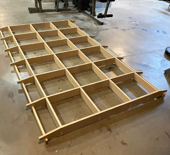
That makes sense about the spoil board height. I will post pictures of my progress and finished table. It’ll probably take 2 months to finish. I am going to try ‘tiling’ on my MPCNC Primo to produce the parts. If I start banging my head against the wall I’ll switch to the ‘bootstrapping’ it a temporary surface.
BTW I watched some of your videos on the table construction and I admire the fact that you still use a corded drill. It seems there’s this idea that corded tools have become obsolete, which is ridiculous.
Thanks again Doug!
1 Like
Hi Doug, I found the zip archive for the strut version on the older page as you said. I was able to change the parameters for all plywood parts to now be 0.73". For some reason there was a shift on the rails to the spars that created overlap. I was able to repair that with a ‘conincident’ constraint, which made me feel like ‘hey, I can do this Fusion thing!’
Then I set to adjusting the Unistrut dimension to 1.75" square stainless steel tubing (I was mistaken in my earlier post when I said it was 1.5"). I was able to adjust the parameter and the Unistrut profile sketch but I could not figure out how to move the minor spar and the new 1.75" steel riding surface, which then made me feel like ‘hey, I’m way out of my depth with this Fusion thing!’.
Anyway, I cheated and exported the DXF and made the last of the adjustments in Inkscape. Through the whole process I somehow lost .125" from the stock rib length of 58.25". I massaged it a bit and did a layover of your stock DXF to my modified DXF and I’m confident it’ll work.
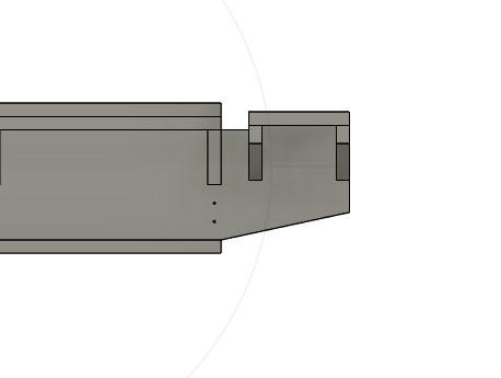
Quick woodworking question for you though. If I remember correctly you used a 2 flute 1/4" endmill to cut your MDF parts, which must leave a 1/8" radius on the inside corners. Do you jigsaw them out or knock the hard mating corners off with a sander or roundover bit on a router. It seems to me that easing the hard mating corners would be easier than jigsawing.
As always much thanks!!
1 Like
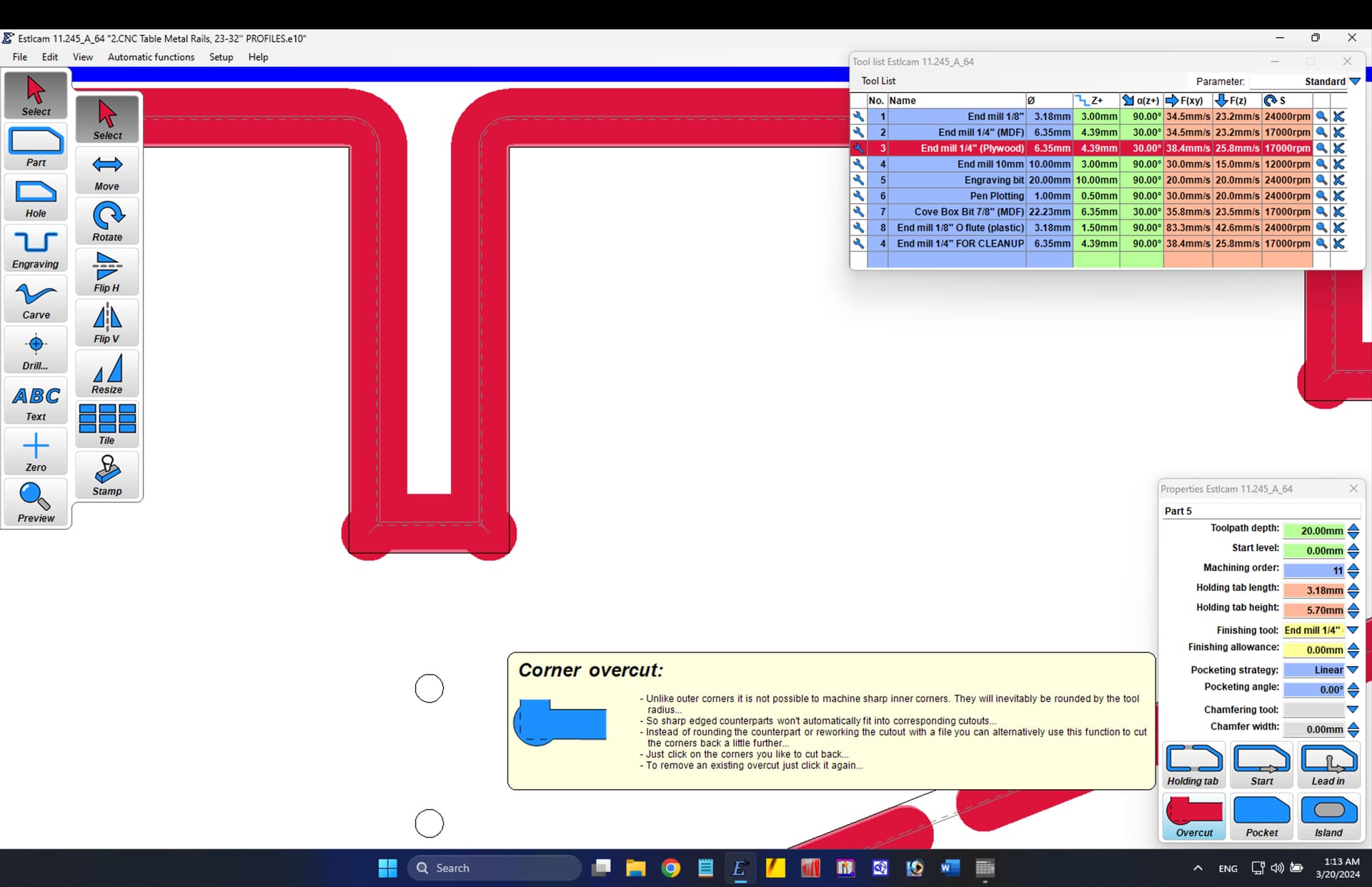
There is a feature in ESTLcam called “Overcut” or “Corner Overcut” and that everyone usually calls by a nickname of “Dogbones” — and this feature will eliminate any inside corner issues with bit radius. Here is a screen shot of a cut, shown selected, and the inside corners prep’d for overcuts, and the GUI interface button for overcuts shown highlighted and its popup explainer:
Happy to help!
1 Like
I cannot find the download for the full size table with metal struts, all the downloads available say wood side rails. The closest I got was the web only preview of the metal strut table.
Currently making designs in sketchup for a low cost 3 machine micro factory and am hoping to import or rebuild your table plans in sketchup to modify.
Does this post from a week ago help? The link at the top of that webpage leads to an older web page that has the table design for metal rails.
The table design for metal rails was done in Fusion 360. From there is could exported for SketchUp format!
Yes. Measure the MDF with calipers to make sure its actual thickness! And print tests until you know the cross lap joints are working like you want them to. You can take part of the design in Inkscape to make the test. Just two squares, each with a notch for the joint.<
How do I do this? I am finding Inkscape very frustrating.
Sorry for the frustration with Inkscape. May be doable to create tests with ESTLcam (are there primitive drawing tools in it?) If I could find time I could add a sketch for tests to all the various files of the different size tables. In CorelDraw, one could simply import the rib (or spar) and draw a rectangle around the part with the notch, and highlight the rectangle and click the shaping tool option to “intersect with” and tap on the rib. This would give a part that could be cut twice, and then use the two to attach to each other and test the cross-lap joint tightness.
Hi Doug! I just watched your video of the heart box cut on your new LR4, NICE!!
I’m going to be shifting gears on the LR3 that I had about 90% complete and repurpose as many of the parts that I can to an LR4 build.
My big question is, We’re you able to use your existing metal rail table (the one you built for your LR3) with your new LR4? The only thing I needed to do yet was the top & bottom skin, the waste board and the rails.
As always thanks for any pointers you can provide.
Also, I agree with your video, Ryan did it again, another great design!
1 Like
Thanks! That is my goal, and what I am working toward. If you have not seen my build log that I recently started, do check it out as it has information pertaining to this. I am working to get to the place that I can do test cuts with a new full-size LowRider 4 — on my existing table that I used for the LowRider 3. As soon as I can get some test cuts made That will either validate or invalidate my table extenders that I am attempting to use.
1 Like
Hello Doug,
Would you care to update the tool specs for the LR4? I’m sure, without pushing limits, we could get the parts cut a tad quicker. (basing on the videos you and other beta testers posted)
I’m hoping to bootstrap a table later this week. My initial thoughts where to buy 10’ prime 1x4 and 1 x 6 MDF boards for the running plates. Install the rails and belts to them (in final positions) then square them up on a stage floor and bootstrap the rails and spars. That would save me from worrying about a seam and would speed up the build process.
Thanks, Doug!
1 Like
Rather start off with conservative values than to start at the maximum, I guess. Messing up a whole sheet would not be great. ![]()
3 Likes
Totally agree! Especially at $65/ sheet. Just curious what conservative is for the LR4…
1 Like
You might check out cabinet supply shops around your area. I just picked up 3/4 MDF for $33 a sheet, 1/2" Paint grade birch for $33 a sheet, 1/4" Paint grade birch for $16 a sheet and 1/4" MDF for $13 a sheet. Home depot would have been MUCH more expensive than that. So worth doing some googling and phone calls. Worst they can say is no LOL
2 Likes
I ran 2400mm/min in plywood (that is a lot harder than MDF) at 5.5mm DOC when I had problems at 3500mm/min (my endmill was dull which I hadn’t realized back then). Beware I am using a 2-flute 6mm endmill.
With a 1-flute 3.175mm I might try 1000mm/min, 3mm DOC. That’s what I cut my strut plates at when I wanted to be sure that it works.
1 Like
I would be learning the machine in foam and soft wood before jumping in all the way on expensive materials. What is conservative for the LR4 and what is conservative for a new user are different things. Start slow and work your way up.
This section on the Milling Basics page starts very conservatively but gives direction on how to increase speed.
https://docs.v1e.com/tools/milling-basics/#for-the-impatient
3 Likes
Totally with you Jason, and thank you!
I need to get a table built and I am bootstrapping it on a stage floor that I don’t have unlimited access to. With a student body of 2500, stage access is at a premium until I hit the build calendar. Then there is no time to be playing around with a new “toy”. So I’m trying to see what time I may realistically need to cut the torsion box parts so that I can then move into the shop and assemble the table . At that point my test will be in 2" XPS foam carving castle walls for a middle school production of Shrek Jr… I’m not rushing to carve mount Rushmore out of black walnut or african bubinga, I would just rather use the LR4 to cut the table. The 38.4mm/s just seemed very slow for a full sheet cut. I see this as a very straight forward 2D cut job. If im incorrect, I’ll just run the job the old school way, table saw, chop saw, and back to the table saw with a stacked dado … I can accurately knock that out in about an hour (taking time to make sure the lap joints are a tight fit…
I appreciate that you are watching out for me as there are a lot of absolute beginners here. As far as CAM software and CNC routers go, I am one of those…BUT as far as carpentry, electronics, and fabricating…37 years in.
Off Topic completely, but, we should have an introduction topic where we get to know each other, who does what, what eachothers skill sets are…etc…pics, videos, could be cool
2 Likes