2 Likes
Closer. I’ll see how this looks scaled to 40.5" by 60" cut area.
1 Like
One of the challenges with parametric designs, is that, sadly, in F360, “moves” are not something that have any in-built history of their own, and therefore cannot be parametric. This means if there are any standard “moves” of components or bodies within the document timeline, the whole project is thwarted from being 100% totally parametric. If you change a parameter then things affected by a “move” don’t adjust their location automatically. So after changing the parameter, you may have to measure how far the item needed to move, and move it accordingly.
Since part of the design I did, sadly, has a move or two in it, this issue arises.
Thus, it is helpful to know that when mutiple copies of a body or component are being created in a linear array based on the location of the first one, you only have to re-move the first one. For the Y spars, the first one is on the left from the front.
And sadly, sometimes the parametric parts actually move the wrong way. Very odd behavior, but fully parametric is very, very hard.
If something is not working, make small changes. Instead of making it 4’ bigger, make it 1’ bigger and see if it still works, then make in another 1’ bigger. That tends to work better in fusion for some reason.
3 Likes
I was also adapting the Metal rail table from Doug to my desired form factor of 1000mm x 1600mm cutting area. I ran into the same issue with the weird shrinking.
I THINK I managed to fix it by constraining the longer and shorter angled part going up to the rail with a custom parameter where I just entered the original length given in Doug’s model.
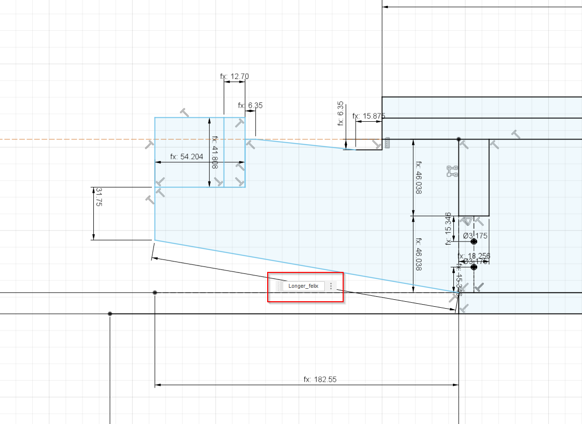
I say i think it solves it because I still have some measuring to do for my specific LR3 after putting the struts on yesterday and making sure the F360 model dimensions will work out in real life. Im also just learning F360 coming from Sketchup so it may be hacky but the table looks good with this modification.
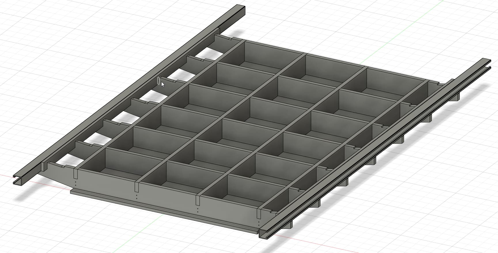
My planned table for 1000x1600mm (still debating metal/wood rails)
3 Likes
Thanks guys so much! I appreciate the information. It’s all helpful. I’m mainly interested in the DXFs, so I’m using all this to try and create my ribs and spars. The rest I can do on my table saw. (Let’s get real. I could probably do most of this on the table saw, but it wouldn’t be nearly as much fun. ![]() ) My painfully small Fusion 360 skillset is expanding slowly.
) My painfully small Fusion 360 skillset is expanding slowly.
2 Likes
One thing I wish I had done differently, was to not cut the width off the bottom skin, and not accordingly move the Y spars inward from the edges of the top skin and spoil board. In the recent 30x60 table design, I undid this. It’s not a deal breaker, I just wish I had those outer spars holding the top up right near the edge.
2 Likes
Hey Doug,
I just want to say thanks for desinging this and posting it.
I also want to say thanks for all the work and time you are putting into helping people with how busy you are due to the floods etc.
Chris.
3 Likes
I am just now editing the Fusion 360 archive files for the various sizes of tables I have offered, to fix a couple of things. I don’t yet have new files to upload, but hope to soon.
- I am making all the designs work without any “moves” in the history (since moves cannot be controlled parametrically).
- I want to revise the design so the Y-spars support the sides more closely.
PS: I have realized that a “move” can be OK if it is late in the history (near the end), and also does not have anything downstream of it (in the history) that depends on the “moved” item to calculate its own location.
3 Likes
Are dead links for me. 404 file not found
Will fix it.
OK, I fix those links. They are downloading for me now. Perhaps try again. Thanks for the heads up.
Yep, all good now ![]()
1 Like
I need a parametric table too. Can’t achieve flatness even in some parts of the middle of mine. Awesome Doug as always!
1 Like
@DougJoseph I’ve watched your videos a few times now as I’m setting up Estlcam to cut my table. When setting the tool path are you cutting these on the inside or outside of the lines? I would assume outside. In your video looking at your pieces as you pull them off it seems you had a slight gap between the cut pieces. But when I look at my Estlcam cut, it seems my cuts are going to overlap each other on the pieces. I’ve got my tool list set like yours were in the video.
The job’s profile cuts are always on the outsides of the lines. The more recent cut plans I’ve made available were set up with use of “common cut” — meaning the 1/4" trough cut as the bottom of one rib, is the exact same location as the 1/4" trough cut as the top of the next rib. I know that in the printing industry this is called “common cut” — and I don’t know if it’s referred to in CNC with the same term, but it’s how I describe it!
Hey, I’m back with an apology, and a change of course.
I actually recently cut a table that was setup with use of “common cut.” It works OK, you can do it, and it does have some advantages, but there are also possible issues. If the common cut has an unbroken stream of material on one side, with an already-cut gap in material on the other side, the bit can undergo a bit of deflection that causes a nub to remain uncut. Also, if any piece adjacent to the common cut is not perfectly far enough away, its profile cut can eat into another part not yet cut on the other side of the common cut line.
I’m planning on redoing the cut plans I offered, in order to back away from use of common cut.
Update: Please forgive my delay (a lot going on), but I finally got around to updating the DXF cut plans linked in the top of this thread, to avoid use of “common cut” efficiency, as it can lead to slight irregularities that are not optimal for torsion box ribs and spar parts. As of now the…
Fusion 360 archive files + DXF overall cut plans (and individual part cuts as well)
…shown in the original post at the top, have been updated to allow at least .375" between each part, so assuming you are using a 1/4" bit for cutting out the profiles, you should not have any issues that could arise from a “common cut” type layout.
Hi Doug!
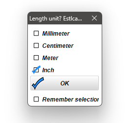
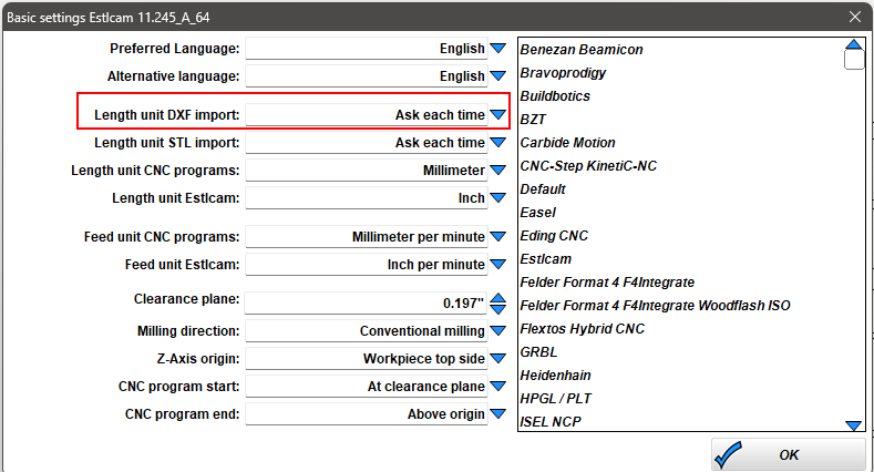
I like the table with the metal struts, but when I load the file in Estlcam this is what happened. The scale is very small the size of the board is 94mm x 48mm instead of inch.
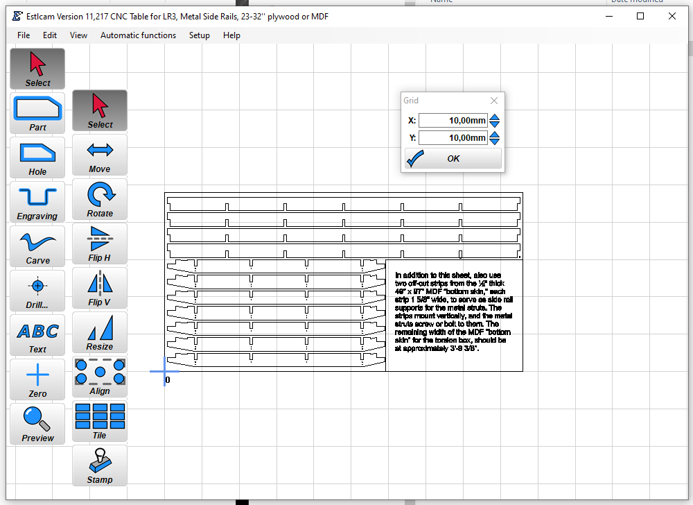
Also wish that I could get this table DXF files for 16mm board thickness.
Is strong enough and if using mdf is a bit lighter also is easy available thickness here in Sweden.
Thx in advance!