For us the usual logic is to have a spoil board the same size as the standard sheet available in the area. Since the MDF sheets available to us here are one inch bigger than a standard 4’x8’ sheet (in both length and width directions), we figure why not make the spoil board that size.
While having the spoil board be a solid single piece is common and perhaps desirable, there is nothing saying you cannot have a two piece or three piece. The “joint” where multiple pieces come together could potentially be an issue where a “seam” is not as flat, or edges are either slightly lower or slightly higher. But then again, surfacing can help with that.
You can do whatever you want to do. If I were there, I’d probably use 2400x1200 solid piece in the middle for the main spoil board, and perhaps put some “strips” around it to build out the remaining area. Please take some pics and post them!
I used slats on my builds, and cut/stacked them to function as tslots. They tend to pivot around the screws (which run down the centerline) when I snug down my workpiece. It would probably be better if I used two rows of screws closer to the edges. When I replace them, I’m just going to get some t track and put slats between them
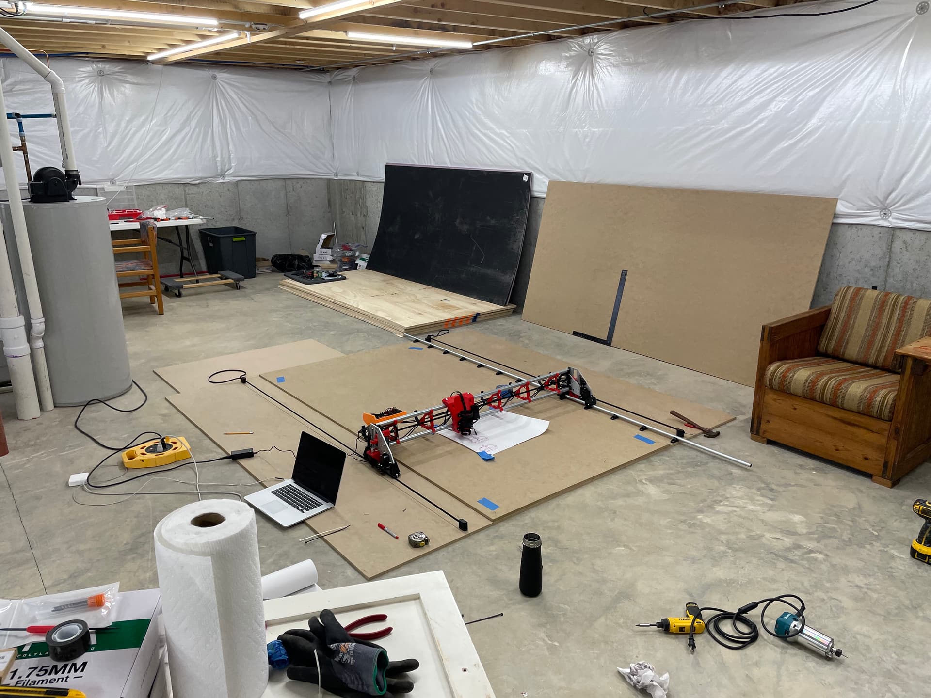
I’m likely going to build the unistrut version of this table, and since my gantry is slightly wider than “standard”, I’m trying to figure out how to adapt the design…
F360 noob query:
I’ll check out the links and vids about parameters that were posted way up in the thread, but was wondering: is there was a quick and easy way to keep the cutting area the same (49x97) and change the width of the X ribs to accommodate a slightly wider gantry (57.75")? Or will it involve more complicated manipulation? None of my initial playing around has resulted in the X ribs changing width in F360.
In the parameters for the metal strut table, it shows an X_Tube_Length of 56 inches. I assume that is the length of the EMT for the gantry, although your specs call for 56.1-56.5 inch EMT. My tube length is 57.75 inches right now. That would be a difference of 1.75 inches from the F360 parameter, or 0.875 inches * 2. Do I need to account for that extra 0.1-0.5 inches?
I figured out how to modify the sketch of the X ribs to extend just the ends that support the rails without changing the cutting area or Y spar locations (which is what I want to do). If I move each end of the rib away from the center by 0.875 inches - or whatever the value is based on my first question above - from where they started, would that accommodate my wider gantry appropriately, while still maintaining the X-min and X-max differential widths?
(Hopefully all that makes sense, let me know if it doesn’t…)
So, I’ve been busy with trying to recover from the house taking on water, and I am sleep deprived and a little foggy brained. Remembering what I did is challenging, but less challenging than trying to understand your question about it. LOL.
The X_Tube_Length variable is calculated from a formula — based on another variable, Width_Cut_Size_X, and adding 7 inches to it.
Width_Cut_Size_X + 7 in
However, the 7 is not an arbitrary amount. It was there simply so that one could tell at a glance how long the tubes need to be (at a normal minimum) in order to achieve the desired cut width.
In other words, the X_Tube_Length variable may not be utilized in any other formulas or calculations. I think it is not.
So, if you change that “7 in” distance in the formula to 8.75, then nothing in the drawing changes.
If you want to make the drawing actually change, then edit the other portion of that formula, the Width_Cut_Size_X part.
If you want to make the “7 in” part longer by just nudging the sketch edges, to make the table wider than it needs to be for the given Width_Cut_Size_X, then certainly you can do that. That would widen your gantry and increase your usable cut area. It would also slightly alter your rigidity (stiffness) for the worse, although it may be by an imperceptible amount.
Is it because you want more X travel range for the core? Or just don’t want to cut the tubes you have?
Let me attempt to simplify. I’m trying to avoid cutting the tubes already assembled in my gantry.
Let’s ignore all the parameter editing, because it wasn’t modifying the table the way I wanted. I figured out how to do what I want by editing the sketches. I need to know how far to move the rails out from their existing location to make my slightly wider gantry work. Therefore, I need to know what the correct reference X tube length is.
I did see that the tube length in F360 is formulaic based on the cutting area width. The formula calls for an X tube length of 56.0 inches for a 49-inch-wide cutting area. However, the images and text on your site where all the files live suggests a width of 56.1-56.5 inches. What is the “most correct” X tube length for the metal strut table design that I’m looking at in the F360 file?
So the difference between 56” even and the 56.x may be due to my file for my own table (with hidden belt) and the file I made for offering online. I think the range given was some calculation I did on what was workable.
One thing to remember is that the notches that hold the metal struts can be shimmed thicker or less to adjust where the gantry is riding. Also the location of the rail can moved a little bit.
Have you fully assembled your gantry so you know where its wheels are riding? That width measurement arms you with the knowledge you need to get the table right.
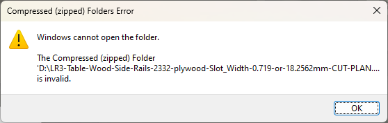
Attempting to download the F360 archive from your site seems to result in .zip files that my computer deems invalid. Attempting to open the F360 preview links comes up “unauthorized”
I tried the 24X48 one, and editing the parameters seemed to break it…
IMPORTANT NOTE: I included informational details in both folder names and file names, but on some computer systems, those long names prevent the files from being opened! If this affects you, then once you’ve made note of the info details, shorten all the folder names and file names. All the files open for me!
Try shortening the folder names and file names and see what you get!
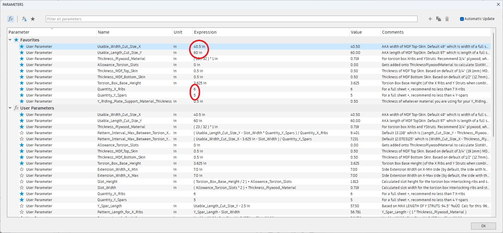
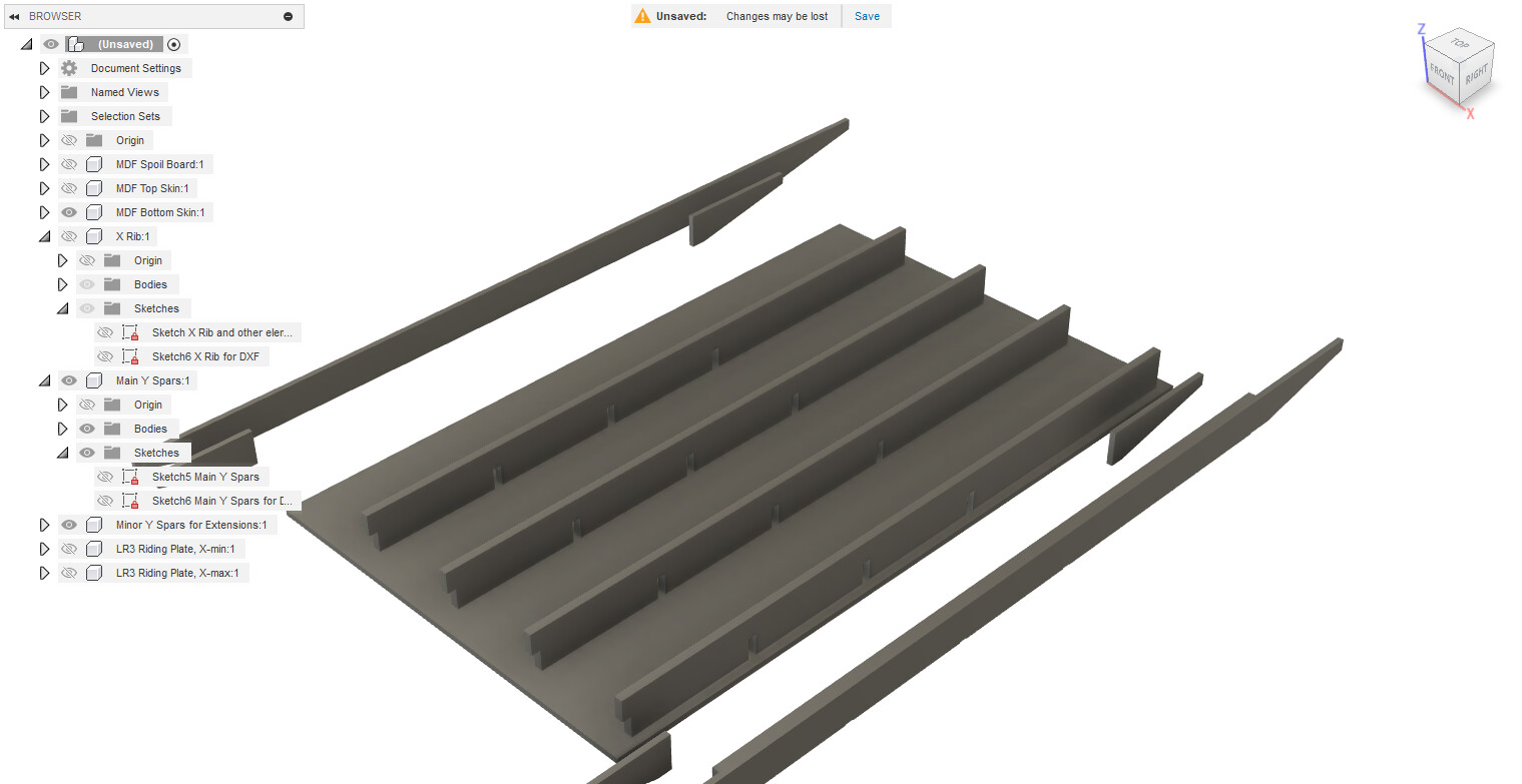
So the errors that I was seeing. I changed the parameters as follows: (Changed parameters circled in red.) Note that when changing the number of Y spars to an even number, Fusion gives an error. I assume that something wants one spar to be centered on the origin axis. Not a big deal.
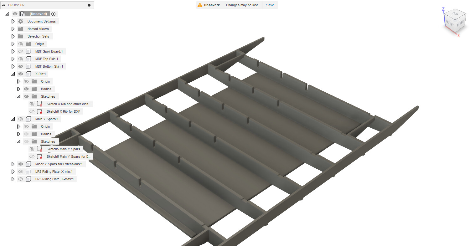
This results in the X ribs and Y spars appearing like this: (I made the top surfaces invisible, and by turns the Y spars, and the X ribs invisible for screenshot.) The DXF versions of the sketches look like the extruded parts.
I can fix the drawings so that they are as (I assume) they were intended easily enough, but I thought that you should know.
Possible refinement: The bottom cover seems to want the extra clamp surface as well, which I believe is unnecessary. At the very least, my plan is to build with the bottom box cover flush with the end X ribs.
Edit: zip file stuff may be a Windows 11 thing. I updated my laptop since it’s not a critical system to me, and I figured that I could see what it breaks. Long filenames in .zip files may possibly be one… but I don’t know.