Perhaps both? A vase mode, 2 perimeters, 3 perimeters, see if anything exaggerates etc? Could cancel the print halfway through once it shows up and look at the walls from the top?
3 Likes
That’s a good plan.
3 Likes
No, the belt attachment point. If there’s any angle from the pullies to the attachment point on the effector, it’ll cause issues. Ours is off, so it’s not a perfect 90deg angle.
by “ours” I mean the railcore.
4 Likes
This is roughly the behavior that we saw originally.
I had waves on X and Y, although X was more pronounced than Y.
Turning it 45 degrees, the B Motor (the one in the video above) side had waves, while the A motor sides did not. I don’t about the relationship of the wave distance on flat sides vs diagonal sides though, as I wasn’t paying attention to that. I only measured on the diagonal sides.
The fact that we were able to isolate it to one motor is what gives me hope that it will get corrected when the motor is replaced, but while I waited for them to arrive, I just wanted to go through everything and make sure that I was confident that everything else was right.
That’s pretty much all my test prints have been
I only did one before I left, but this is the square turned 45 degrees, with the new 20T pulleys
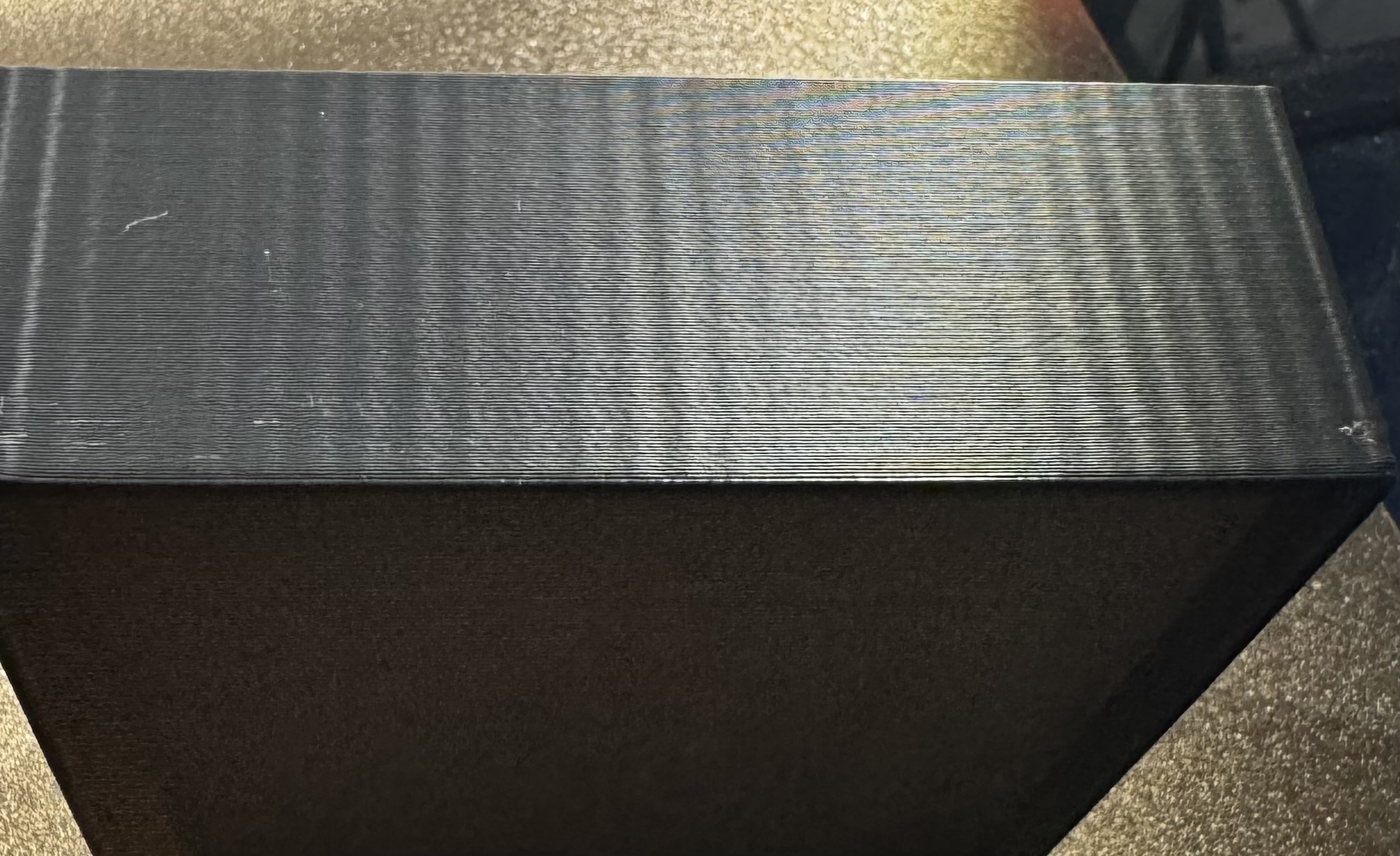
While you can see them, in this case, I don’t think you could feel them as much after I changed everything
If I remember correctly, I think the spacing was ~2.6mm now
2 Likes
Wait. You don’t have a box of extra stepper motors!? Weird… 
1 Like
Well… now I will lol
3 Likes
I just made and printed this. You can see my worst print in the pictures. I am only seeing a very tiny ripple on the X axis. I swear, I used to have a pretty nasty ripple on one axis. I was pretty sure mine was bearing related, so maybe they have worn in.
https://www.printables.com/model/918498-test-print
Taking a real critical look, my front X face is the worst and it is fine on the back X face, so maybe my frame has a slight flare back to front.
1 Like
Is it possible the tooth shape is not right on one of the idlers or pulleys?
1 Like
5 Likes
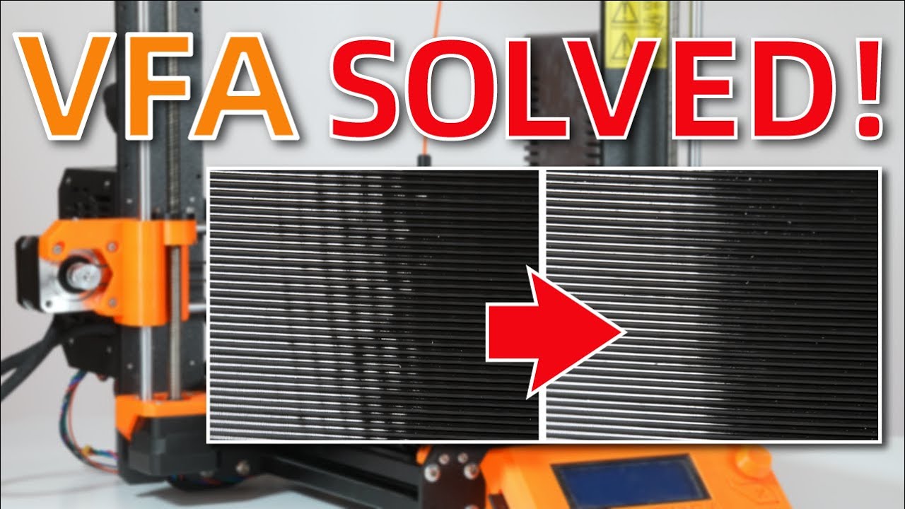
It’s not the only source of ripple, but it’s a source of ripple.
and just to make you feel better, the new prusa corexy has ripple.
1 Like
Dang, good find Barry. I feel like I had seen that somewhere but did not pay enough attention.
They made a better stepper, but cite speed as a factor. That adds up. Mike your larger pulley will spin slower for the same speed, larger ripple distance. Wonder if interpolate would change that at all.
1 Like
I think barry is right, thi is likely coming from the motors.
One other possible cause I was thinking about before was the “chordal action effect”. when you have a chain or a belt and small diameter sprockets, there is a slight variation of tention during rotation.
The smaller the sprocket, the more pronounced the effect will be.
it’s better described here: 2.2.1 Chordal Action
But yeah, motor resonnance is the most likely culprit.
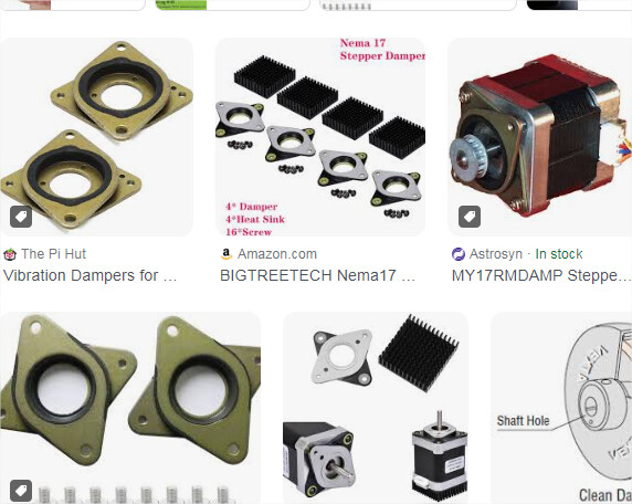
In which case you can always experiment with different microsteppings, different motor drivers and possibly some mechanical motor dampers. I never tried using these but always wondered if they made any difference. It’s relatively cheap so that might be an interesting experient to do.
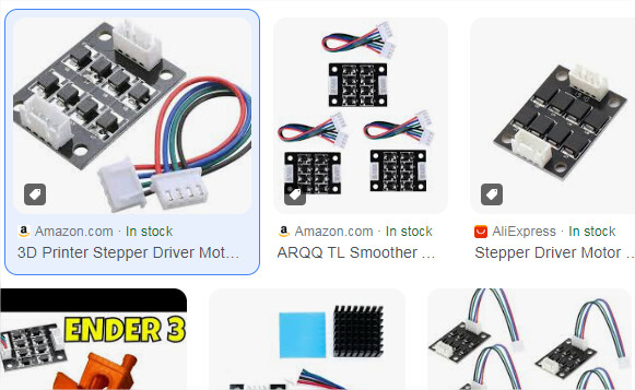
There is also the electronic equivalent with these little boards (here again I havent’ tried but always wondered):
Also an easy fix could be to implement input shaping. Not sure if you’ve already considered it, I’m a bit lazy to go through the whole thread to check again lol.
1 Like
Yes, input shaping doesn’t help. This signature is different than the resonance that’s present doing the input shaper test with curves on the faces. These lines remain vertical even when the test has corners that change shape on the face.
So I’m back home today. I replaced the motors and pulleys on the XY with the new motors, and back down to 16T pulleys…
And still the same.
Except the wave is more visible now on both belts than it was at some point. that might have been when I had the belts tighter though…not sure.
On the B belt, it’s definitely a pattern you can feel, not just see.
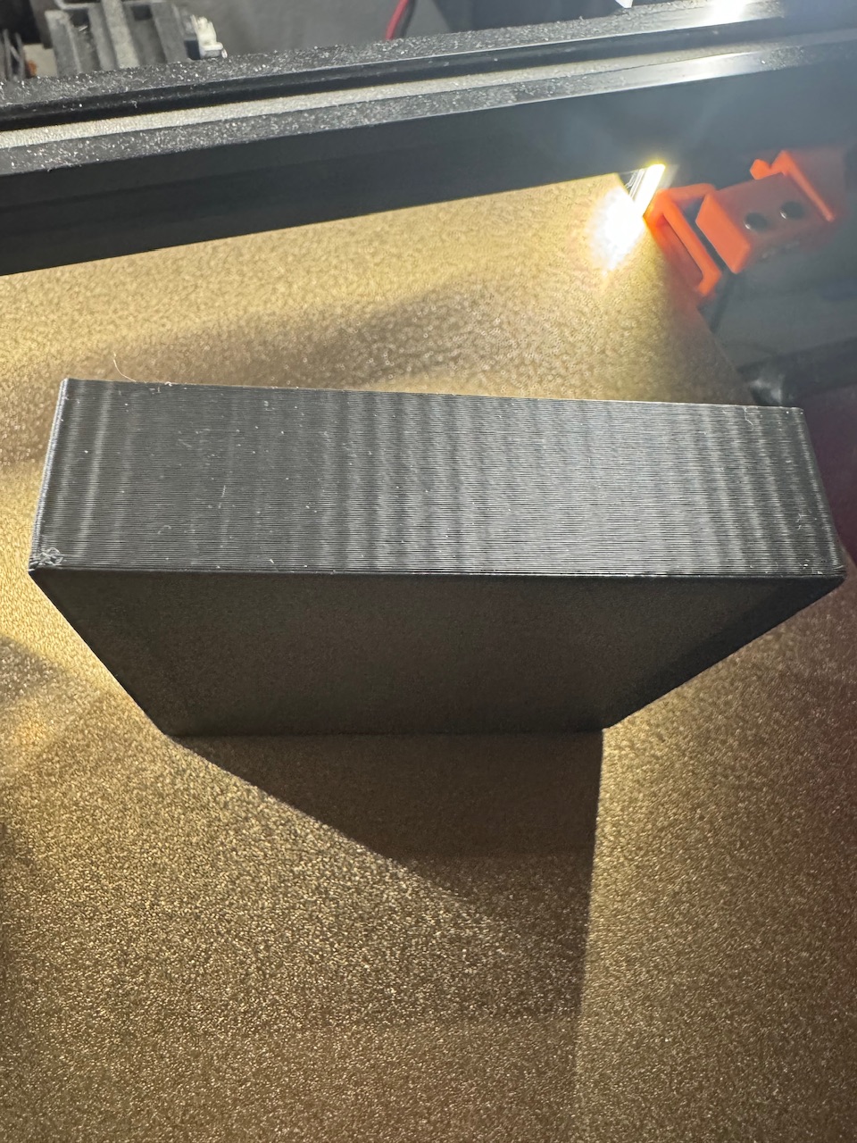
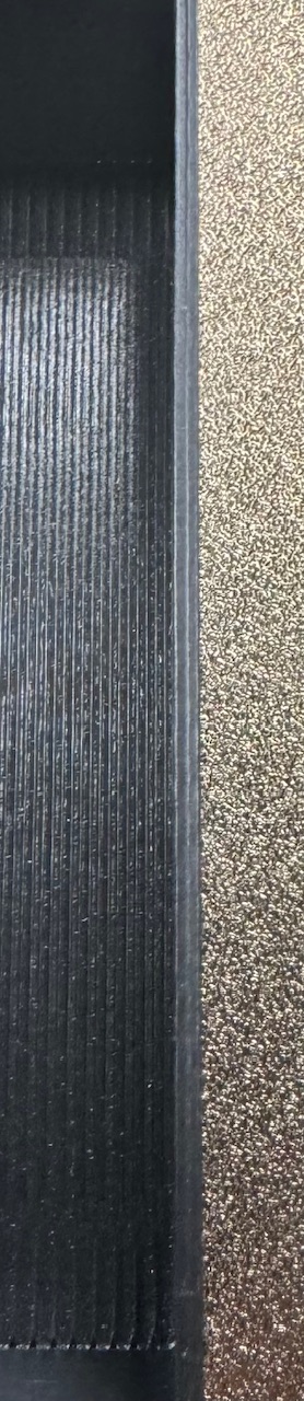
1 Like
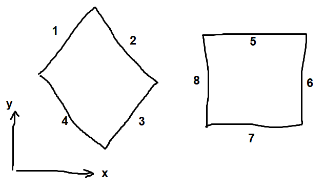
So just to be clear, the “B belt” is the one that moves when printing sides 1 and 3?
The way I think of it, one belt (driven by the back left motor) is shaped like a “p” while the other belt (driven by the back right motor) is shaped like a “q”. If the “p” belt is fixed (motor held in place) and the “q” belt moves, then it travels parallel to 2 or 4. If the “q” belt is fixed and the “p” belt moves, then it travels parallel to 1 or 3.
Also I am wondering, is what is the wave spacing on sides 1, 2, 3, 4, and it it the same or different from 5, 6, 7, 8? And are some sides worse than others?
1 Like
Yes
1 seems worse than 3. 1 and 3 are both worse than 2 and 4.
Previously, in the prints that started all of this (the scoop), 2 and 4 didn’t show it at all
3 Likes
This is super puzzling.
Okay, what about this?
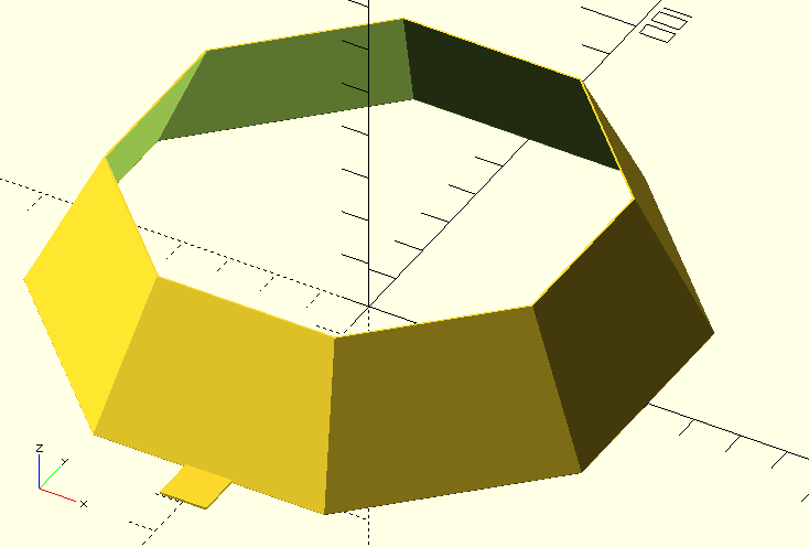
slant_walls.zip (1.3 KB)
I think there is pretty strong evidence that the ripples are tied to A and B (and not X or Y) but this should be conclusive. Or if there is a mixture of effects from X and Y and A and B, then the slanted walls should show diagonal ripples (maybe a mixture of diagonal ripples) that indicate the individual contributions.
It is also possible that for example the belt tension of belt A changes periodically with motion of belt B or vice versa, and this causes 1 to be worse than 3.
The tab on the front is just to indicate the orientation, or else it’s going to get super confusing as to which side is which.
2 Likes
Make sure to print it with thick enough walls. For some reason I was seeing funky stuff on thin walls, it all went away when I had enough thickness, I do 2-3 walls and typically I add a bit of infill just to be sure no thin wall slicer math is going on.
1 Like
Hmm, I hadn’t thought about that.
The original should fit an extrusion width of 0.4 mm.
Here is one with 1.2 mm thickness:
slant_walls_1.2.zip (1.3 KB)
1 Like
If you make it solid the slicer can pick and any printer can use it.
For example 3 walls 0% infill, or vase mode, etc.
1 Like