So if this were true, it seems it would only be x or y. That wave is very uniform. Also i would expect it too only be in spots.
I think @brenavich980 might be on to something…
it looks like a couple of the idlers are sitting 1mm lower than the others
the CAD shows 123.25 mm from the top of the frame to the top of the pulleys/idlers.
I’m measuring 123mm to the top of the pulleys. 0.25mm high.
Many of the idlers are 123.5mm. 0.25mm low.
Some of the idlers are at 124.5mm…an additional 1mm lower…
I have not worked out why yet…but will try to get them inline and see if that helps.
2 Likes
It should be just over 9mm belt and 11mm idler. The offset should not be it. If they are angled though that would be bad.
1 Like
My belt is dead on 10mm.
I’ll at least get them back in line anyway and run the print first. It will either fix it, or rule it out.
I was able to pull the front left side back in line just by loosening the screws on the panel and pulling it up.
Looks like the amount of play in the M3s going into the rail just allowed it to drop and get out of alignment.
I’m about to pull apart the back left side and check those spacers. I might need to reprint them.
1 Like
On the V0, the idlers and pulleys were all square to the frame but the difference in elevations between them made the belt enter the idler at an angle.
Very different machine though. The pattern on @Michael_Melancon prints is exactly what my prints were showing at it only seems to be in one of the belt runs. Hopefully it’s something simple.
I tried to re-align some things yesterday and it didn’t solve anything, but I found what looks like a few discrepancies in measurements.
So I think I’m going to go back through and re-measure and make sure everything is square and right compared to the CAD.
It looks like it’s possible that installing the side panels caused some things to shift when I remove the corner brackets, and maybe too much faith was put into the ability for those t-nuts to align properly.
Things don’t look that far off, but I would feel better just going through it again.
I looked back last night at some earlier things I printed, and the waves were not present then. So something must have happened during the course of the disassembly and reassembly fixing the other issues, or when installing the panels, that caused something to get misaligned.
I’m going to try to go back through everything related to making sure the outer frame is still square, and everything in the XY assembly is still square and matching offsets where everything is supposed to be, and see if there is anything bad in there.
Then I’ll re-asses.
It may be bit though because I have some work stuff coming up, and I’m not 100% sure I’ll be able to get through it all before I get tied up.
I’m going to try to do it this weekend, but we’ll see.
2 Likes
Your belts cross smooth side to smooth side, right?
1 Like
you mean the flip in the back?
It seems to work fine. slides on the PTFE without issue as far as I can tell
2 Likes
Ok something is odd here. In your build post, those waves are not there!
I just went through and saw your first parts, no waves. At this point, maybe start with a clean printer config and see what happens!
1 Like
yep, I went back and looked at a few things. I’m going to go ahead and make the disconnects for my motors so I can properly take apart the XY.
Then check the frame, then reassemble checking all of the offsets all over and see what it looks like then.
I’ll probably go ahead and reprint the spacers and stuff too just in case they got worn in in a weird way or something
3 Likes
Well…that may not be 100% true…I am seeing some artifacts on some early prints… You can see on that front right cube.
In the beginning I think I brushed it off because my I assumed I needed to tune input shaper, but later realized it was something different.
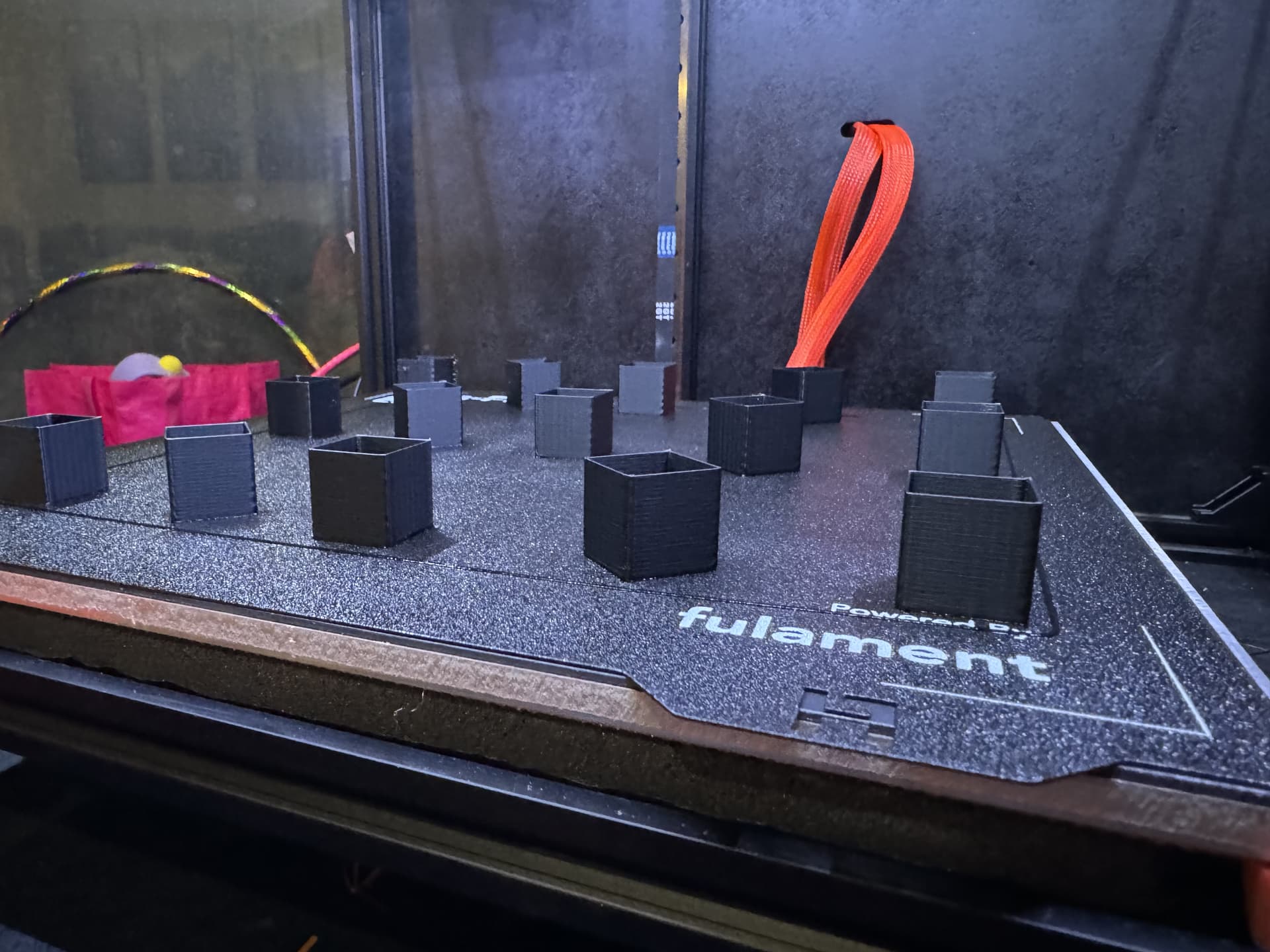
This was a test print I was doing to check on those funky corners. Those corners is what actually started this entire mess of trying to work out issues…
I’m not 100% that one is solved either…so there may be a follow-up thread after the waves are solved ![]()
1 Like
Hoping for the best for ya!
2 Likes
Just double checking the obvious here, you have the correct nozzle size defined and the print width is 110-120% of the nozzle diameter? I did get funky stuff when I had it set wrong when I switched to the 0.6.
1 Like
yep. 0.6 nozzle, 0.66 print width
Edit: ugh….got no idea how or when, but now my profile has 0.63 for external perimeter instead of 0.66.
I need to go do some test prints….
1 Like
no, we can’t really feel them, just see them in the light. All my belts, idlers, and gears are the spendy genuine gates brand. A bunch of us went through a lot of crap trying to track it down. It even has a name, “the ripple”. I’m using superlube grease in the bearings.
Can you upload your klipper config? I’m not sure what I would look for, but something might jump out.
2 Likes
ok, perimeters set back to 0.66, tried a bunch of stuff…still the same
2 Likes
I’ve seen it show up on prusa’s big printer too.
forgot we even have an emoji for it on the discord. ![]()

2 Likes