Calibrating, cutting too small

Alright, I just setup my first mpcnc and things went fairly smoothly through the crown test. The first thing I wanted to build is a simple little box, I quickly noticed that while it seems square it is a bit too small all around. The length that is supposed to be 110mm is 106.65mm and the length that is supposed to be 45mm is 43.13mm

What are the steps too troubleshoot? I did briefly try to tighten the belts but very quickly it started to chatter and skip.

Thanks in advance for any help I will post some photos from my phone in the first comment.

Your particular issue does not match with the typical issues we see in sizing. If it:

  • …was substantially larger, then it is likely a pulley issue.
  • …was the same X and Y, it is often an authoring issue with not defining the bit size correctly
  • …was not square, then it was likely lost steps
  • …larger than expect, then it is likely a deflection issue.

I suggest:

  • Put your pen back on and draw some squares and measure them.
  • Manipulate the core by hand to see if there is any play.
  • Examine the g-code to see what it should be cutting. Note it will cut 1/2 a bit with out from the line you defined. If you have trouble decoding the g-code file, upload it to a post, and someone here will gladly take a look.
  • Measure your bit width and compare it to the width you defined in CAM.
  • Listen for lost steps during the cutting. Lost steps will make a buzzing or grinding sound.
1 Like

Okay, first off…

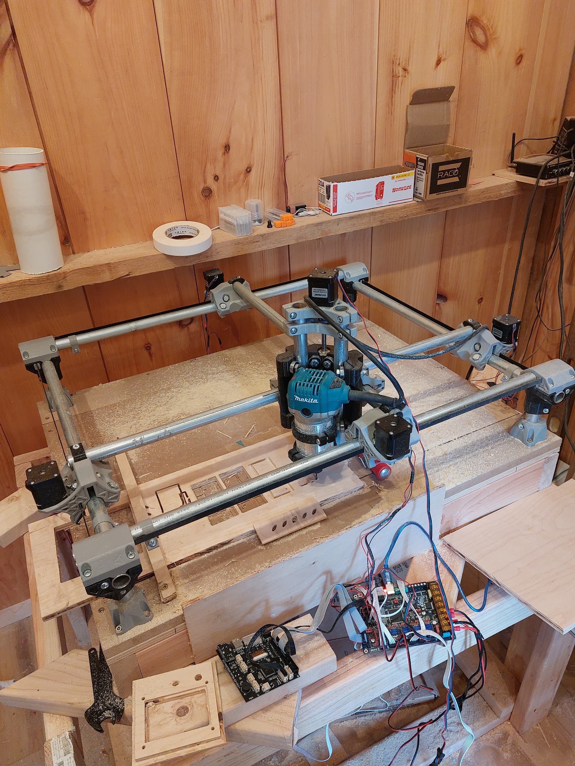
Make sure the belts are reasonably tight and that there is no wiggle in the machine core.

Check your CAM. The bit size could be wrong.

My first few parts were off, holes were too small, parts were too big. So things that should have fit together did not.

Cut some parts in foam, or something soft and cheap.

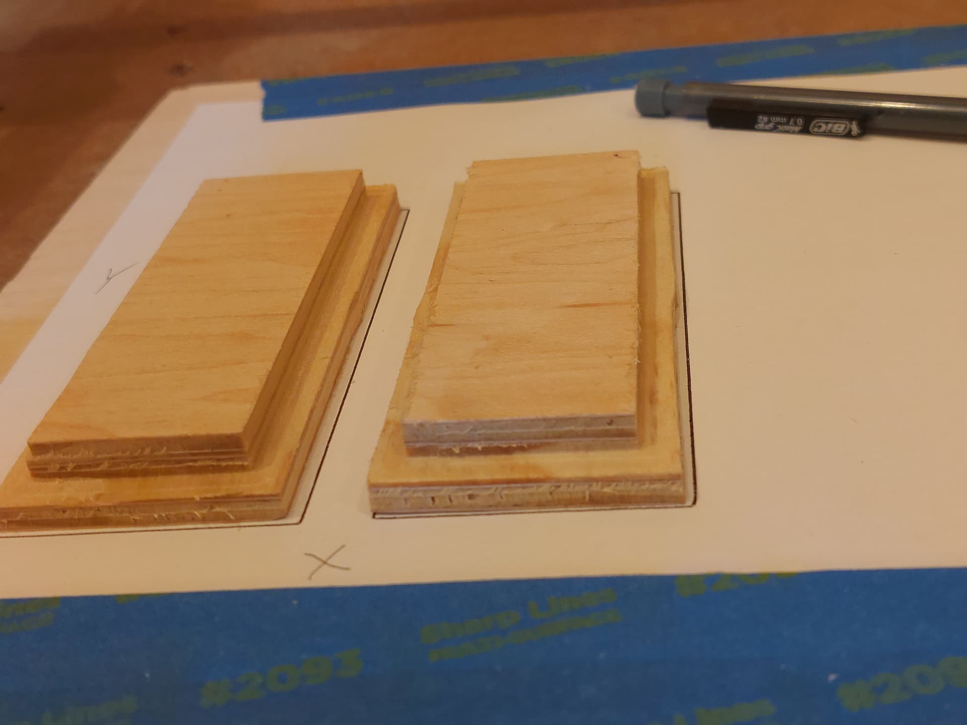
Cut some rectangles (with rounded corners) and holes, and try to fit them together. Try these in 2 different sizes, say 50mm and 100mm.

If you have your cutting diameter too small, the parts will be undersized, and the holes will be oversized, and you will have a sloppy fit.

If you have your cutting diameter too large, the parts will be oversized, and the holes will be undersized, and they won’t fit at all.

Adjust the cutting diameter until you get things to fit tightly, but actually fit.

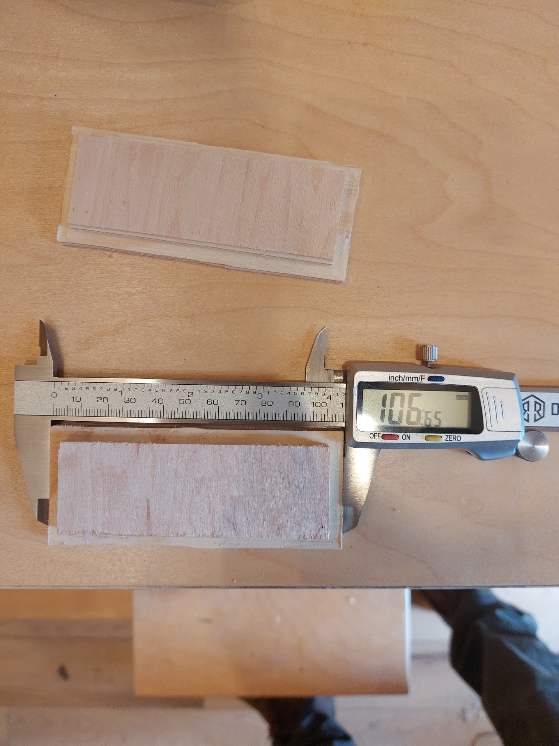
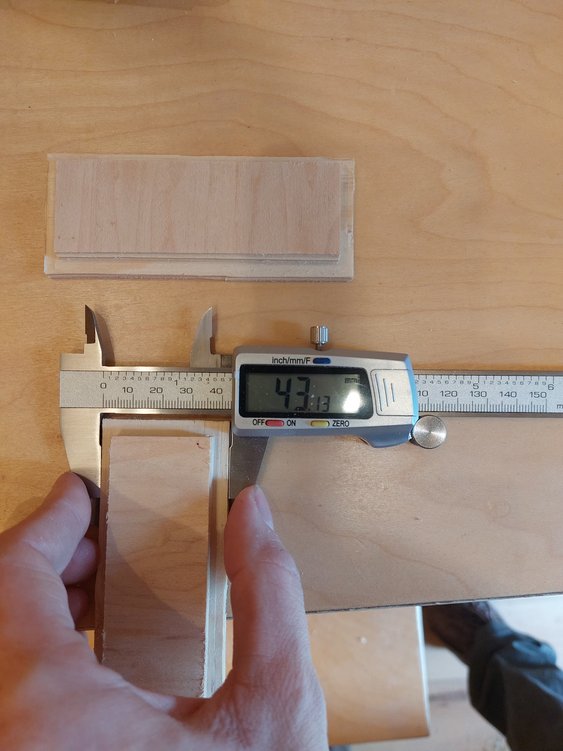
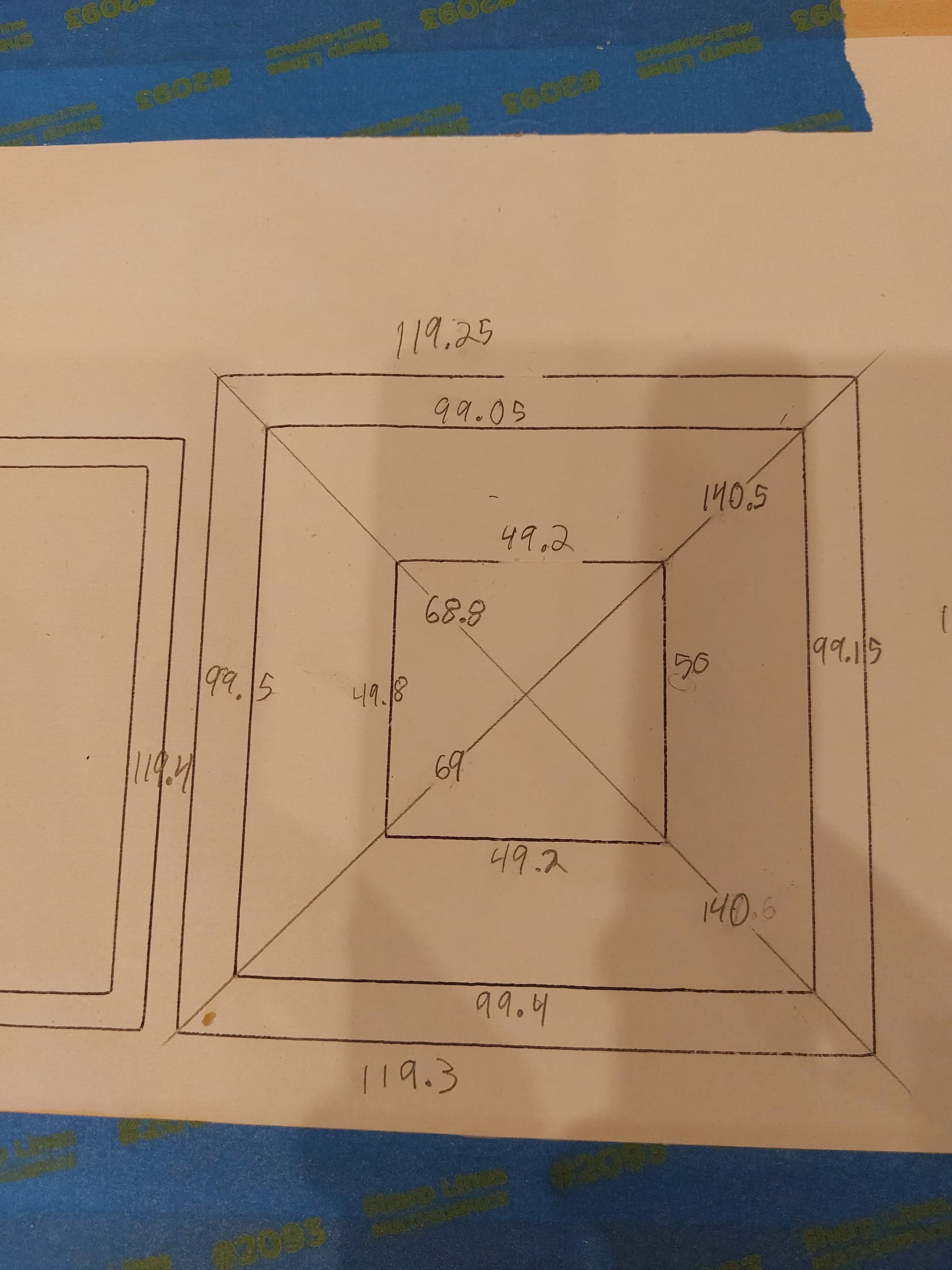
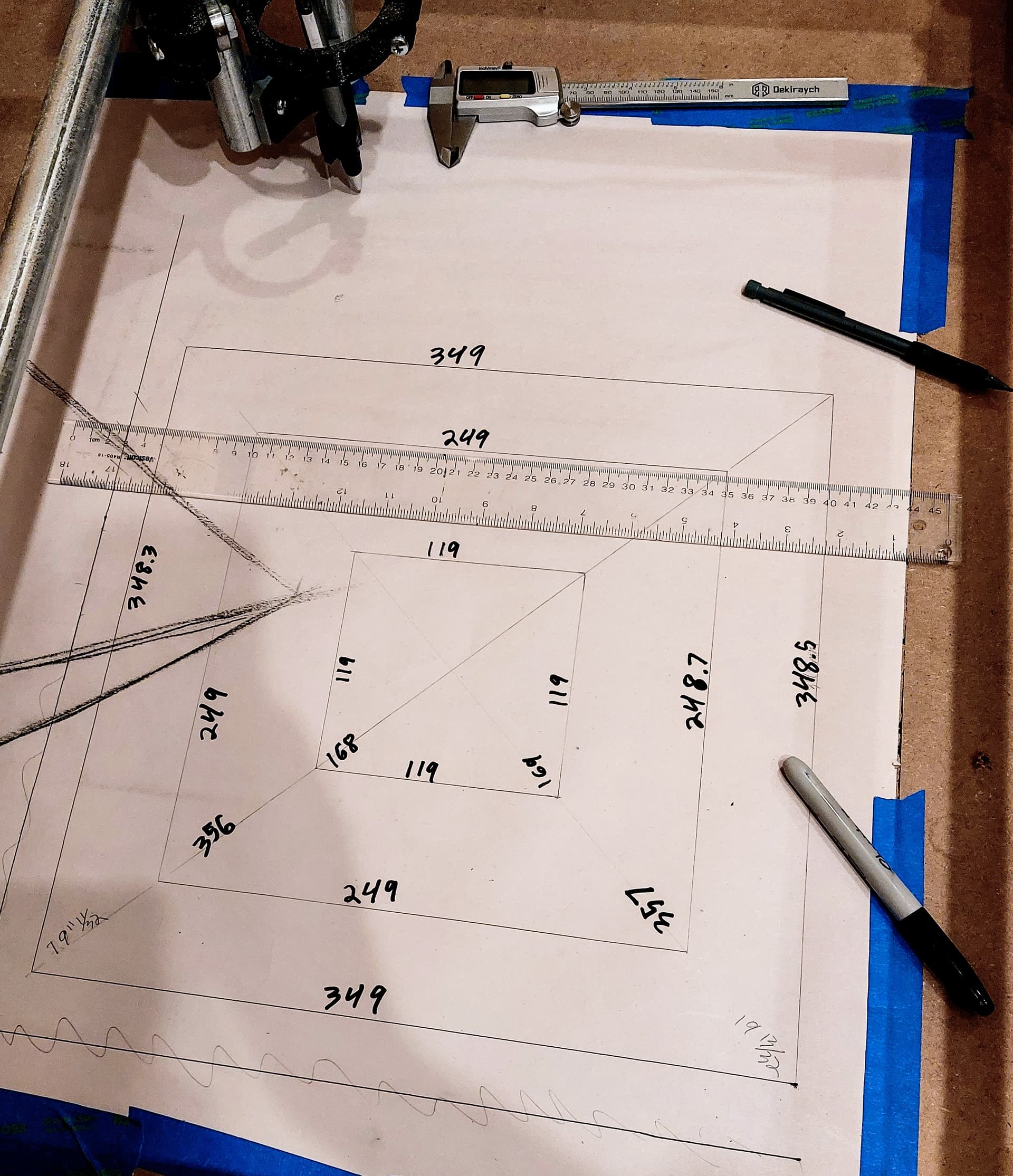
Now that you have a cutting diameter that matches, measure the size of your parts (and slots) and compare them. Because bow both are the same size, any error between the parts and the CAD is the machine movent.

Label the parts for X and Y axes, so you know which size is off by how much.

When I was done, I found that the 100 steps/mm was right.

1 Like

Also verify how you have defined the cut in your CAM program. Are you cutting on the inner edge of the line, the outer edge, or on the centre of the line?

1 Like

Oops looks like I was in a hurry and made a typo, the longside Y was supposed to be 108, which makes it closer to being off in even amounts.

I did put the pen back on and drew some squares, I also had it draw the same piece to see if it was similar. I got a perfect 45mm on the X and slightly closer Y at 107.3

This is the result of the square test I ran, I expect there could be a bit of wiggle room with my measuring but should be pretty close.

Check cam for corect inside the line outside the line or on the line that will make a 1/2 the diameter or the diameter of the mill you are using. If not also measure the mill i got some froom amazon the were not as stated😒

For the pen test using Estelcam I did on the line using the “engraving” function. which while much better is still not quite right.
I am using some cheap bits from amazon, which are a bit smaller than a 1/8" bit should be, they measured 3.13mm instead 3.175mm however I adjusted the diameter in Estelcam… and yes I checked that the cut was on the right side of the line for those.

This is a puzzle. Did you examine the core for movement (though I would expect different numbers from a loose core)? If you did not examine the g-code file for the pen work, I’d like to take a look just to make sure the CAM is being calculated correctly. You can upload the g-code file to a post.

Can you run a couple of pen square tests using most of your spoilboard? The larger format squares will be more accurate, and I’d like to see if the under sizing grows with a larger size square.

Looks like backlash. Have you checked the grub screws on the pulleys? I would be surprised if it was affecting them all about the same though.

1 Like

I will try some larger squares tonight.

Since I am a new user it won’t let me upload a file :confused:
Here are is the code for the first box:

;Project squares
;Created by Estlcam version 11 build 11.245
;Machining time about 00:02:39 hours

G90
M03 S24000
G00 Z3.0000 F480

;No. 1: Engraving 1
G00 X0.0000 Y0.0000 F2100
G00 Z0.5000 F480
G01 Z0.0000 F180 S24000
G01 Y0.8660 Z-0.2500 F180
G01 Y0.0000 Z-0.5000 F180
G01 Y120.0000 F900
G01 X120.0000 F900
G01 Y0.0000 F900
G01 X0.0000 F900
G00 Z3.0000 F480

I put locktight on all the grub screws but double checked anyway… Nothings loose.

The period between being a new user and being able to upload a file is very short. What extension was on the g-code file? The forum software only allows certain file types to be uploaded, but .gcode is one of them. If the file type was not .gcode, changing it to .txt or .gcode should allow you to upload your files.

As for your g-code, it is correct for an engrave, so I don’t need to see any additional g-code files. Your measurements should be taken from the center of the ink lines. It is hard to tell from a picture, but it looks like your lines may have a width of 1mm or more. That can make it hard to get an accurate measurement when looking at discrepancies around 0.5mm. Also, what pen holder are you using? There can be some flex in some of the holders, though typically that flex in the direction of travel, not sideways to the travel.

I would like to see you do a large square and measure the result. I want to see if the issue scales in any way, or if you are consistently too small by about 0.5mm no matter what the size. Also, a large square will allow you measure the diagonals accurately to see if this might be a squareness issue. If your machine is out of square, then the lines will be closer together than specified.

I am puzzled. A lack of squareness is the only thing I can think of that comes close to matching your symptoms. Your measurements of the diagonals of your small squares do indicate your machine may be a bit out of square, but I don’t think the amount is enough to account for the smallness of the measurements between the sides of the squares.

Alright I did some larger squares. Per my luck the pen gave out halfway through but I was still able to measure. Using a clear ruler was as exact as I could measure at that size although there is certainly more margin for error. When I measured the smallest square which same size as the largest on my previous test with calipers I got 119.3 which is the same as I got before.

For the diagonals it does seem to be slightly off, I had to switch to an inches tape measure for the largest square which as exact as I could get it I seem to be off 1/16" about 1.6mm.

UGH I have half a mind to strip it down and rebuild.

No, you don’t need to strip it down and rebuild it. You just need to 1) move the endstops to physically compensate and/or 2) use an M666 to compensate in the firmware. There is some information on making the adjustments on this page. Personally, I’d start by adjusting the endstop stop blocks until you are a lot less than 1.8mm off, then (if necessary), use M666 for the final, small adjustments.

I’m assuming you are homing to square the machine before you are drawing the squares.

Ok I will start playing with the endstops to get it as square as possible. Do you think that will take care of the size issue too?

I physically homed the machine though not for every test, just when I felt I bumped something…

I think it is a good habit to zero the machine every time you start a job, because when the steppers are not powered it is easy for the axes to move. At least that’s my method.

1 Like