You need to square the machine any time the steppers are not engaged. As long as the steppers are engaged (and you are not losing steps somewhere), the machine will remain square. Note that, to a certain extent, the machine will seek an angle when the steppers are not engaged. Part of the build instructions has you adjust things so that the natural state when the steppers are not engaged is approximately square.
Do you think that will take care of the size issue too?
Squaring the machine is a needed step in your machine setup, but I don’t think it is the root cause of your issues. First, you have to be pretty far out of square to generate a 1mm difference. With 350mm sides, your machine would have to be off by about 4 degrees to generate a 1mm difference, and that would have your diagonals off by far more than your measurement. Your size issue is weird. You seem to be off by the same amount no matter the size of the square, the amount is always smaller, and seems to apply to apply (to some extent) to both the X and the Y dimensions. For most causes of a size issue (including out of square), I would expect the difference to be a percentage of the size of side length of the square. A CAM issue is the most likely cause of being out the same amount at different sizes, but we verified the g-code above. Maybe @vicious1 has an idea of the root cause.
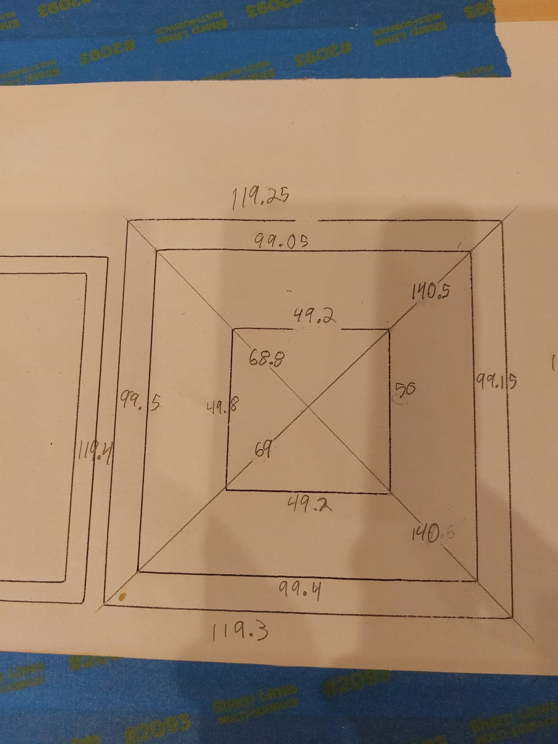
You can easily rule in/out squareness as the root cause by measuring the line lengths, not the distance between the sides. If the actual lines are too short, then squareness is not the underlying issue.
I think either you have slop in your mount, or a sloppy pen (ball points can move almost 2mm in the tip) or you are pressing too hard.
For super accurate drawings use a fine point gel pen (I have a 0.3mm), from there it should only be pressing 0.2mm or so. (fancy pen Amazon.com)
Your error is very consistent, and does not scale so I am assuming it is pen/mount related.
You can also just mark out the corners if you want to go much bigger. Jamie has a gcode generator for that. (I really need to link that in the docs more) G-Code Test Pattern Generator
I like to think through all the things that go into linear distance:
The belts are 2mm between teeth. They have fiberglass in the rubber so they don’t stretch much until they are pulled very hard. This is one place where there is a little slop, but it is usually bigger results, not smaller. And it is usually proportional. It should be the last thing you adjust for because the rest of the system isn’t sloppy.
The pulleys on the motor shafts have exactly 16 teeth. They don’t have 16.01.
The motors have exactly enough magnets to have 200 whole steps per rotation. They also can’t have fractional magnets.
The stepper motor drivers count microsteps effectively perfectly. Unless there is strong electrical interference, they never miscount.
The firmware that sends microsteps to the stepper drivers is counting very accurately too. It won’t miss a step unless there is very strong emi and the results would be pretty random.
The firmware computes how many steps to send based on the steps_per_unit calibration parameter. If that is wrong, you would get a proportional error. The default firmware is based on theoretical values and assumes the belt is 2.0mm per tooth. They would be 100,100 for X,Y. You can check by sending M92 and seeing the response, or the values are in the config file. I don’t think this is your issue either.
That is the linear movement system from end to end. It looks to me like you are missing 1mm on every dimension, at every length. That screams backlash to me. What I mean by that is the first mm of movement is swallowed by some slack somewhere and then the next 349mm are fine. When it changes directions, 1mm is swallowed again and it goes 349mm the other way. Where could the backlash be?
This is a case where being in the room can help, so it is hard for us to figure it out. Something is slipping 1mm in X and Y. If you apply a small pressure on the pen (drawing has almost no load, so only a small pressure should do it), what moves?
As Ryan suggested, the pen mount is a common suspect. An ideal mount is squishy in Z and rigid in X and Y. The right amount of pen pressure means very little load on the pen and that significantly reduces the XY flex. You can go back to the router and use something that offers no resistance (like the purple HD foam from the home depot).
Another issue could be a crack in a part. Are the parts rigid? We are talking about a crack that lets it move 1mm in X or Y. The consistency between axis makes me suspicious of this conclusion. I would assume a crack would affect one axis only or one axis more than the other.
Are the bearings touching the tubing everywhere? If they click when the movement changes direction, that might cause the backlash. If that first mm is swallowed by the trucks rotating to touch another bearing, that would explain it.
Are the belts tight? I hesitate to suggest this because people so often over tighten them. But if the belt is loose, it might move 1mm before being tight and the machine would then travel precisely.
Are the feet, table, and work holding solid? Just somewhere else to look.
Ultimately, backlash should be easier for you to see and feel than most problems. I hope this will help you get a good mental model on the machine and be able to sense where the error is. You are definitely stronger than the machine and the machine will flex. That isn’t the issue. It is the first mm of backlash even when using a pen (no load).
There is also this test pattern generator that works with a pen and paper. It draws a ruler in one direction and then reverses. If it is perfect backlash, every mark after the first one will be the right distance and the two rulers will be 1mm off:
That and the squareness marks. Using this will eliminate your CAM as a source of error. If you said “draw next to the line with a 0.5mm bit”, you will also get a 1mm error.
Using these two tests we should be able to narrow down what to look for.