Might need a little gluestick with pei and petg. The glue acts as a release agent. They can bond really well sometimes.
1 Like
I just do a alcohol wipe before each print, every few months though I will need to do alcohol and a mr clean magic eraser…then everything sticks. I think that is only needed when I mess up and and have greezy pizza hands or something though.
1 Like
Thanks for suggestions guys.
I’m sure that this is not PEI. Not sure what the coating is, but I’m sure what it isn’t. I have a PEI coated plate on the way. This one is probably OK for PLA (I have some of that coming, too.)
I have found that as long as you’re reasonably careful with the first layer, the PETg and PEI don’t bond too badly, and I’ve seldom had real problems getting my prints off of the bed. For most things that I print, I like the durability of the PETg. It’s not quite as rigid as PLA, but also not as brittle. It can take a little more physical abuse for many household tasks. Plus most of the stuff that I buy is rated safe for food storage, so I have things like lids for the water jug I keep next to the coffee maker. GThe somewhat higher temperature resistance is also useful. It’s not quite able to make things withstand being on the dashboard of the car… but at least when it melts I can still get it off. I had one car with a pretty much permanent PLA smear on the dashboard from a phone holder. Don’t print those in black…
I will be putting the front on the printer today, and trying to print some PLA on the print bed that I have. I strongly suspect that it will go better, so long as I can remember what temperatures everything actually works at, lol. The firmware preheat is set for 196/62, so I guess I’ll start there.
1 Like
Lately I have been printing pla at 215/62
2 Likes
Oh, nd in the “weirdness I have no explanation for” category…
In the video above, you can see the G34 behaviour where it just uses the front/left 200mm or so of the print bed. After enabling babystepping, it started using the whole bed. I changed nothing else.
Anyway, since that’s the result I wanted, I’m not complaining, it was just weird.
I separated out the G28, G34 G29 into a separate Gcode file so that I can re-try printing for different bed adhesion strategies more quickly, but I hope to be able to keep that startup code.
Looks like my PLA spool has arrived, so off to try that.
1 Like
I use the different strategies depending on how big the part is that I’m printing.
Little trial and error… PLA doesn’t stick well either. Temp verified with my Ir thermometer, and it WILL stick… at 135°. O.o It seems that I can turn it back down after a while though.
Even then if this printer weren’t so smooth, the nozzle will pop it off.

1 Like
I have a coated glass bed from BTT(BIQU) that had a similar black coating, but it was like a screen almost. Didn’t stick for sh@t, so I just ended up slapping a PEI sheet right on top and that works pretty well.
1 Like
Probably what I’ll do if I don’t just trash it in frustration
1 Like
Been there!
On my Cr10s pro I’m using Tiny machine build plate. and works really well.for the Gridbot V2.5 I’m using [Filament Fula-flex](Fulament Fula-Flex 2.0 Spring Steel PEI Flex Bed for 3D Printing 310mm by 310mm and Magnetic Sticker with 3M Adhesive (Fits Cr10, Tevo Tornado, Nereus, Anet A8+, E12, and etc.) https://smile.amazon.com/dp/B07SH1S2C1/ref=cm_sw_r_cp_api_glt_fabc_XCXFDACDK6P8HXW65JKZ?psc=1) also works really well and that is also what I ordered for the new printer
For the I only need glue stick if I’m printing CF Nylon and ABS.
Well, I am trying a second print. 135° isn’t practical. It takes far too long to get to temperature, and the magnet sticker is only rated to 105°
So I just put a layer of blue tape on the sheet. Feels like giving up, but if it works…
the PLA print got some weird artefacts at the top. I’m running another PETg print on the blue tape at 90° temp. That should give me plenty of adhesion.
MP3DP “Repeat” serial number 000002


Awesome!
5 Likes
So some tuning, tweaking, and just getting stuff finished.
The wiring is still a mess because I keep trying to use the printer, so I can’t unplug stuff.
Currently the motors complain LOUDLY doing the G34 ABL, because I have the speeds cranked up too much. I wanted to see what it can do. 150mm/s seems to be more than it wants to. It will DO it, but it doesn’t LIKE it. I might actually be able to get away with this if I bump up motor amperage, but I’ll just dial back motion to 100mm/s until I stabilize things.
The wifi module can’t talk to the LCD. I think that this means that the wifi port is turned off in the TFT firmware. It works from the CNC mode firmware, but that’s not particularly helpful. I haven’t tried the wifi module.
Also on the TFT, whenever I go to touchscreen mode, it complains “Unknown command: M211”. I think because software endstops are disabled int he firmware, which is fine, and I can ignore it.
I wanted the wifi module in the TFT, mainly because I like that if it’s there, the TFT will display the IP address on boot.
I got the LEDs in the marquee working, so the in-printer illumination looks way better. I might add a couple more strips for added lighting, but I like having them light from the same direction you’re looking.
I still need to extend 2 endstop wires. The new crimpers are 1000% better than the old ones, I have only screwed up 2 crimps in total so far, and that was me trying something I shouldn’t have. Still not an enjoyable task, so I’ve been procrastinating.
Blue tape seems like a winner. Still needs higher temps than I like.
the PEI sheet that came … was 235mm. It’s going back and the (hopefully) correct one will probably be Monday. in the meantime, the blue tape will probably get my calibration prints out with good reliability.
Steathchop turns off at a certain speed, you can change it but I think it is somewhere at 75 and up…its in config.adv. That will make them very loud.
2 Likes
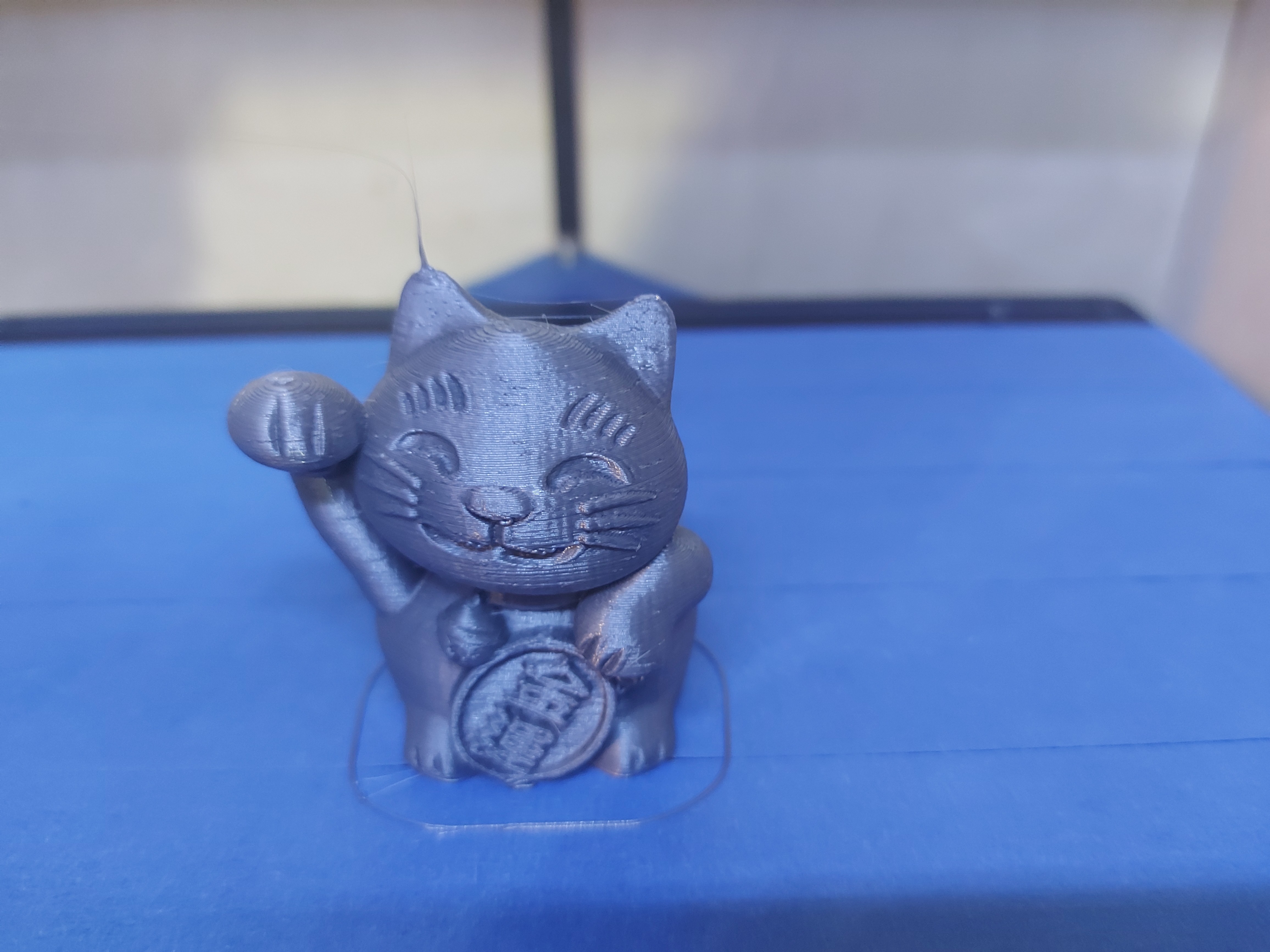
The current state of printing.
I have more of these little cat statues than I can shake a stick at now. Kind of like lots of people have benchys. (BTW, I’m pretty good at shaking sticks at things, so that’s lots.)
There is a ripple in X that I was chasing down, but I think it’s unavoidable…
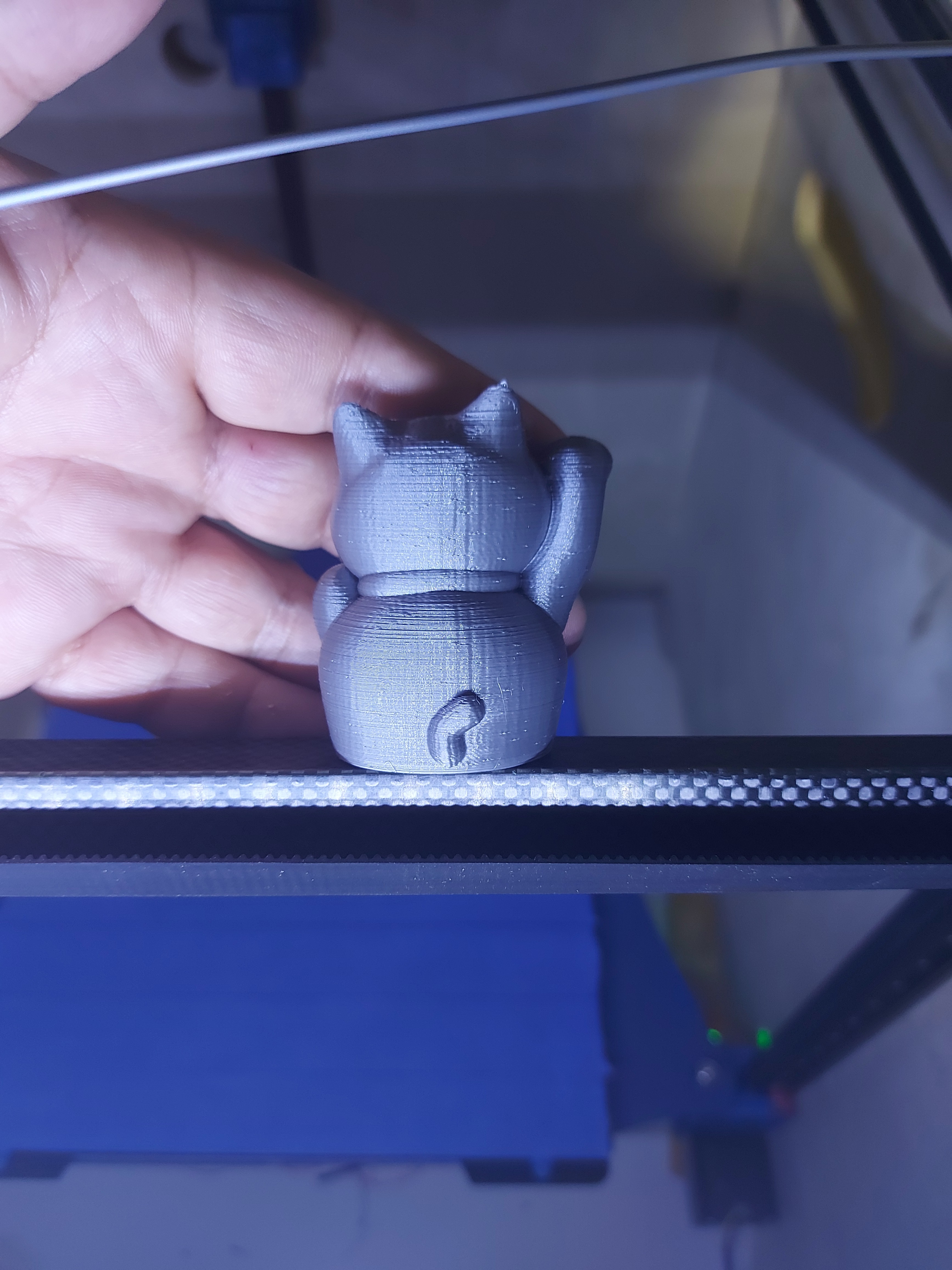
The pattern is the same width as the weave in the CF tube. Maybe one day I’ll buy some Aluminum square tube, but in the meantime, I’m probably stuck with this. It’s not that bad, I can’t feel it at all, and the light here was set up to increase the visibility of the ripple to a maximum. It goes across the whole width, remaining constant in the X axis. Y appears to be immune, but of course Y is on the linear rails. Obviously not all CF tube is going to be equal.
Print speed is fast. This was ~60mm in height, 6 layers/mm. Overhangs are very good, though not perfect (under the paws, you see some sag) Ringing is extremely faint, where I can find it at all.
Once I get the bed adhesion sorted, this will be great.
One thing that is probably related, I’ve never done much slicer tweaking with part cooling, because I’ve hardly ever had part cooling to tweak. The fan comes.on at layer 4 (disabled first 3 layers) and stays on. I thought I basically wanted it on for fast layers (like at the top with the ear points where it slows down) and bridging. I’d rather not have it on encouraging the parts to lift and curl, so I’ll have to figure out what logics turning it on, So I can get it to do what I want.
3 Likes
What’s the distance between lines on your ripple? I’m betting really close to 2mm.
I knpw where you’re going with that, and it’s close, but not exactly 2mm. It does exactly line up with the CF weave in the rod – or at least as exactly as I’m able to measure with this model. Also, it doesn’t happen in Y at all. I also tried lining it up with a piece of GT2 belt, and it drifts very slightly across. I’ll see about getting a picture of that relation. (It would make sense if the belt were stretched, but I checked relative to the belt across the X axis.)
I have seen similar ripples caused by using smooth idlers on the toothed side of GT2 belt, but I’m not doing that. 2 smooth idlers, 9 toothed ones in the BOM for this printer.
When you do more or less tension on the hub, how is that pattern effected? I do not have that at all.
Does that pattern change at different locations on the bed?
Heck, maybe try a straight wall across your bed to see if there is a larger pattern. Urethane wheels, and a lot of them, should significantly dampen any pattern that could possibly be there. I will have to try and introduce one on mine and see what happens. Your wires are not dragging on anything, spool is free?
You should be using a ptfe tube on your hemera anchored at the hemera and to the frame. So the filament does not influence it at all.
You can rotate the CF 1/4 turn as well.
1 Like
I am just thinking your tube, if it had a texture, should not have one all the way across, or equal on all sides. So a large wall the width of your build area would reveal that, and if it was perfect all the way across it absolutely has to be something else. Wheel with a bad bearing or flat spot, off center idler or bad bearing. And this also double checks that another model/slice does the same thing. Speaking to that, is it the exact same at different layer heights?
1 Like