I bet you can’t wait to get that tidied up. Wiring is the worst.
2 Likes
But first…
I thought that I knew which Z motor was which, but apparently, I did not.
I identified the Z endstops by the process of plugging in one at a time (right way around. The wiring harnesses that came with mine reversed 5V and S) and using M119 to query which were open.
Then, I tried homing it, and that was a heck of a mess. 2 stops trigger, and motors grind… OK. Sorted that out…

So now I have a machine that can find its way home… so long as it’s not TOO far away, the 400mm of Y travel kind of overwhelms the homing sequence.
I think fan0 is the part fan and fan1 is the hotend fan, simple enough to reverse if not, then that’s the wiring roughed in.
Still need the passthrough port, and I should extend the X2 motor since it’s running a funny path, but that depends on where the passthrough ends up.
Oh, and I’ll redesign the front panel to allow the fan to clear. I think that was an understandable oversight, since I didn’t have the hotend mount until I’d done almost everything else.
2 Likes
Negative and signal matter on these, but it sounds like you have two of the wires swapped, or plugged in upside down.
I am sure it can but you may or may not need more current for that. I never really tested full speed, just made some assumptions. I had a layer shift this morning so I might have the current too low in general.
On the bltouch port, but use the zmin for the white and black. Be very careful here you will destroy these with reverse current.
My bad I should have read it all.
Swap the build size in the firmware, and I use a rapid Z +200 on mine before doing the leveling. I also end my prints at Z max so start up homing is faster. There are a lot lot lot of options for this now. You can even hardcode the Z axis locations for faster autoleveling, but try my guess and check first to see if it gets it in less than 8 tries.
![]() My bad
My bad
2 Likes
I am really wondering how the leveling will do on a larger bed. I am guessing it will get within 0.03mm faster, but I could be thinking about it backwards.
Sorry, headed to Mom’s or I would go check the wire locations for you. Sucks the one time I want to take a trip you could really use me being able to poke around under the hood, sorry buddy. The hemera fan comes on after it hits 50C, the print fan is easy to test. You can turn it on with the screen (Marlin Mode I have not even attempted the TFT yet) and see which light comes on.
3 Likes
To be clear, I blame all oversights and mistakes firmly on myself. It’s not like I was just blindly following instructions.
Got the fans sorted out, I was correct there. Fan0 is the part fan and fan1 is the hotend fan. I turned on “fan 1” in Marlin mode and the fan0 light came on.The BLTouch is working, but I can’t zero the bed, because all of my locations are wrong. I’m going to have to change the locations in the firmware… but I don’t have the source repository (Board came flashed, and I’ve been using what it came with to get this far.)
No worries! I’ve managed not to destroy stuff (though one of the LED for my Z stops stopped working, but the endstop still works fine.) and don’t mind poking about myself. Just logging all of the little things that pop up here. If it sounds like I’m complaining, I am definitely not. I’m having fun.
I finished editing the front panel, just have to cut it out and paint it, and figure out something clever to do with the LED strips in there.
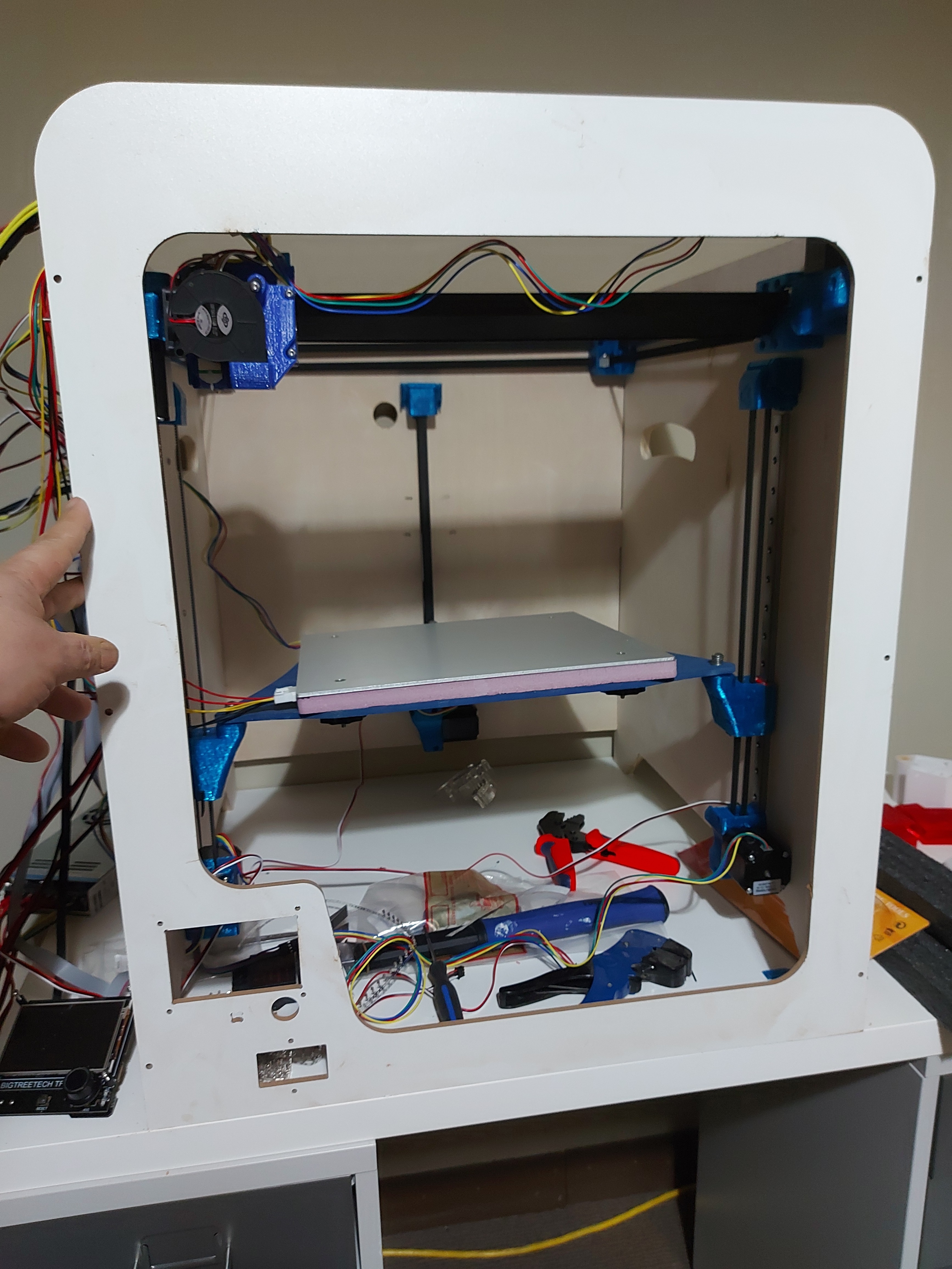
I bundled up the hotend wires, those were getting in the way, but I haven’t really made much of a harness out of the rest of them. Zip ties are amazing, they can make the most disastrous looking spaghetti wiring look like you were planning it all along.
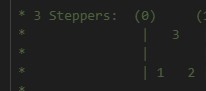
I suppose that I should have verified which motors go where. I set it up like so:
+-------------------- 2 --------------------+
|                     ^                     |
|                     |                     |
|                     |                     |
|                                           |
|                                           |
|                                           |
|                                           |
|                                           |
|                                           |
|                                           |
|                                           |
|                                           |
|                                           |
|                                           |
|                                           |
1<--                                     -->3
|                   front                   |
+-------------------------------------------+
I can re-arrange them if that’s not what the firmware thinks should be happening easily enough. I didn’t even think about the ABL until after I’d started wiring it up. I suppose that I would rather not have to do this by trial and error. There are 6 possible configurations for the 3 motors, it would be annoying to try to test them all.
The firmware reports an error when it starts up, I think because I have not done a mesh probe yet, and it’s trying to load the table. I assume that this will go away once I do a mesh probe and save it.
I have been using the TFT mode mostly for testing, which seems good. Actually, I’ve mostly been using the terminal mode to send Gcode directly. I haven’t actually tried connecting to the USB serial port. I do have the ESP01 flashed, but I haven’t tried using it yet, really, other than just connecting to the web interface.
Test fit to make sure it’ll clears the print head.
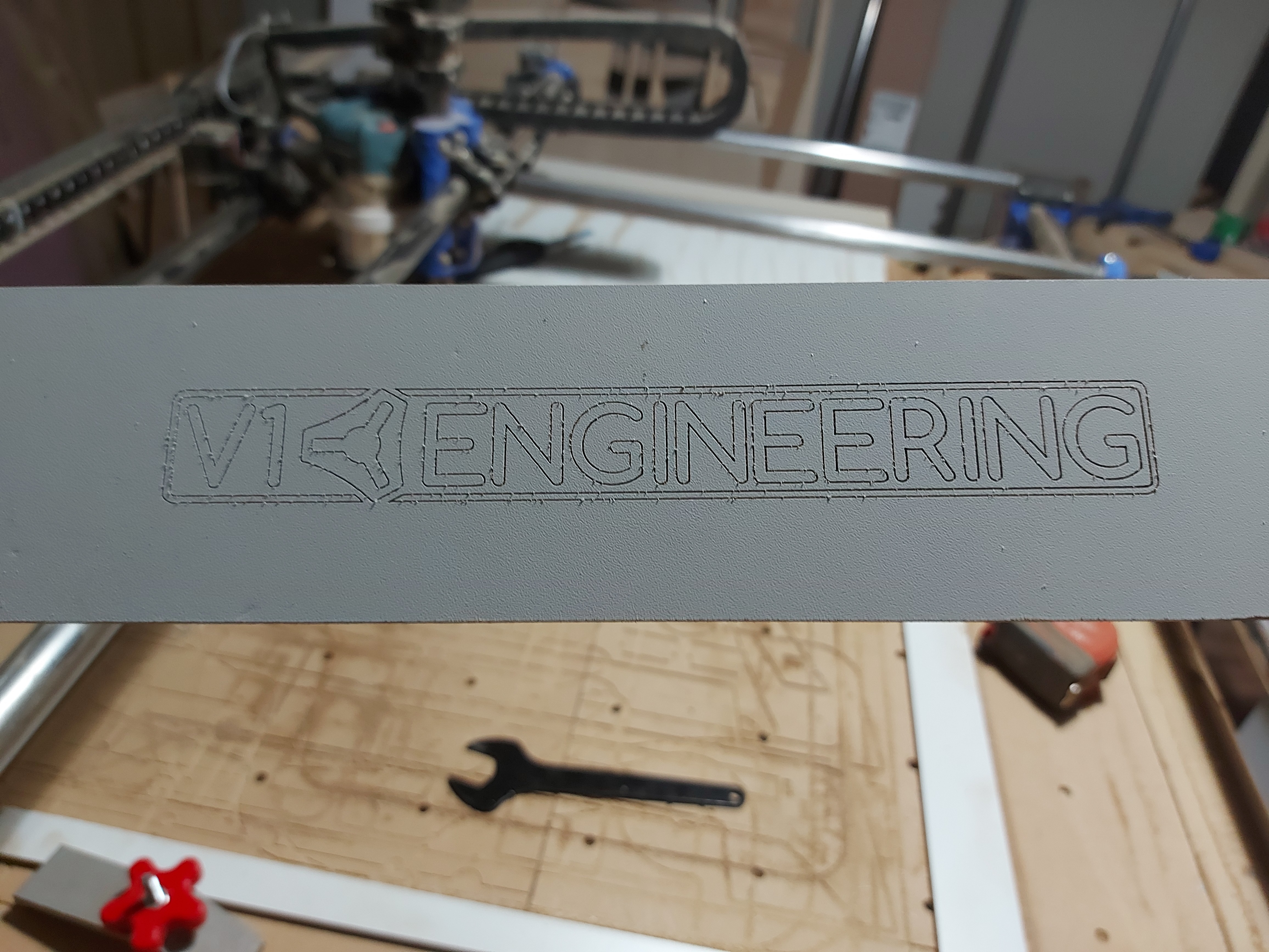
Engraving done. A little clean-up, then ready for paint.
Because this moves the marquee panel, I will move the light switch. Where I was thinking is no longer appropriate. It might need to go to the side. Not a big deal, just a change.
With the marquee now 50mm above the top of the side panels, I will reconsider a top panel. I’d still like one, as the bottom is quite a distance away, and I don’t want the frame to twist. I may have to change the implementation a bit though. Well I’ll worry about that after I get it printing.
Function test coming as soon as I can find Z=0
3 Likes
I really like the curves. My build has been postponed until after the move so I don’t have to store the old printer parts in a box, so I’m following your build vicariously.
2 Likes
Shoot, I thought I linked the firmware zip somewhere. I will see if I can upload something.
For sure, I appreciate the notes!
I am fairly certain left is 1, right is 2, back is three. You can look at any config.adv file and it has a little diagram just like you made. I can confirm when I get a little laptop time.
No mesh tables. That error might just be the TFT config missing something. I have my start gcode in the other thread.
1 Like
Uploading: Repeat and TFT.zip…
Okay this has the marlin build, and the TFT files.
For now any testing you do should be from the marlin side. You can use the TFT side but I am pretty sure it needs to be setup to work properly…it injects commands.
The stepper locations can be changed I just used the default
to have one less edit to keep track of.
1 Like
shoot, file is too big let me get it in google drive
I think this will work, did I share it right?
https://drive.google.com/file/d/14_kvvZW5kjY-KYtj5TRAilbNmu9CfSFe/view?usp=sharing
Most of what I’ve been doing with the TFT is terminal mode anyway, to send direct gcode commands. Mostly G0, with some G92
I’ll do some testing to get to placing the nozzle on the front left of the bed, so that I can set my stop offsets. It’s really no big deal to swap around the motor connections, so I’ll just make them match. The closer to stock firmware I can use, the better.
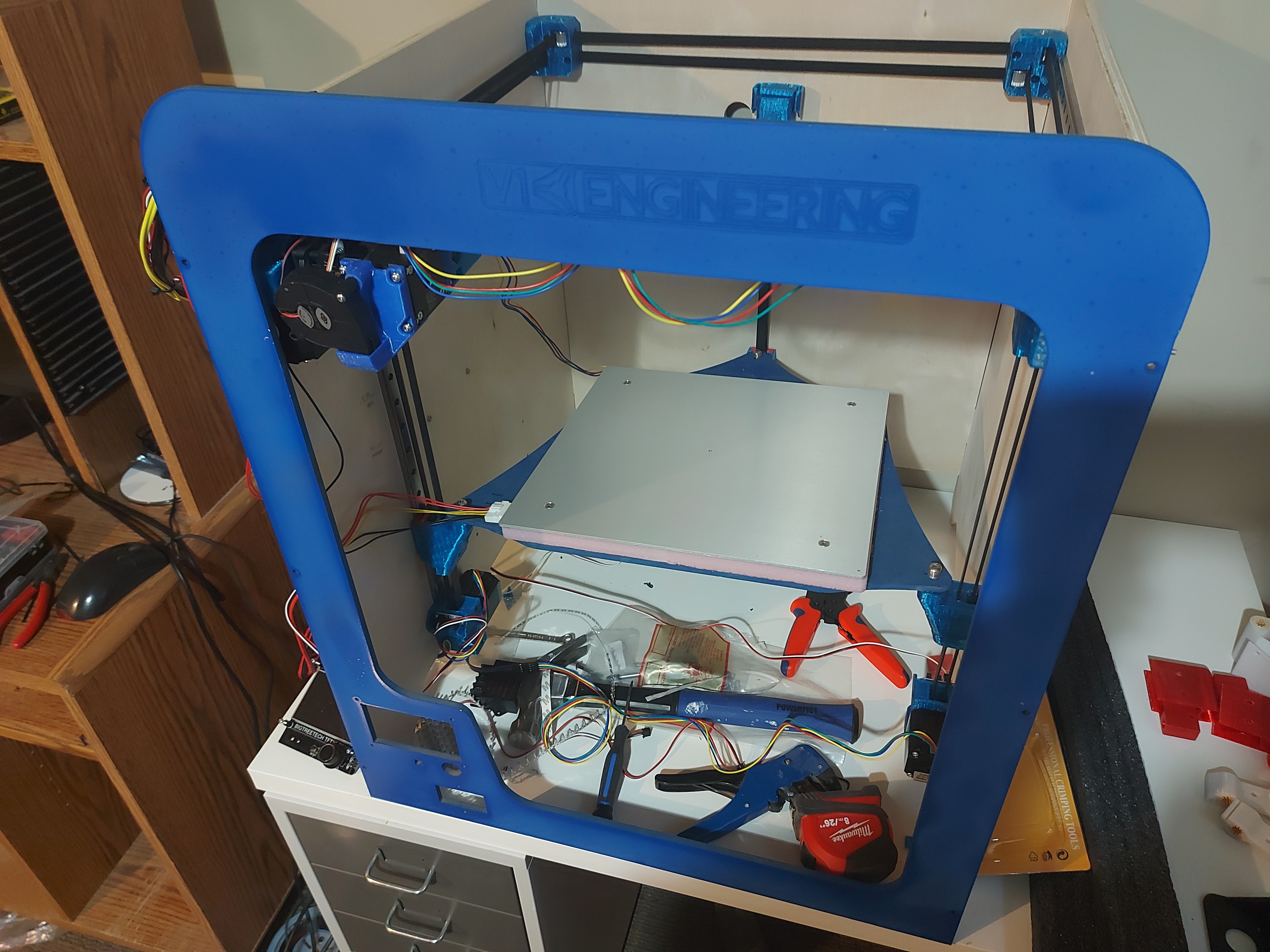
A coat of paint, just waiting for it to finish curing before I bolt it on.
It says I need to request access (which I did) buy you can share it so that anyone with the link can see it. Probably safest.
Edit: Z motors swapped, homing tested and working.
3 Likes
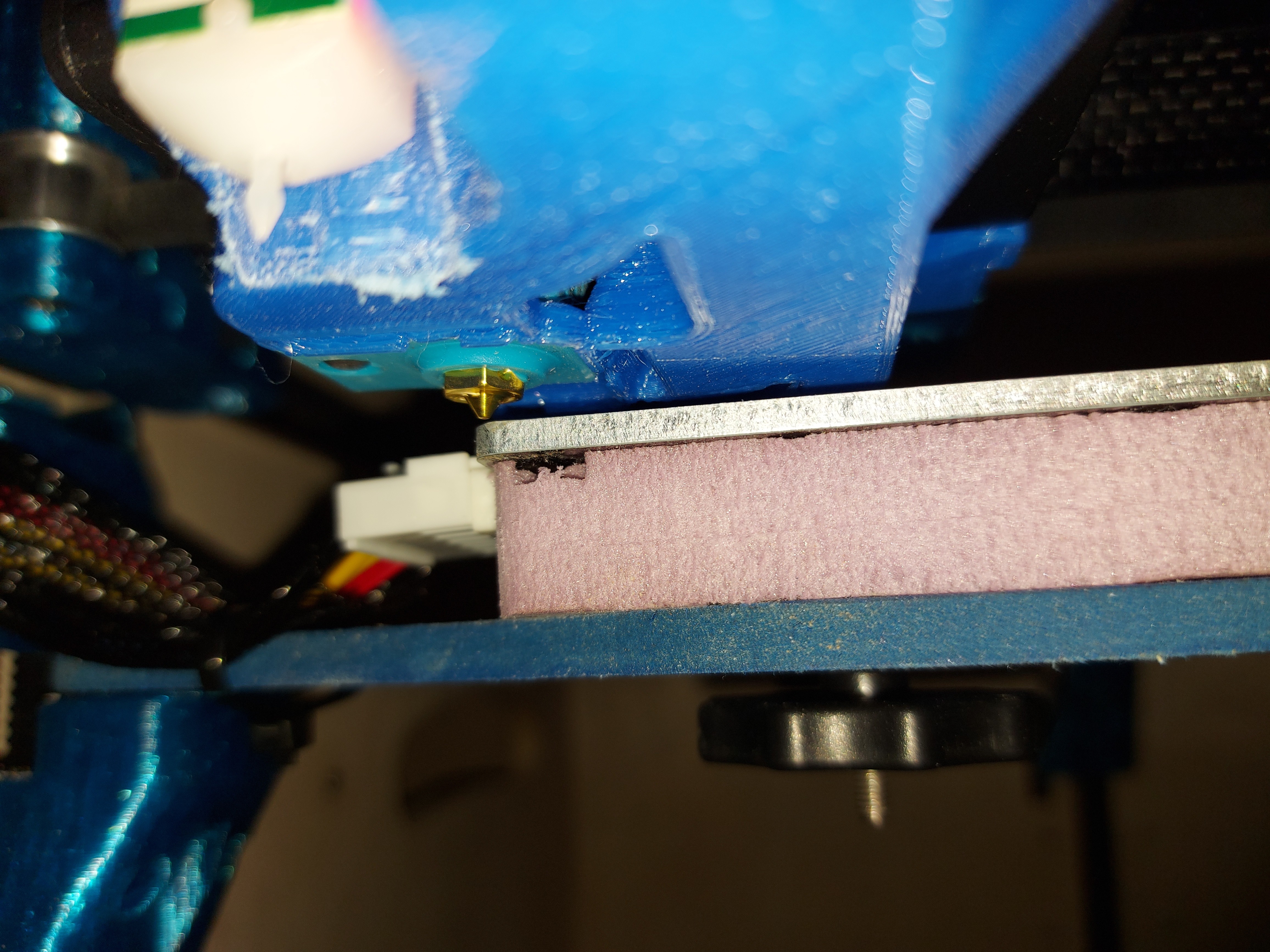
And there is my baseline reference for 0, 0, 0
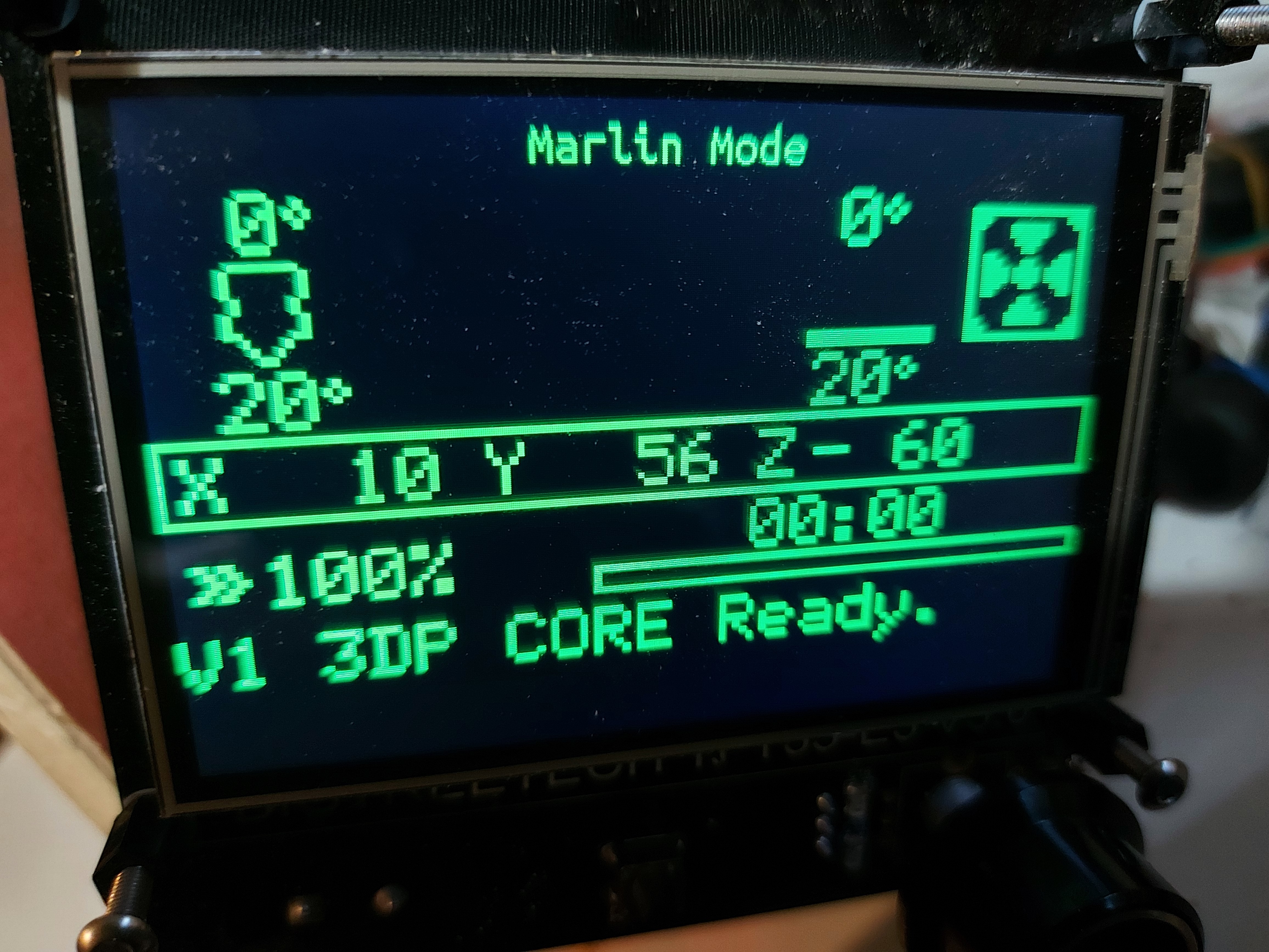
And this is the Marlin mode screen. So I have an extra 60mm of Z. My X and Y offsets from home are a bit different as well.
As a bonus, I still have enough extra in Y thst the BLTouch should be able to probe anywhere on the bed at all that I might think about reaching with the nozzle.
I’ll do the bilinear leveling as well, so I have to edit the coordinates of the mesh grid, as well as determine X/Y for the 3 point ABL.
I have a kendo practice this evening, so not sure if print testing is tonight or tomorrow, but coming soon!
5 Likes
It’s printing… But I am having trouble getting the prints to stick to the PEI/steel sheet. Not sure if it’s surface temperature or the plate just needs to be printed. Very frustrating after waiting through the G34/G29.
It’s really fast when it’s trying to print though, and the Hemera is amazing. Almost no drool at all even through the hotend is 250° through the whole proceedure. Fantastic control!
I’m going to do an isopropyl alcohol wipe-down and try printing again so I can register for a serial number. (Not done, still lots of cosmetic stuff that needs finishing, but functional.)
2 Likes
Okay, I don’t understand something…
I consistently get a bit under 2mm of printing, then the print head picks the piece up off of the bed. I think when the bottom layer cools just enough, and it completely lets go.
I looked at my first 2 prints, and throught that there wasn’t quite enough “squish” there, and maybe that would do the trick. I reduced the Z probe offset from 4.75mm to 4.65. Same result, and an identical looking first layer. Ok. Maybe a little more. 4.50. Nope. 4.2? That ought to have the first layer squished right down. Nope. no visible change at all in the first layer.
I don’t want to change it more, because I don’t want to crash the head into the print bed, so I’m looking for suggestions.

if you’ve got 10 minutes or so…
So first off, the G34 only uses the front left area of the bed… But still works. It has taken as few as 4 iterations, typically seems to take 7 or 8. I tried adjusting the probe positions but no dice.
G29, on the other hand works brilliantly, covering right to the edges of the printable area.
I’ve got 6 pieces now of the bottom 1.3-2mm of the same print lifted off of the bed. I don’t think I’ll give that bed surface purchase a very nice review on Amazon… but it could also well be that there simply isn’t enough squish. All 6 pieces, the first layer looks like it isn’t making good contact with the bed material, the “laying on top” look. Visually, there isn’t much gap between the nozzle and print bed, it doesn’t seem much different from my other printer (Also using a similar E3D V6 heat block) which has no such issues.
I was pretty sure that the probe offset should adjust the distance from nozzle to bed after completing the G34 and G29, but I’m not seeing a change. I’ll try compiling that change into the firmware. I’ll also look one more time for the G34 probe coordinates. I’m sure that closer to the edges of the print bed would produce better results, but that’s lower priority, since … it works.
Have you tried isopropyl alcohol and some steel wool? PEI sticks very well to PLA for me after that treatment (I keep alcohol wipes nearby to give it a boost every dozen prints or so, but steel wool is for a bigger refresh). I use 60C and it sticks well, then pops off clean when it cools. I can even get it to stick when the tool is too high and I get a little inverted elephant foot.
How are you adjusting the Z offset? M851 works. But you should also enable babystepping. You can use the screen (double click, IIRC) and adjust it while it is printing the first layer.
It may not be PEI. Looking more closely, it never actually says what the coating is.
I did clean it with isopropyl, it wasn’t enough to make a difference. No sticking. Even if I squish it down. I’ll see about getting a 12"x12" PEI sheet so I can have actual bed cohesion.
Nuthin’ is ever easy…
I haven’t tried PEI with PETG. But I have seen some people say it sticks too well and others say it is fine. Just be aware of that. I know you like petg.
Yes, and I use a PEI sheet on my current main printer. It does stick somewhat aggressively, but isn’t too difficult to separate. I put a buildtak sheet on the MP3DPv2 and I found it more aggressive than I like with PETg, and even more so with PLA.
I did buy a PLA spool, but it went with the MP3DPv2. I didn’t have much luck with it, but I was trying to print too hot. I still have an older PLA spool. Maybe I’ll try that with lower temp settings on this build surface. Just gotta pop it in a low oven for a couple hours to dry it.
1 Like