The Hemera comes with its own screws, I just used the ones in the bag. Well at least mine did.
I only saw 4, which I used to attach it to the tool mount. None left for the fan shroud. I’ll look through again, but that was all that was in the bag.
Oh man that is a bummer. I did buy 8 of those things so I guess mine might have only come with 4 as well. Sorry to get your hopes up.
You can edit the fan shroud to make the holes thicker to accommodate the screws you have. I should probably edit it to fit the M3x10 I use everywhere else that is not an M5. Thanks for the info.
Ohhhhh man people are going to hate me even more now. With CAD available I need to be careful not to tell everyone to just fix it themselves…
4 Likes
Mostly, I just don’t want to re-print the part before I have fan cooling so that the bridging isn’t so poor. (Actually, I think my printer did reasonably well considering the distance it had to bridge.) I do plan on re-doing the part. Maybe what I’ll do is edit the .STL for the shroud, and fasten it with some quick 'n dirty 2mm washers for the time being. The fan shroud has more room for that than the mount, so it ought to be fine.
Yeah, I think that the tool mount plate is fine as-is. If you still have some tweaking to do to the fan shroud, maybe editing it for the M3x10 screws would be best. This form looks good, and the BLTouch mount looks great.
1 Like
I was worried about that bridging as well, I had originally made it without the inner ribs, and surprisingly it still worked for me.
This is the best excuse to open source something.
3 Likes
Probably fine with good part cooling. The bridges aren’t untenable, but I never did get part cooling working right for mounting on my printer. Since I design with minimal overhangs, it doesn’t present large problems, though I ended up needing large overhangs for… part cooling pieces… so I never finished them.
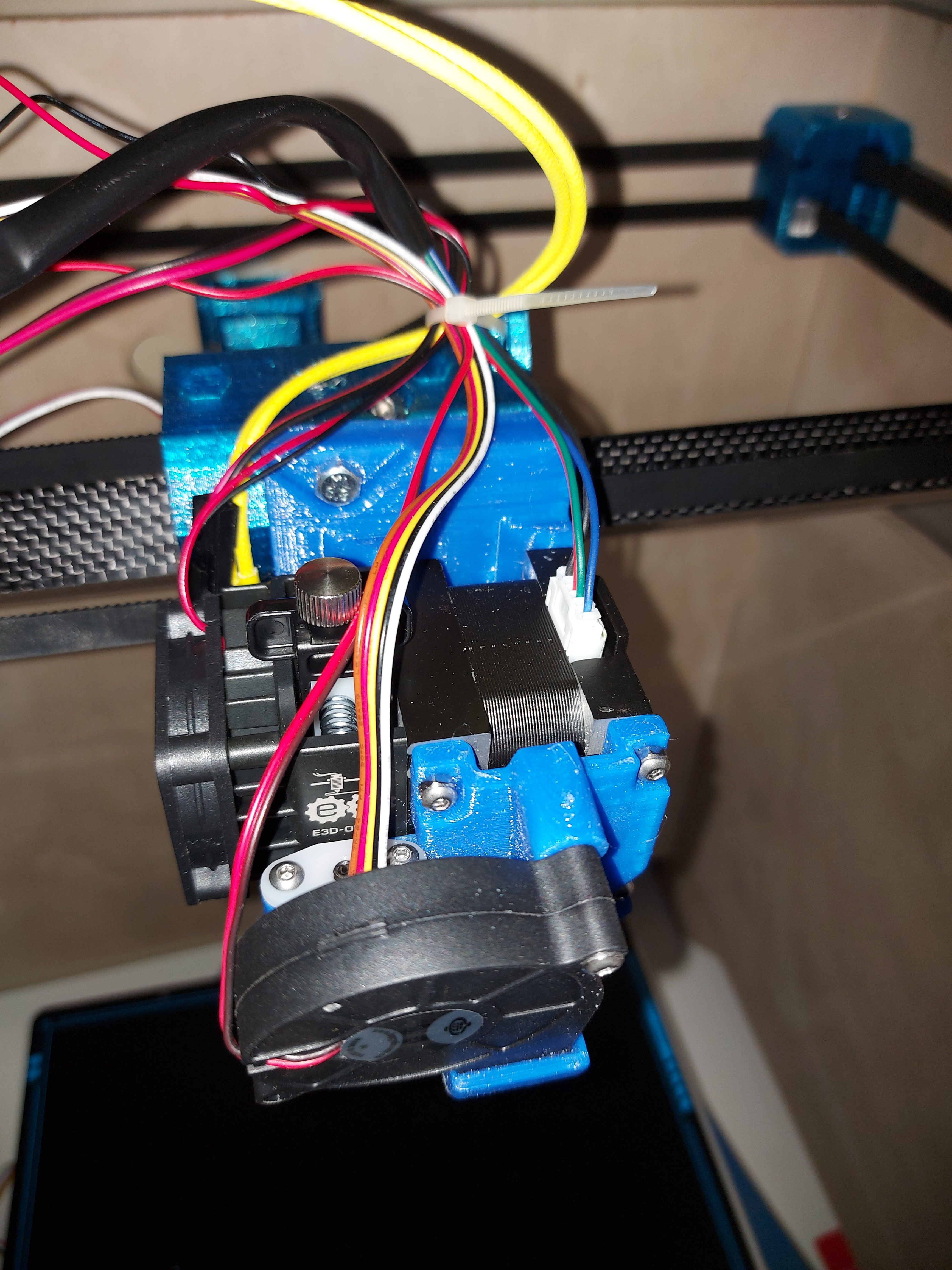
I have a big ol’ mess of wire now.
Extruder motor, heater, thermistor, hotend fan, part fan, and BLTouch clone. I’ll tighten and clip the zip tie when I get the sleeving over that. I ran out of the stash I had doing the LR2, and even then I barely got any of that done.
I’ve been procrastinating on making extension harnesses, only got one done. I gave up on my old crimper. It just won’t get the connector tight enough to fit in the housing without too much work. I have one that got good reviews in the box, but haven’t pulled it out. I should do that before the return window closes, but the very thought of all those crimps is so de-motivating.
2 Likes
I spent a few days moving the board around trying very hard to minimize extensions. In the end when it is done…very worth it.
1 Like
The X endstop can be routed over the back like you have it, or you can wrap it under and run it up with the heater and thermistor.
1 Like
So the last thing I have wanted to do to that mount was add a wire harness on the mount part instead of the tiny one on the hub. That orientation of the fan is a little less noisy than before but I still want to try and mount it flat under the hub, that would increase airflow significantly.
1 Like
The problem is that I made it so much bigger. Even the wires that don’t need extensions are only just long enough. There’s not a lot of extra wire there. That 100mm extra doesn’t seem like much until you add it all together, then it’s massive.
I had considered that routing for the endstop, but I get paranoid about any wire getting nearer the hotend than it absolutely needs to be. I ran over a wiring bundle with the hotend once, and it cost me a Duet board. Since those aren’t cheap, I’ve been a little more careful about keeping wire away from it. I’m sure that it wouldn’t pose a problem, but this way seemed a little more straightforward. I have plenty of room back there, too
A wire tie location on the tool mount would be good. I almost ran the wires up in between the screws for the Hemera, but that seemed to keep them close to the heat block a little more than I liked, and the clip for the E3D thermistor wouldn’t fit nicely anyhow.
My main worry about mounting the fan flat would be that it could only suck hot air from right over the heated bed. I suppose that the increase in flow might make up for it, it’s not like the heated bed is hot enough to keep the plastic molten, like the extruder does. Also being out of the way like that would be pretty awesome. Well, I’m more than open to printing some new parts, I was planning on doing so anyway.
I ended up using an extra 3mm nut (I have literally hundreds) on the end of the 10mm screws, since they’re almost exactly 2mm thick. That way I didn’t need t print washers. That holds the fan shroud securely, and doesn’t stick out too much. Fortunately the button-head screws don’t stick out as far as the cap head screws, so everything still fits nicely. Everything around that core is packed in nice and tight. I’m really interested to try printing in TPU, which the Hemera is supposed to excel at.
I think I’ve figured out the best place to put that extra pass through into the side of the case for the LCD and Z motor harnesses, so I’ve got to see about cutting that out and making it look nice.
I have a package of aluminum cable ties with an adhesive pad around somewhere. I’ve been looking for it a couple of days, but they’re not expensive, so maybe Ill just go buy another package. I wanted to make a trip to Princess Auto anyhow.
Funny, I realized that I’ve connected up one of the SKR Pro boards before, but I really don’t know where most of the printer stuff goes. I need to hook up stuff like the heaters, fans and thermistors, not to mention the BLTouch, and don’t know where any of it goes. Well, it’s not like Google can’t find hundreds of wiring diagrams for it.
1 Like
If you stick with an open top and front, and your room temperatures are below about 22°C convection should take care of the rest I reckon,
I should add that my enclosure misadventures have shown that there’s a wide variety of climatic influences when it comes to print cooling. In colder climates slowing down the rate of cooling seems to be a thing (along with “I can’t keep my bed hot”) whereas where I live, the opposite applies. Internet wisdom offers a “one size fits all” solution, based on the localised experience of the commentator so when it comes to cooling at least, don’t listen to anyone else.
I still think you’ll be OK. ![]()
When you’re talking about plastic at 200C, a bed at 60C and ambient near 25C, you could at most lose 25% of your cooling. That sounds like a lot. But that is assuming the air is either 60C or 25C. It will probably be a mix no matter which way it is pointed.
200C-60C = 140C (worst case)
200C-25C = 175C (best case)
175C/140C = 1.25
The cooling is proportional to the difference in temperatures.
3 Likes
And where the intake is now it gets a lot of warm air off the extruder fan.
2 Likes
I saw that. I kind of wondered why the fan wasn’t the other way out, but… same thing. There’s really nowhere near the hotend that the air is going to be actually cool…
Most of the time I print PETg, and run temps a little higher. Bed at 70° and hotend at 250°, but this makes even less difference then. You’re right, it’s the delta that makes the difference, and I know I’m chasing an irrelevant factor.
Not much progress today. I putzed around with wiring, and cut a foam insulator panel for the heat bed. It was made from some 1/2" foam that I bought some time back.
The LR was acting badly. It kept disconnecting the X motor. The plug on the SKR Pro board really doesn’t like that one extension, so I cut it off, and replaced it with a JST XC connector, which should take care of the problem for once and for all. I ended up with 3 insulator panels, only one of which didn’t have gross errors in the X dimension. (It only had a minor error, which was within allowable amounts.) It would be 100% unacceptable for many things that I want to cut, but I was out of space, and I could make it work. Unfortunately, that about did in my will to do more crimping, so…
The new crimping tool that I bought does seem much better though. The old one there was a very fine line between “It won’t fit in the connector housing” and “Oh, It severed the wire.” – one that I almost never got right.
Somehow I scratched up the paint on the front panel. I’m a little bummed out about that. Maybe I’ll just cut a new one, patching up that paint seems like it could get really annoying.
1 Like
Do you have any more stickers?
1 Like
As it happens, yes. I am also considering just engraving the V1 logo.
There are some other improvements that I also want to make. Room for a light switch for the LEDs, for example.
4 Likes
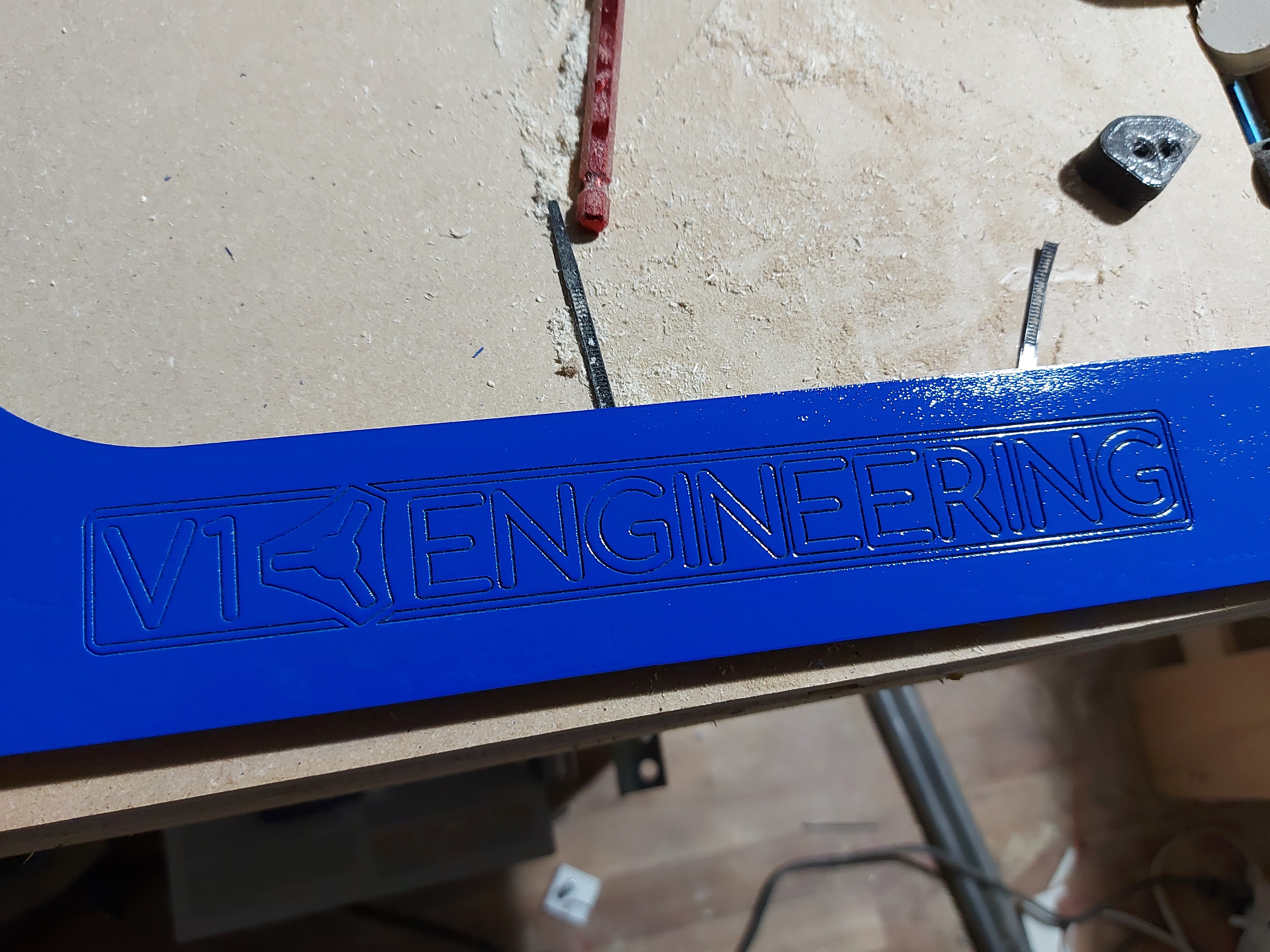
I thought the scratches were deeper, but apparently not. A quick touch of 300 grit sandpaper seems to have done the trick to smooth it out for touch-up. Did the engraving anyway, just to see.
7 Likes

awwwww I love it!
1 Like
And… it moves under its own power.
The endstops don’t seem to work right. They all report triggered. I have little green lights on them that don’t change.
The BLTouch isn’t plugged into the servo circuit.
Moving at 7200mm/min commanded seems good. Not sure what the firmware speed limits are, but it all books along nice.
I have not been able to get the fancy bed levelling, because the endstops are wonky.
Guess I should look up which fan is what, and where the BLTouch servo connector goes.
Looks like I have to make a new front after all though, the part fan will crash into the header for the one I did. It protrudes about the thickness of the fan past the front of the sides. I suppose that I could make an extended flag, it’s still well forward of the print bed if I push it back.
The wiring sure ain’t pretty, and I need to connect the fans still, but it’s almost functional. I need some more sleeving and a couple dozen zip ties, but it’s super close.
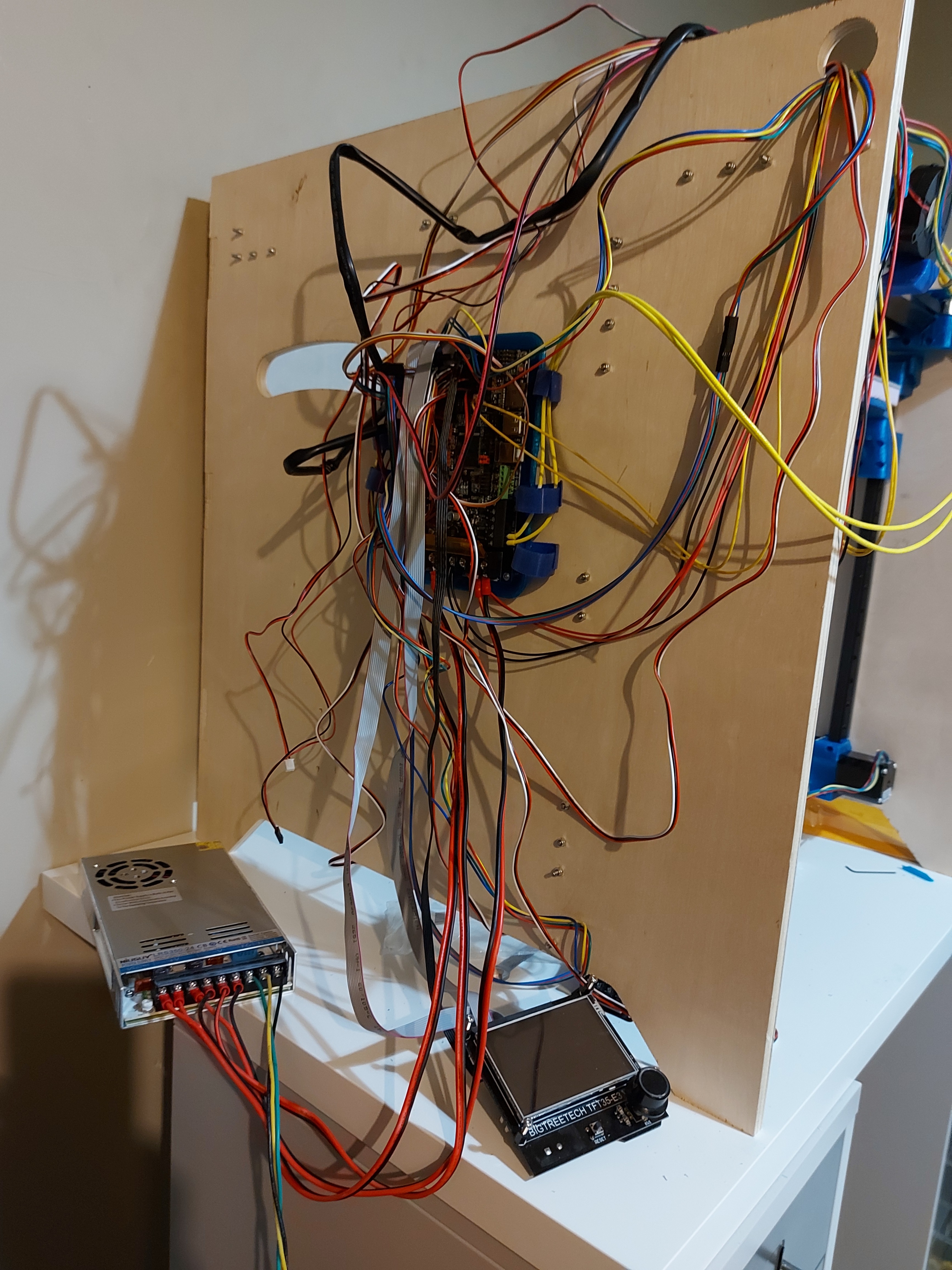
There we go, huge mess as a starting point before I make it better.
2 Likes