Bit random, but feel like the right people are here. This is for one of my CNC/printed projects, an updated version of my Servo based Wood Tile Display.
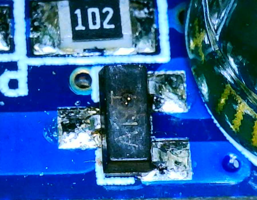
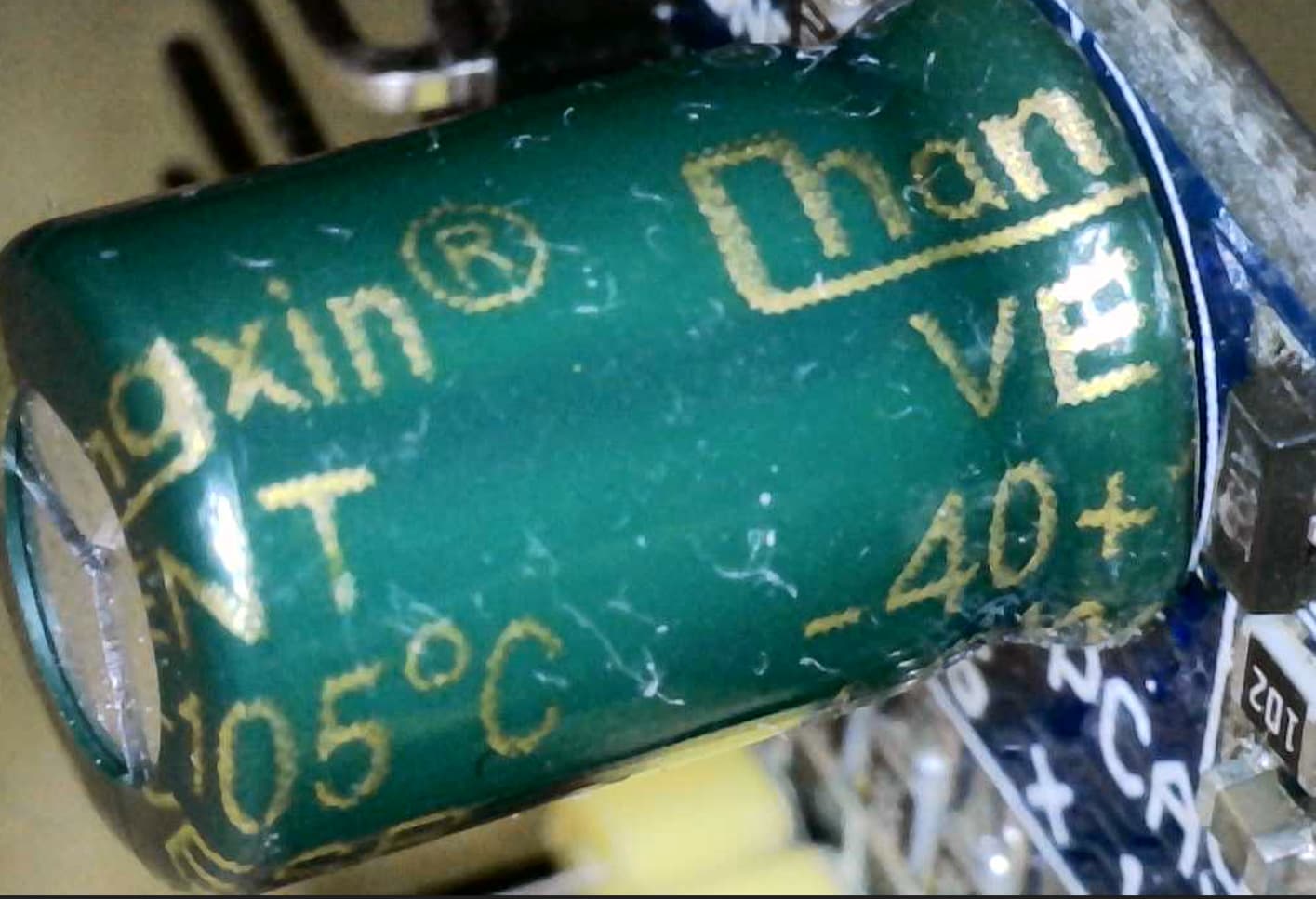
Curious if anyone here is familiar with I2C PCA9685 based boards that can be used to connect up to 16 SG90 servos per board? Found any reliable ones? Am using ones from amzn with unlabeled mofset for reverse voltage protection that fails with unknown lower than expected current…
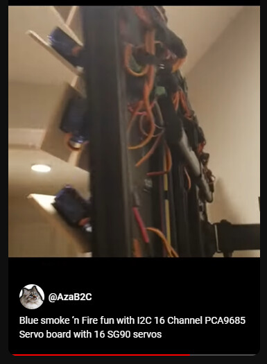
Managed to burnout 12 of these boards earlier today. Managed to actually cause one to flame . Example smoke…
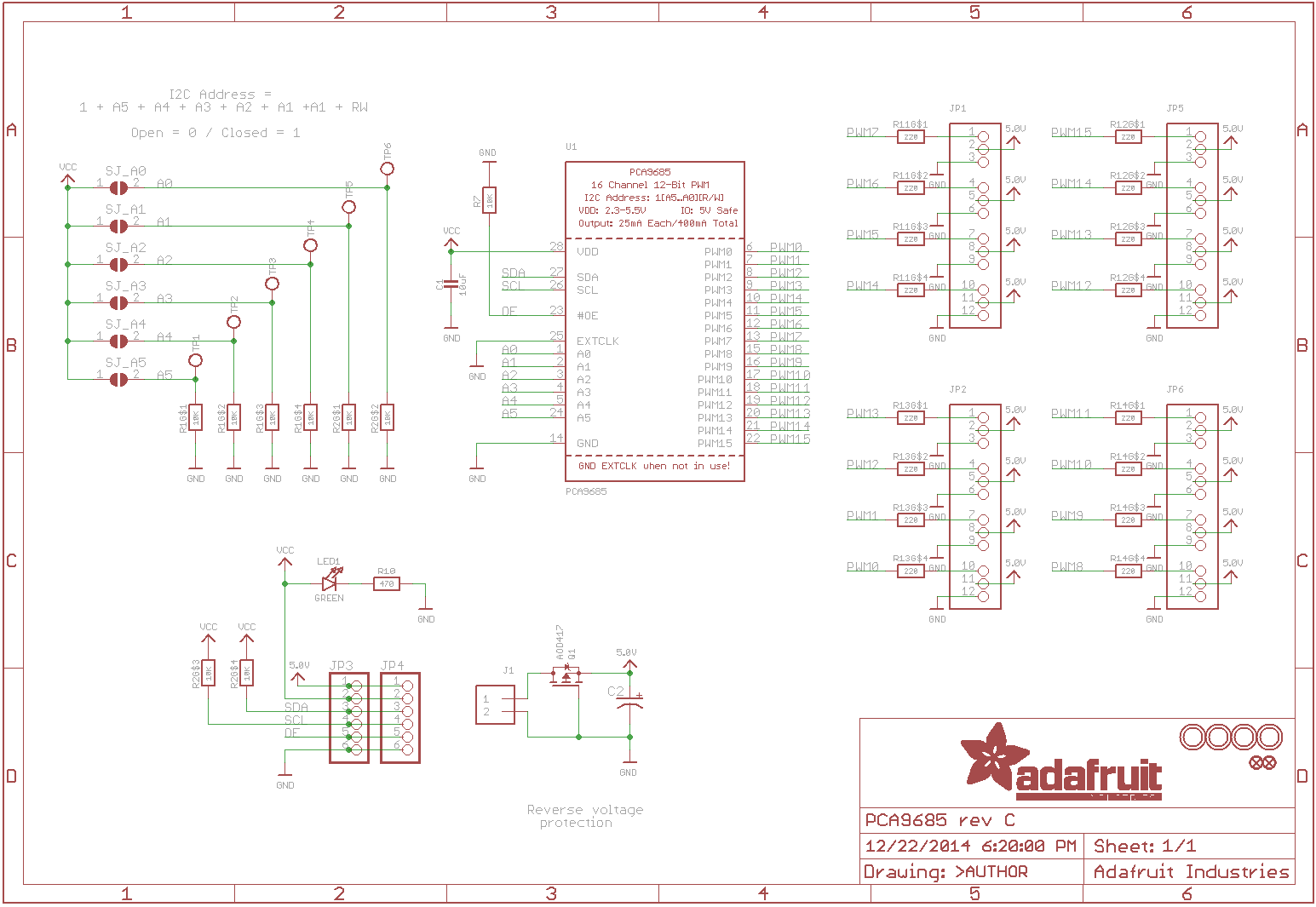
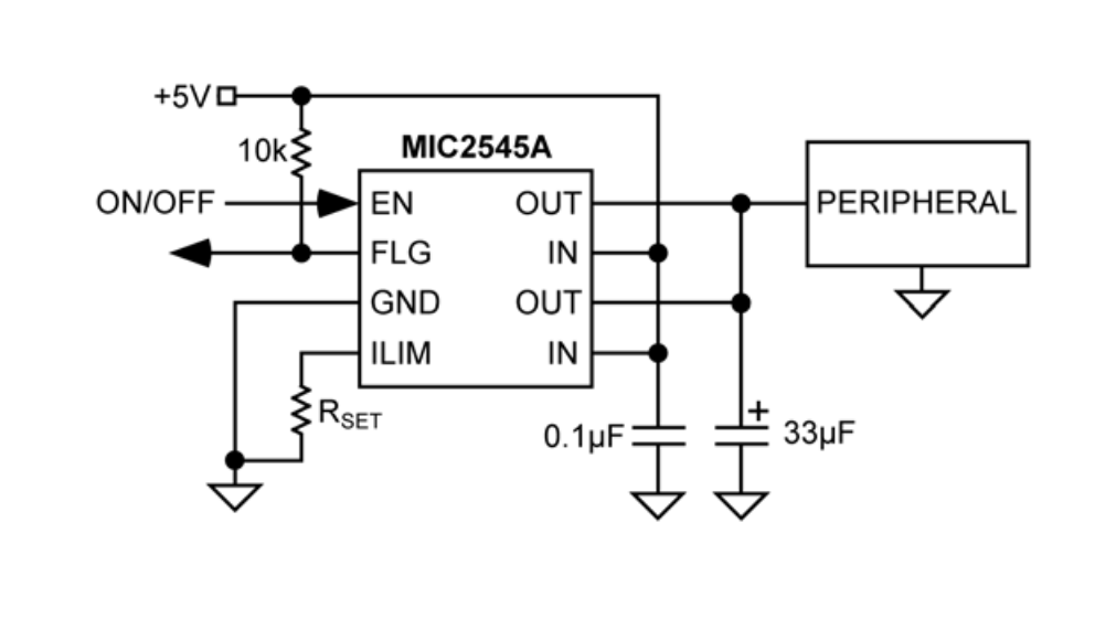
Schematic for Adafruit’s board, the knock off versions I’ve been using are 1/3rd of Adafruit’s price…
Smoke was caused by overwhelmed mosfet when the Servos were in a current hungry Stalled state.
Currently planning to salvage the boards and bypass the reverse voltage protection… The main PCA9685 ICs seem unaffected. Ideally these servo breakout boards would have efficient current limiting IC, or polyfuse or something else (?) that caps current that stalled servos can consume.
Will be changing code to aggressively use enable pin to de-energize servo breakout boards not actively moving, and some other coding based options.
What are you expecting to see in terms of current draw? What are the markings on that FET?
Honestly, that’s a truly horrible way of doing the reverse voltage protection. What I suspect is happening is that you’re browning out your power supply which is dragging the voltage rail down and causing the FET to partially turn off.
Another issue is that this FET isn’t really all that great for being driven from a 5V gate. At 4.5V and high junction temperature it’s more like 100mR on-state resistance, so having the loss through it on a stall is heating it and raising its resistance which will make it heat further etc.
It’s a slightly annoying package to jumper across, but I’d clip the legs off with side cutters, remove the entire device by heating the tab with a soldering iron and then, depending on the layout, either put a bit of wire or a blob of solder from drain to source.
The second aspect is definitely the stalled servo current issue. Typically you’d have some form of controller that can detected the locked-rotor current and either turn the channel off or lower the current through it to a lower maximum.
What are you trying to accomplish, here? Is something preventing the servo from moving unexpectedly or is the servo capable of a wider range of motion than what it’s driving?
Not sure how a stalled SG90 should affect the PWM input line? How are you deriving Vcc? As per the schematic, Vcc is not the same as 5V, which is why the IC does not appear to be damaged by the smoking mosfet. The chip does not regulate the servo current at all, it just supplies the PWM signal up to a maximum of 25mA per line, protected by the series limiting 220 ohm resistor. If you want some form of stalled servo current protection it needs to go on the +5V servo supply, not Vcc.
A single SG90 should draw around 650mA @ 5V when stalled.
Thank you @jono035, I appreciate your input and suggestions.
~10ma * 16 servos = 160ma when idle (common scenario)
~250ma * 16 servos = 4A if continuous motion (rare scenario. Expect subset of 16 servos moving, and slow movements at any given time).
~750ma * 16 servos = 12A if all fully stalled (Should never happen, but… Code Bugs… So will happen when software has bug(s)).
Electrical wise, 12A is too much, goal would be 5A limit. Am currently looking into EFuse, PolyFuse, or some current limiting IC, or circuit, that caps current to no more than 5A. My EE knowledge is limited, so hopefully someone will tell me if this doesn’t make sense, and whether to try something else? Ideally, would like to make the circuit protect hardware against coding mistakes, mine or other people’s… (v1 project is open source, and this v2 will be too). Prefer the Servos to temporarily stop or weaken rather than exceed 5A budget per cluster of 16 servos.
Code wise, am looking into aggressively using enable to disable power, and code to make limited slow movements as much as possible. Staying within physical bounds to avoid servo stalling trying to push against immovable object.
Looks like A19T to me, P Channel mosfet, guessing supports continuous current 4A based on specs for similar. I can’t find official schematic/BOM for this knock off board from amzn. My first post had schematic from official Adafruit board, this board definitely doesn’t use the same component.
Cheers, I will try to detect and mitigate brown outs through intentional software coded behavior/limits, and hopefully sensor(s) too. Am checking PSU specs (MeanWell RSP-320-5) for options. Have a current sensor somewhere intended for this project and situation, looks like I need to dig that out.
Appreciate reading your suggestion, was heading down this path, validation on this option from you/others has increased confidence in my understanding.
Makes sense, am making code changes to impose more limits. Doing smaller scale damage controlled dev/test going forwards… It was awesome to see and hear the all 192 Servos rapidly moving around, right up until I killed mosfets on all 12 servo driver boards
Watching for brown outs and might eventually add another PSU after getting slow motion reliably working.
Goal is to play Tetris, Snake and other Lo-Fi games on a wood tile display. Pretty patterns, time and such, tech art. Camera for lo fi mirror/interactive stuff. Inspired by Daniel Rozin’s work.
Plan is to apply Servo management knowledge to more practical projects.
Yep, Servos are physically software limited to just ~60 degrees of freedom before the top or bottom of the tiles hit the back panel. Actual freedom of movement is even less than this because the cheap Servo behavior/quality varies significantly. Will write some calibration code to align everything.
Yep, VCC is being fed from a 3V3 pin on the Pi 4. Where as main power connector (J1) has 5V coming from the MeanWell PSU (RSP-320-5), with common gnd. So, the reverse protection mosfet blowing prevents power to the Servos, but the PCA9685 IC continues to get power from the 3V3 VCC line.
Yep, code changes, and this is what I’m digging into… Efuse, PolyFuse, current limiting IC, or something else?
I don’t think it is, I think the board is being used to distribute 5V and that’s smoking the input protection FET.
Right, I see where you’re going with this now. Polyfuses are a rough part to design with. They work best when you have HUGE margins between trip and hold current. Something like 100mA normally, anything over 1A is trip. There are other options like using a current sensor in-line and then coding your own over-current cut-out.
I think probably the simplest approach is either to bypass that FET and rely on the current limit of your power supply or to distribute 5V separately. If you don’t implement any form of current limit with this it’ll stop blowing up boards but still potentially leave you able to overheat the servos. The ideal case would be an individual current limited ~300-400mA supply per servo. That way when they stall, the power supply just keels over and goes into over-current mode. A next best could be a few 1A supplies driving a few servos each. Moving to a separate 5A supply would be a possibility, meaning that 1-2 stalled servos may smoke eventually, but if you stall more than 5-6 at a time it’ll fault out.
Alternatively, adding something like this:
That would allow you to monitor the current and potentially detect a stalled servo condition and disable everything before damage occurs. To start with, it could simply be a ‘too much current, disable everything and light a fault LED’, with that limit slowly being raised until you’re comfortable. Then potentially you can implement fancier fault methods where you can implement different current limits based on whether there is motion occurring or not. This can be as simple as the current limit being checked in a timer interrupt at something like 100Hz rate using the latest ADC sample and compared to a limit. If motion is commanded, raise the limit to 4A. If no motion is commanded, lower the limit by 0.1A per interrupt until a minimum of 500mA, say. This way you’ve got headroom for motion, allowance for some settling time and a slowly falling lid on the allowed current that assumes things will settle to the idle state. For debug/development you could output the current limit via a PWM channel +filter or a DAC channel and then watch both the current sensor output and current limit using a scope. That makes it easy to visually see what a ‘good’ condition and ‘bad’ condition are and to tune the behaviour accordingly.
From what I’ve seen of how most servos are designed, the servo itself is used to limit the range of motion. So for instance if you’ve got a 180 degree rotation servo, the linkage is designed such that the horn on the servo could move 200 degrees, for example, or if a smaller range is needed that moving it beyond that range simply starts to wrap around on itself. That kinda thing. I don’t know if you’re at a point where that’s an option, but that might be worth considering for the future. Also compliant mechanisms, things like that could also work.
Oh dear, that’s a MUCH smaller FET than on the Adafruit board. Good grief. Those tiny SOT-23 FETs (that’s the name of that miniature 3-lead package) are really low power handling units. The only way they can say things like 4A continuous is because they turn on with such low resistance. With smaller parts like this, they can still have high performance but it’s a real balancing act. You can maybe only dissipate a few hundred mW in them safely, but that’s ok because they’re so efficient when operating correctly that you can get a few amps through without dissipating more than that. On the other hand, when something does go wrong you’ve suddenly got no power dissipation margin. They also have very small dies internally which don’t have any thermal mass. If the FET partially turns off or doesn’t turn on fully because of gate drive issues, or if you get a big pulse of current due to something shorting out and discharging the capacitors through it, that power will very quickly overheat the die and that’s when the smoke comes out.
If it’s being driven the same way as that Adafruit one, as soon as you get something that browns-out the supply then it’s very, very dead. I don’t like the way the Adafruit one is doing it, it’s not what I would call a professional approach, but at least being an Adafruit design you can be confident it’s somewhat fit for purpose. Taking that design and then cost reducing it by putting a smaller, cheaper FET on is a good way to make it no longer fit for purpose. Wonderful example of crippling a design to save a few cents.
I only just figured out why you killed 12 of them. I had assumed you were just swapping a new one in each time and was honestly impressed by your tenacity while simultaneously being concerned about your troubleshooting method!
Yeah, I think that this decision is probably the root cause of your issues. There’s kinda a hierarchy that I try to apply when designing things. The best case scenario is that you make something where failures cannot occur. This could be things like carefully choosing lower torque motors for a linear motion stage so if it does crash it just stalls. The next best thing is mitigating that in hardware. That could be something like having a much higher power servo based system that can easily tear itself apart but adding end-stops that cut power to the drivers or trip a hardware interlock circuit, that kinda thing. The next best beyond that is something that uses software sparingly and in a way that’s straightforward and easy to test. This could be something like using hardware endstops that trigger an interrupt in software. There’s still plenty of option to muck things up by having code that gets stuck in a blocking state or getting the interrupt priorities wrong, that kinda thing, but it’s a lot easier to verify correct function and prevent regressions. The worst case entirely is to just deal with it purely in software. This would be something like using some method of homing and then just driving around open loop with software limits set. If something does bind or you’ve homed to the wrong position, or the software has a rounding error that slowly causes an offset over time etc. then eventually you’re going to find that minor software error by dealing with the aftermath of the mechanical destruction.
It becomes super important when you’re dealing with big power stuff but applies equally in other cases. Basically anything where a failure can cause damage to something or create a hazard, it’s important to design for that up-front because it’s not only expensive to keep breaking things, it’s also slower to recover from and harder to test for. If it’s a case of something freezes and needs a reset, you can cause the fault, reset, try a fix, fault happens again, reset etc. maybe even 100x over the course of a couple of hours. If it breaks hardware then it might take anywhere from 10 minutes to multiple days to fix. We had a preventable failure a little while back due to operator error that should have been caught by software protection that destroyed maybe $2-3k of components and took almost an entire week to recover from. It was a failure that is very difficult to protect against in hardware but relatively easy to prevent in software. The issue was that the software was being iterated on and had things like protections being disabled by commenting out sections of code so that other parts can be tested. That’s the kinda thing that really stings because it’s so easily preventable. We’ve started using a few other methods to make sure that it’s clear whether the code is running a debug version or not.
A lot of this is an extension of the FMEA (failure modes and effects analysis) concept that’s used in industry where we go through an exercise of categorizing as many possible failures as we can identify then ranking them in terms of how likely the are to occur, how easy they are to mitigate and how hazardous they are if they do occur. Something that scores highly in all categories is very back. This might be something like a failure where a component is designed such that it can be installed incorrectly, that it’s difficult to accurately test for during assembly, that it wouldn’t cause an issue in normal operation but may also be critically important for protection during a fault. In that case, you’d look at that and go ‘well, we need to redesign the system such that it uses a different component, or that they component maybe becomes part of a sub-assembly that makes it end-of-line testable, or that the we add test points that make it externally testable or add circuitry to make it self-testable’ etc. On the other hand, if the failure is something like the display gets corrupted, that it only happens on a weird power glitch state and that it self corrects after a few seconds, that would get a low score across most of the categories and wouldn’t be as important to fix.
@jono035 thank you for all the info, so much info, I had to read multiple times to fully absorb. Trying out some of the things you suggested… Including looking into current limiting sets of Servos. Will take a look at alternative Servos if I end up doing another build. Will report back, and try to capture the next round of smoke/flames too.
Am “Repairing” some of the PCA9685 boards, removing mosfet and soldering stranded wire between +ve traces, then snipping excess. Ordered more PCA9685 boards from different suppliers, noticed some don’t have the mosfet at all, 5V connects direct to the header pins.
No worries, it’s a bit of a brain dump and I never quite know how much or how little detail to go into so I’m 100% expecting that you might need clarification
I had to reply to this in particular, as I was thinking exactly the same thing as I read along.
I’m curious why the servos are physically limited to 60 degrees of freedom instead of 90. Wouldn’t 90 be better as a pixel?
Pretty much this- though I’d add that it would be far better to make sure that the servos are not able to get stalled in the first place- either by limiting the commandable range of position and/or making sure they are mechanically unobstructed through the ranges that you can command them.
Yeah, 100%. That’s exactly what I meant by saying that it’s better to make it so that the fault cannot occur than to try to detect the fault.
It looks to me like a project where there’s a significant amount of mechanical effort already invested so I can also see why taking that many steps backwards to fix a design flaw like that may not be feasible.
Yeah, the ~60deg is software configurable, for larger angles I found shadows and servo innards being revealed for excess angles was diminishing the ‘pixel’ effect. Not very scientific , but that was my observation/logic.
Yeah, makes sense, definitely making code changes… Also, I should’ve tried looking for alternative Servos with lower torque/current instead of just going with best selling-cheapest ones available (I did try ~4 different versions at the time). I’d definitely design/build this differently if I was doing this again from scratch today. Bought 1st 3D printer in Jan '21. v1 of this project was built the same month. v2 was physically built later that year. Dusting off and updating/upgrading in part to take to Open Sauce if they’re interested.
I appreciate this, and will be more mindful for future version, and other projects.
Yeah, there’s a bunch of stuff I don’t like, but… all things considered, am on the path to use duct tape and baling wire to make this ‘done’ and work good enough for now.
I wonder if there’s a suitable programmable high side current limiter that would work for you.
You have too many servos for something like a MIC2545A to be useful (It’s $5 per chip)- but that’s an example of a way to handle downstream current limiting.
Am open to changing PSU for higher voltage if it’s more reliable/cheaper overall and enable using buck converters for sets of servos. If the buck converters that have over current protection that will temporarily brown out. e.g. 12V PSU, then use one 3A rated Buck per 8 Servos. Digging around…
That’s a really good point, I thought about that but I don’t think I ended up mentioning it. We frequently call these ‘point of load’ converters because they are matched to smaller loads around the system rather than needing to bother with distribution at target voltage. There are an absolute shed-load of them on AliExpress etc. that could work, but some of that may ultimately depend on how they handle over-current condition. It could well be that you just end up replacing your burned out FETs on the expansion boards for burned out DC/DC converters…
Perhaps something like this per 2-3 servos:
Although that may end up depending on how you’ve got everything hooked up as to how viable it is to add them all over the place.
Another option is that this kind of thing can be a great way to get into PCB design if you’re interested in giving that a shot. A simple distribution board that matches what you’re trying to do and makes it easy to get all the connectors sorted can be a great way to take a first attempt at it, or a great way to clean it up and make your life managing the project easier if you know what you’re doing.
Ultimately I have a few products that aren’t super far off that idea for commercial customers.
Yeah, have a bunch of similar DROK Buck convertors laying around.
LOL, am looking for the smallest excuse to rationalize making a PCB Will bread board experiment with some Buck convertors I have lying around. Test a few scenarios, then look at using this as an opportunity to learn more about making PCBs.
If you have store(s) that you think might help me and other readers, please consider sharing link(s) ? Cheers!
Seems like a pretty good one. Literally the simplest reason I’ve done them before is as an easy way to break out one larger connector to multiple smaller ones without needing to resort to stripboard.
I’d put some thought into adding current monitoring of the entire thing to your project, though. That’s likely the single simplest option for avoiding anything too catastrophic to start with.
This is all special purpose stuff that I’ve designed in the past for companies that I’ve worked with. If you’re interested, the one that closest matches this situation (power/signal distribution and cleaning up connector options) are housed in these guys:
It’s a pretty remarkable product and chock full of some massively impressive engineering. I’ve also done a bit of work on their safety systems previously but less of that over time as my primary job has gotten busier. The LED floodlight solutions for these are also mine, although that’s nothing really terrible complex, all up, that’s more an amusing case of huge aluminium PCBs and orders that consist of hundreds of reels of LEDs.
Wow, it’s like a bandsaw version of a SawStop, except without the pyro cartridge…
What a cool product that is.
Products like this make workers’ lives in industrial / commercial settings soooo much better.
Yeah, I’m a huge fan of it and really want it to succeed in the market which is one of the reasons I’m still helping them out. It has some incredibly hardcore engineering work inside. They’re a very ‘from first principals’ kinda company so it’s pretty fascinating to see what they come up with as solutions for things. They make a ton of stuff in-house and locally which is cool, too.
The comparison to SawStop is an apt one because there’s a similar product on the market from a competitor that behaves similar to the SawStop where the blade is essentially sacrificed. In the Guardian saw they have a crazy mechanism that rapidly de-tensions the blade and then slows it down, along with a bunch of ways to keep the de-tensioned blade under control. This means there’s no damage to the blade on a trigger and all you’ve gotta do is press and hold the reset button and it’ll re-tension and be ready to run again in something like 10 seconds.
Hearing about the differences in injury rates at some of the sites they have outfitted is insane. Things where they’re now basically injury free when previously they were tracking injuries in terms of cuts, minor amputations/injuries and major amputations/injuries in truly startling numbers. Really kinda leaves me feeling a bit queasy, honestly.
Their bigger saws are getting pretty hilarious. I’ve had owned cars smaller than some of these saws.
It’s a pity they’re so busy otherwise I’d be trying to get them to make a hardcore cabinet saw.