genius, it worked, thanks i had been resignated to do manual uploading hehe
my other printers just worked fine the other way around. (![]()
![]() )
)
genius, it worked, thanks i had been resignated to do manual uploading hehe
my other printers just worked fine the other way around. (![]()
![]() )
)
Crap. Was about to start printing the minimalist enclosure, but for some reason, the printer won’t do it’s pre-heat. It just sits there. It did just update firmware. Maybe time to do the klipper mod after all
klippermod 4tw
Actually looks like an Orca update bjorked it up. Ugh. Maybe need to reinstall all the Orca stuff from scratch.
Doug- question about the enclosure kit from Flashforge. Amazon is sold out, so i bought one on AliExpress, for $30. I just now realised it doesnt come from the official store- and lacks a new top cover for the hotend. The official kit is almost twice as expensive.
What is special about the new top cover that makes replacements necessary? and, in your opinion, can the old one be modded easily enough by someone with enough tools to open a harbor freight store
Sorry to ask here, but its so niche i doubt anyone has a quick an answer as you could give
thanks
Honestly, you don’t need it at all.
The whole reason, and the only reason, for its existence in the form they gave it, was to have their printer emulate the famous Bambu Labs printer. It came that way on the AD5M Pro, but not on the non pro version. Thus they sought to hook people wanting the DIY enclosure into buying it from them, or else have to use some DIY solution for that as well.
While it may be fine with the factory parts for it, when it came to emulating the strange pivot approach using a 3D printed appendage, it got weird.
When I first did the DIY enclosure, the very first thing I did after that part broke just by looking at it because it was so fragile, was reject out of hand all that weirdness, by designing and publishing this easier, simpler, faster, stronger approach:
Now, on my first enclosure, I laser cut my own panels and used my own screws. Used my part (above).
On my second enclosure, I bought a DIY enclosure kit from a third party, that did not include their replacement for the top of the hot end. Used my part (above).
On my third enclosure, I bought the name brand DIY enclosure kit from Flashforge, that did include their replacement for the top of the hot end. I still used my part (above).
Their weirdness on that is still sitting in a box waiting to be sorted and dealt with. I won’t be using it. ![]()
I once sang at a wedding in which an usher who lit half the candles, and who therefore first lit a candle lighter, had to also light a second candle lighter because the other usher had no matches for his own candle lighter. What’s sad and humorous is that he used matches both times, instead of just touching the first candle lighter to the second. It was as though, at that moment, fire only comes from matches. Later, the other usher’s candle lighter went out before his last candle on his side of the platform. In confusion, nervousness, and despair, and with the other, older usher whispering loudly from across the platform for him to “Just leave it!” he did exactly that. Instead of just grabbing the next to last candle and using it to light the last one, he walked away, as though, at that moment, fire only comes from a candle lighter. The entire audience was aghast until I walked from behind the piano where my wife was playing preliminary music, and lit the last candle.
I tell this humorous story to point out that the design tries so hard to create a fancy pivot that looks like a Bambu Labs approach, it forgets that there is a pivot feature already existing mere millimeters away, in the junction of every single link in the drag chain. LOL.
dude, rockstar. Thanks so much for all the info. appreciate it!
and looking at my printables list, I already downloaded it earlier when i was looking at the enclosure parts.
Flashforge Adventurer (AD5M) Runout Sensor - Bowden PTFE Coupler C-Clip
I used digital calipers to measure and recreate the C-Clip used on both sides of the runout sensor on the Flashforge AD5M because one of mine got sucked into a clip-eating black hole.
PLA. Print as oriented. I used 0.2 mm layer height on 0.4 mm nozzle. Enjoy.
This Polymaker green stuff is definitely funky.
Today I put the Klipper mod on the printer.
After that, I went and installed the real OrcaSlicer.
Two issues I had-
Needed to edit the start and end gcode from the defaults.
Start gcode:
START_PRINT BED_TEMP=[bed_temperature_initial_layer_single] EXTRUDER_TEMP=[nozzle_temperature_initial_layer]
End gcode:
END_PRINT
I also had to do a bed calibration before Klipper would print.
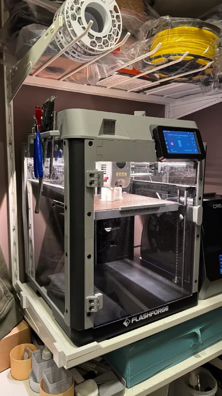
Following that I finished the top side, relocated the filament sensor, and attached one of Doug’s spool holders.
I didn’t install the drag chain, and frankly I’m not sure I will.
For Doug, some questions:
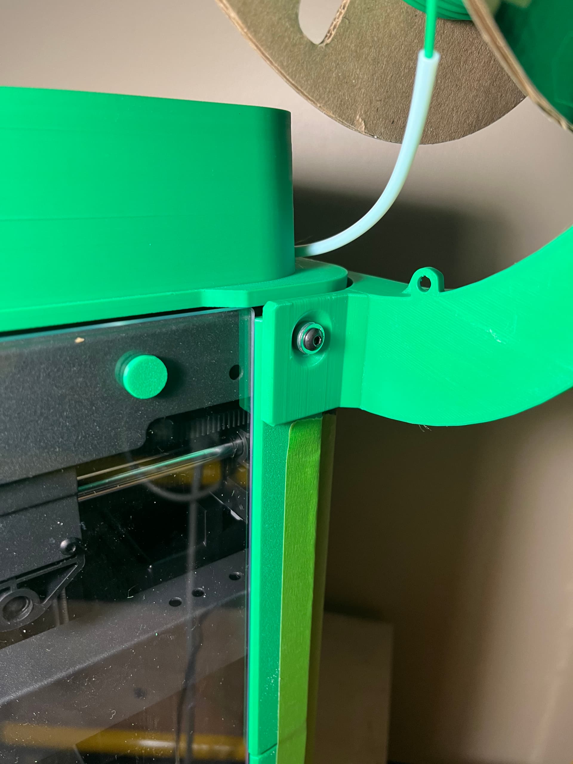
The M4 screw in the corner- what screw length did you use? It wasn’t one from the kit, right? This should be in your instructions. I found a random M4 and spaced it with some washers. I’ll find the right length tomorrow when I dig out my metric screw kit.
More questions:
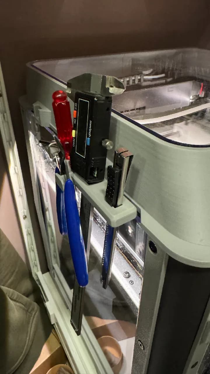
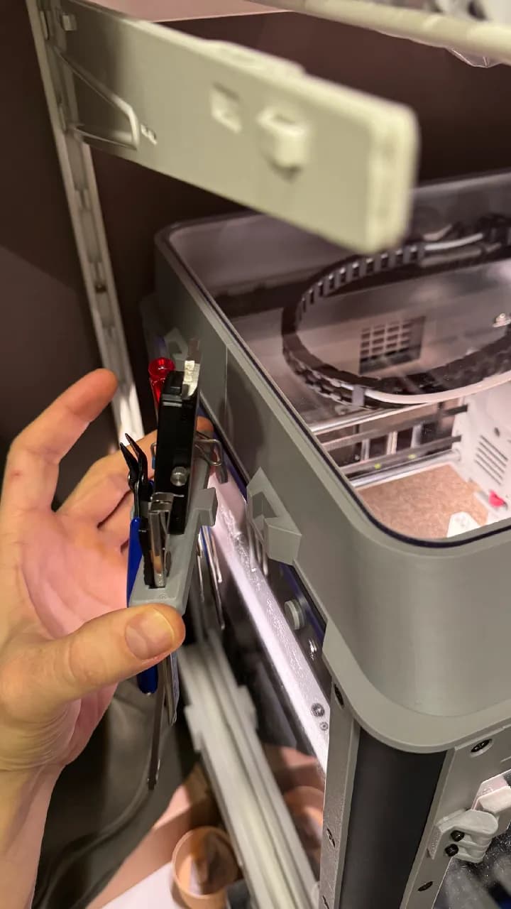
That spool holder’s nub for the PTFE tube can’t possibly be in the right spot. Note the angle in the picture above.
I ended up just leaving the PTFE tube free floating on this side and I don’t think I’m going to change it from that.
On my newest listing of the side mounted spool holder (v2.1), I have this in the description:
BOM
- Three (3) M3 nuts - one of these is in addition to the DIY enclosure kit.
- One (1) machine screw, M3 x 8mm - new in addition to the DIY enclosure kit.
- One (1) machine screw, M4 x 10 mm - new in addition to the DIY enclosure kit.
- Four (4) machine screws, either M3 x 5mm or M3 x 6mm. These would have either already been on hand from your existing machine and/or already were called for in your DIY enclosure kit or its BOM.
- You will also need the other screws from the DIY enclosure kit / or from your existing machine, for attaching the Filament Runout Sensor to the printed mount (I think those are two (2) M3 x 20mm), and for attaching the Drag Chain Fixing Clip to the mount (I think those are two (2) M3 x 25mm). If I have the length wrong on either, please let me know in comments. The stock screws that previously attached the Filament Runout Sensor to the metal frame, can be reused.
So, M4 x 10 mm.
And under INSTALLATION STEPS I have this:
- To attach the side mounted spool holder,
- First remove the top screw holding the printed guard plate from the DIY enclosure, at the back right side of the printer. This is an M4 screw, but it is too short to be reused. It will be replaced by an M4 x 10 mm.
- Hold the spool holder in place, and tighten the above mentioned M4 x 10 mm screw.
- At the back of the spool holder, shine a light into the M3 screw hole to make sure it is aligned with the screw hole on the printed mount, which has a captured M3 nut. The back of the guard plate itself is not attached in any way, and the torque from the screw on the side can cause the back to flex away from the frame slightly. You may need to exert a little force to press the guard plate and the spool holder, to get the screw holes in the spool holder and the printed mount to be aligned.
- Insert and tighten the M3 x 8mm screw attaching the back of the spool holder to the back of the wingtip on the printed mount.
So, it mentions M4 x 10 mm in both places. Is there somewhere else I should also add it?
OK. For now I just added the following on the minimal enclosure, in the section labelled INSTALLATION INFO:
In addition to the video and installation guide linked below, for the remixed side mounted spool holder, be sure to check out the BOM and installation tips on that listing here:
Later I can circle back and see if there is a concise way to include more.
Thanks for the feedback. Although I have used it for a long time in the location you see, I was thinking today about possible ways to do something higher and pointed up like you showed. I have not come up with it yet.
If I model up a taller, better approach, I’d try to make it backward compatible with earlier prints. Probably doable.
I’m currently using an older versuon of that holder, it might be the original one with the weird shape holder for the PTFE tubing.
For me it doesn’t come into play because I couldn’t get the short tube off of the runout sensor. I had meant to get my C clip pliers, but never actually did. Result is that there’s a short bit that barely sticks out the side of the enclosure to feed the filament, and sometimes it’s tough to get it past the sensor. That is part of what the new sensor is about, I gather.
Right now my filament sensor isn’t even bolted down, which is also inconvenjent…
But I’m printing the new enclosure now. That might get me to finally get the new top and front door cut.
I was giving serious consideration to an A5M Pro, and would have done it if the Black Friday “deal” wasn’t the same as the coupon thst was on Amazon before Black Friday. (Before, the price was $849 CAD with a $150 coupon. Black Friday special, $699. Current listing Regular $899, 22% off, $699.)
I had the same issue, and I think a lot of other people did — because Flashforge made a change to help with it. Quite a while before they made that change, my remixed spool holder + mount for the runout sensor, sought to better align the short tube with the runout sensor, to help with the difficulty. It seemed to help a good bit. Then Flashforge started shipping models with a newer version that is unidirectional. It’s described as making filament insertion easier. It requires being installed turned the opposite way from the old one, as far as the wire/cable is concerned. My third AD5M came with the new one. My latest spool holder + runout sensor mount adopts the new orientation. It’s indeed easier for filament insertion, at least for how I have it designed.
Well, I got the top parts printed, and installed them. I’m actually pretty happy with the spool holder, and in my case the back works better than the side, so I think I’ll leave that alone.
I do see that the reason I didn’t have the run-out sensor bolted down was that then the short PTFE tube on the sensoe wouldn’t reach the outside of the thicker wall, and as I said earlier, I didn’t get that part disconnected to replace it with a longer one. The new top parts look like they’ll be OK, so I might leave it still.
I don’t have the panel parts in place yet, though I think they’re all printed now.
The hinges I printed before work great. The new ones are totally fused. Both printed in PETG. The old ones were the ones from the official STLs, so with the smaller tolerances, and they’re very smooth, with full motion. The new ones, not so much, so although they’re bright red (And I printed the new stuff in starry blue) I think I’ll just use the old hinges. As an experiment though, I still have the files from when I printed them in red, I might try running the same file again. I think that will also print a door knob and a couple other bits, which will be extra. It will be interesting to see if it is just the filament that’s the difference. I have to assume that printing the same file will get the results as close as possible, though it was a different time of year, which means different ambient temperatures. (Actually, I don’t really remember when I printed that, it might have a date though.)
Doug
Putting the enclosure together now that my acrylic and hardware arrived.
Seems like the locations for the door hinges don’t alone with holes in the frame, so I can’t use the recommended bolts. What did you do on yours?