Because why not one more project?


My 3D printer was acting a little screwey. Turns out a plastic weld holding the Y nut broke, and the screw reinforcing the joint wasn’t quite tight enough to prevent some weird wobbles. That would be the strangeness in the text of the V1 logo on the case cover I printed last week.

Well, I re-tightened the screw, so it’s good now, but I’ll need to do some more major surgery to redo the plastic weld. In the meantime, I thought I’d give the MP3DP a go. I still have most of the pieces from my first I3, which was an abysmal POS from the word “go” but it did get me started in 3D printing. When complete, this will live in the basement shop, so that I won’t have to run from basement to attic. This will probably also be more or less limited to printing PLA since the spare heated bed I have is 12V only.

I’ll use the MKS Gen L v1.0 that I pulled off of the Primo for control, which will also give me the LCD for headless control.

The biggest cost to build for me is the plywood thst I’ll be making the frame from. Second will be the red PETg that I’m printing the parts with. I’m reasonably sure I have everything else already, we’ll see.

4 Likes


Had a bit of a mishap. Cutting the XZ frame, I hit a clamp with the Z tube on the Primo, skipped some steps and it ain’t right, so looks like I’ll need another piece of plywood. The Y frames, front and back came out nice though.

Well, gotta go pick up screws and so forth anyway. I’ll find another use for the non bjorked part of the plywood I’m sure, or something where I don’t care if it’s got a gouge in it.

About 20 minutes until the X axis parts finish printing.

Decisions to make. I have a Bowden extruder, and the stuff to do the tube to an E3D V6 style hotend. I’ve always done direct mounted hotends before. I understand the advantage of the Bowden remote is lower moving mass, the drawback is … ? More pressure advance? Retraction? Not sure… it’s more parts to assemble, but I have them.

Maybe I’ll try it. I might like it. I guess that means figuring out the hotend stuff soon.

I have an IR height sensor that I plan to use for Z probe. Still waffling on 12V or 24V operation. My I3 was 12V, everything after has been 24, but I still have the 12V PSU, and several 12V cartridge heaters for the hotend, might be a good use for them.

2 Likes

With a bowden setup you’ll have a rough time printing anything soft like TPU. 1.75mm TPU is like spaghetti. I have a sample roll of ninjaflex and even on my MK8 it keeps creeping out of the 2mm gap between my extruder gear and the throat. Sheesh! You will also want to set your retraction distance a little longer. The tube on my one printer is 21" long and I use a 4mm retraction setting.

Meh, I’ll go with a direct drive extruder, because the parts already are there to support it. I’ve never printed with TPU before, and am not sure that I’m going to start now.

What I am going to do though is a small remix of 4 parts. The object of the exercise is to change frm the 16T idlers and pulleys to 20T ilders and pulleys. 2 main reasons for this are:

  1. I HAVE plenty of spare 20T idlers and pulleys, because they come with things like GT2 belt kits, and by accidentally ordering them for things like my ZenXY, or in one case, because that’s what I was shipped even though I ordered the correct ones, and they didn’t ask me to ship them back.

  2. The bearings on the 20T idlers are much better than the ones on the 16T idlers. The 20T idlers have a 5mm bore, where the 16T idlers have a 3mm bore. The smaller bore bearings are finer, and less tolerant. They don’t last as long and are more prone to damage from having the belts tightened, being overall weaker.

This increases the unique part count by changing out some 3mm screws for 5mm ones, and associated locknuts, but I believe lowers the overall cost. Well, to me it will at least.

There are 4 parts that I need to change.

The Y block needs the belt pathway raised by 1.27mm. The info that I have shows a 16T idler as having a 9.68mm diameter, and a 20T idler as 12.22mm for a difference of 2.54mm, or 1.27mm radius, based on the pulley dimensions. Therefore in order to keep the pulley from having a parallax error, the belt pathway needs to be moved by that 1.27mm.

The X carriage needs a similar modification for the same reason. I will also consider changing the belt tension to the same mechanism as the Y, with sip ties opposite a pass-through belt attachment.

The XZ end piece and the Y bearing block need the holes and bearing stand-offs enlarged to accomodate the 5mm screws for the larger idlers.

Based on the 1/2" plywood that I’m making parts from, I got 1.25" #6-32 screws, as being slightly longer than the 1" recommended for the 3/8" I didn’t read close enough, because 1" is totally fine for the 1/2" plywood, and sure enough the build docs say so. I know I have a bunch of 1" #6-32 screws, but I don’t know if there are enough. If not, I’ll need some more. I don’t like having that much extra exposed thread.

Anyway, there’s my evening remixing parts, and re-printing the ones that need modification.

20T mods.zip (182.7 KB)

This is a quick TinkerCAD edit. I imported the published .STL files into TinkerCAD, and fiddled with them until I was sure that I had the 3mm hole centers within 0.1mm, then put a 5.1mm cylinder hole through them. Because of the way TinkerCAD does cylinders, this might still be a tad undersized. I SHOULD have increased the pad size inside the holes, too, but didn’t yet. I might do that later, but this is just to have something to print tonight.

For the belt loops in the Y block and the X Carriage, I used the subtract function to make a negative image of the belt grip, then superimposed a solid version of the same in the exact same place to fill the old gap, moved it over 1.27mm and superimposed a cutout version. I used a similar trick to remove the cable tie point from the X carriage to try moving the cable tie to the belt on the opposite side from the carriage. If it doesn’t work out, then I can go back and “ungroup” that last bit. Not sure that I need to move the cable tie point by the same 1.27mm, but if I put it back, I’ll probably do that. I’m going to try it this way though.

Feel free to grab this .zip file if you like. So far, I’ve just sliced them, and they look OK. We’ll see how they print.

2 Likes


New parts, still warm off the printer.

Y Block. Belt path brought 1.27mm closer to the base to accommodate larger 20T pulleys and idlers


Y Pulley block. Hole enlarged to 5mm to allow larger bearings. I could PROBABLY have just printed a tube ID 3mm OD 5mm and stuffed it in, actually… but I had to change stuff, and I have spare 5mm screws.


XZ End. Hole enlarged, blah blah blah. This seemed to have a more robust pad inside, it should be pretty good.


X carriage. This is the most drastic change. The important change is moving the belt clip 1.27mm closer to the X rail. I also removed the zip tie clamp though. It looks to me as though there is enough room there to let a little zip tied lump pass back and forth without causing trouble. I DID leave an undo on that part though, so I can put the zip tie clamp back if it does cause problems. I should probably print that version in the same filament before I use it up… backup plans…

Home Despot had no 1/2" plywood, except the oak stuff that costs a small fortune. I do have some birch left over from the Primo torsion box, but it won’t match. Maybe I’ll do all of the milled pieces over, and re-do the XZ frame later when HD has stock again. I was planning on giving a 3D printer to my son for his upcoming birthday. I’ll turn it into a kit.

Aaaaaaand the verdict is…

NG!


I need to re-do these 2 pieces, as the 20T idlers won’t fit in the provided space.

Well, I don’t have any toothed 16T idlers, but I have smooth ones, and I have the 16T 6mm pulleys from my ZenXY, so maybe I’ll just build it that way, and come back to those 2 pieces later. Or the idlers are aluminum. I could grind the flanges down by a mm or so. Maybe I’ll go that route. Tomorrow.

1 Like

Grind them! Just make sure to really smooth the edges as the belts will wear superfast.

Then again a minor mod on two parts and reprinting would probably take the same amount of time.

1 Like

So…

These pulleys are constructed a little differently than I thought. Makes perfect sense, in retrospect.

I thought that the pieces would either be a solid cast, or at least brazed.

Nope. The flanges on the end are just pressed on, so as soon as I hit them with the Dremmel, and the flanges warmed up enough to expand, they popped right off.

Good news is that makes them very easy to modify. Bad news… they look like this:

One had the flanges ground and heated, the other, I just clipped with side cutters. Identical results.

But I think they’re usable this way. I guess it depends on if the belts tend to walk. I can print something to keep the belts centered easily enough. I guess I’ll just try it this way.


Found another piece that needs modification… the X motor cover won’t fit over the larger pulley.


If I use zip ties to hold the ends of the belt, it risks getting snagged by the carriage. Heat shrink tube works great and doesn’t snag at all, the final zip tie to tension the belt doesn’t cause a problem.

The 1.27mm shift appears to be perfect. The belt is as parallel to the top rail as I am able to measure with my calipers. No measurable variation in distance across the span for the tip belt at all. The bottom one wobbles near the joint, but that shouldn’t matter at all to the print head position.

5 Likes

That heat shrink idea looks great too.

3 Likes

I’m kind of proud of the heat shrink idea. I was just about set to re-print a carriage with the zip tie mount, or maybe add a loop just past the pinch point when it hit me that all I really need to do is force the belt ends together and not let them come apart. The heat shrink also doesn’t pinch the belt into a round shape, but really doesn’t let it come open in the slightest. I’m betting that I’d destroy the bearings in the idler or the stepper, or at least hopelessly stretch the belt before they let go, and since I have no plans to tension anything that tight, should be fine for the life of the printer.

I left a little more “tag” end on the zip tie, so that I can let it out a notch, or tighten it more when I have the rest of the rods in place. I’ll trim it much closer to flush when I’ve got the Z width fine-tuned.

I re-printed the X Cap part, so now there are 5 parts that need to be updated to allow the 20T pulleys and idlers. I’ll update that .zip file afterwards, in case I come up with more “gotchas” assembling the Y axis.

I was sure that I had 2 of the 250mm 8mm Z leadscrews, but I can only find 1. I do have plenty of regular 8mm all-thread at 1.25mm pitch. I could print a nut holder for that that would fit the gantry to keep costs down. I need to adjust all the steps/mm anyway with the 20T pulleys.

1 Like

I went to the shop to finish cutting LowRider Y plates…


Instead of grabbing the 1/2" MDF, I grabbed some subfloor that I had, and made some printer parts. I measured diagonals to be sure I had the CNC square, and it’s as close as I’m going to see with the tape measure, which makes me happy.

I have some 5/8" screws that I’m using to attach the bottom plate, I’ll make up a set of plastic feet to go under the printer, maybe I’ll check a Dollar store for some rubber ones that I can make do the job. I suppose I really only need 4, will probably do 6.

Gotta try a different Home Despot for 1/2" plywood to make the XZ frame. I know it’ll bother me to no end if the wood doesn’t match, so don’t want to make just the one piece from the birch.

Waiting for some LM8UU bearings for the bed slide, and I need the Z smooth rods apparently. I was sure I had spares… right next to the leadscrews… looks like a week delivery time from Amazon. I also thought I had more left of the rods that I used to cut those Y rods from

Starting to be a little more expensive a project than I had hoped for.

A couple other little touches to order. A print cooling fan maybe. I need to decide on 12 or 24V before that. I have both supplies already, and the MKS board is happy with either.

My order of #6-32 nylock nuts came in today, and was a box of 3/8" split lockwashers. Gotta send those back…

1 Like

Success! The third HD I tried had one piece of regular 1/2" G1S plywood.


Cut the XZ frame and attached. Now I’m stuck until my LM8UU bearings and the 320mm smooth rod arrives. Well, I suppose I can start with the wiring, install the Y motor and sth. I’ll have to remove the bottom plate to do that, of course.

I don’t have countersink screws, so I made feet to cover the screw heads.


I consider it an exercise in learning to use the lofting tool in FreeCAD. Nothing too fancy, just a slightly conical hexagon, with a circular pocket for the screw head.

The X motor in there is only temporary, it’s a damaged one I use for sizing. I have 5 good motors for X, Y, Z, Z, and E that I can use.

What I’m missing at this point is 3 LM8UU bearings, 2 320mm smooth rods, and hot bed mounting screws and springs. I should check a few more parts boxes though.

2 Likes

Thanks for the heat shrink idea, I just changed the dimensions on my MPCNC and was going to buy more zip ties, but I have tons of heat shrink!

1 Like

So… This is what you get when you rush into something headlong…

I hadn’t realized that you don’t need all the holes in the Y frames. Again, perfectly obvious when reading the documentation. Well, they won’t hurt anything at the very least. The problem comes with the fact that I’m using a different control board, which of course mounts differently. Good news is I’m pretty sure that my PSU will mount in exactly the same way, so at least I won’t be needing extra holes on both sides.

Oh, and found another “gotcha” with the 20T idlers. The bolt that goes through the X end has to have the nut side towards the front. Putting it the other way, and the locknut is a little too thick, and will contact the XZ frame (Or rather, any part of the bolt that sticks out past the locknut.) I tried cutting the bolt to just the right length, which is probably a good idea anyway, but having the nut to the front seems to be the best option.

Waiting on Amazon parts. 330mm smooth rods. (If I ordered the 320mm that I need for the uprights, they’d take until next weekend, but 330mm rods will be here today. I figure I can live with 10mm sticking out the top, or if it does bother me, I can cut them.) 300mm leadscrews (Now I remember what happened, and why I can only find one of the ones that I was sure I had. I used the other one for the Z axis in my Primo.) the LM8UU bearings, and I’ve run out of 2 conductor wire for the stop switches.

I get the distinct feeling that I’m going to want to implement dual Z endstops for homing the machine. It’s just such a pain when the motors power down and the X carriage is no longer level to the bed. I think I’ll see if I can figure out a way to use optical stops for it. I have no intention of using a second extruder, so I could use the E1 drive, same as on my current printer.

Made an “oops” with the bed mounting. I have 3 springs, but the heated beds that I have need 4 screws to mount. It just didn’t even occur to me that these wouldn’t support 3 hole mounting. I looked at my current printer and sure enough, it’s mounted with 4 screws on that one, too. Seems a waste to make a trip to Home Despot for a $0.42 spring. Well, I’ll search for an alternative. Maybe I’ll make a solid spacer for one reference corner and adjust the other 3 corners to be equal to it. A few washers should do the trick, or I can mill one. I’d rather not 3D print it, the heated bed shouldn’t get hot enough to deform it, but why take the chance?

I’ve been messing with the firmware, to see if I can implement dual endstop homing. I think I’ve got it sussed, now the problem is going to be setting up the physical endstops.

Ryan’s parts are of course configured for the NC switches. I’m going to have to retrofit something. It would be nice to be able to mirror the left side mounts, but there are a couple of reasons why that isn’t a good plan, not the least of which is getting a wiring solution to the right side X end.

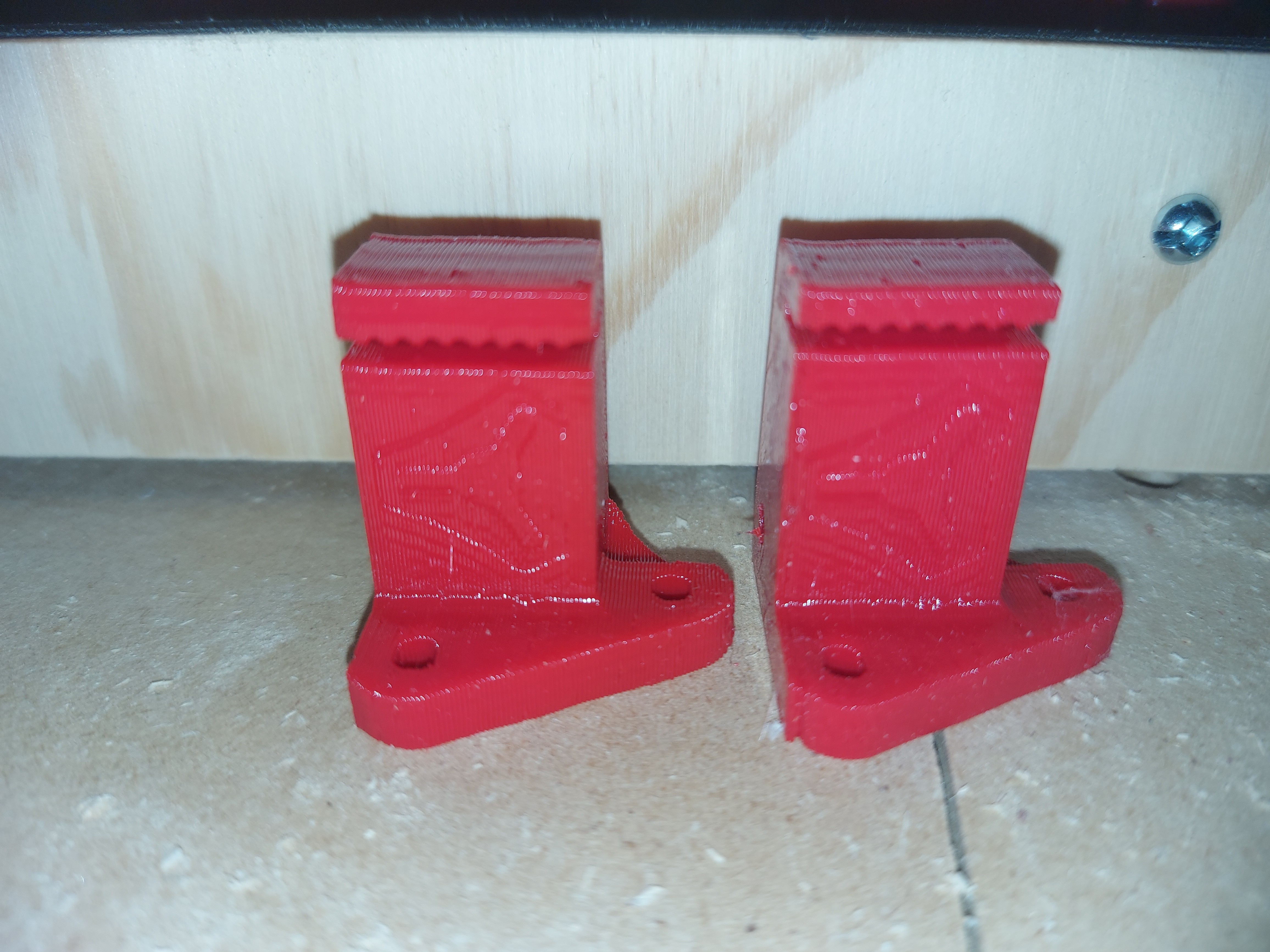
So the idea will be to add flags to the X ends, and mount optical stops to the Z motor mounts. The trick will be the adjustability. Since this is going to determine the Z=0 height, and it needs to be precise, there has to be some fine adjustability available. I may end up stuck with the kind of solution that I usually dislike.

“I have some of these unusual and sometimes very difficult-to-get parts, so I’ll use them.”

I dislike it as a solution, because it’s not something that just anyone can use.


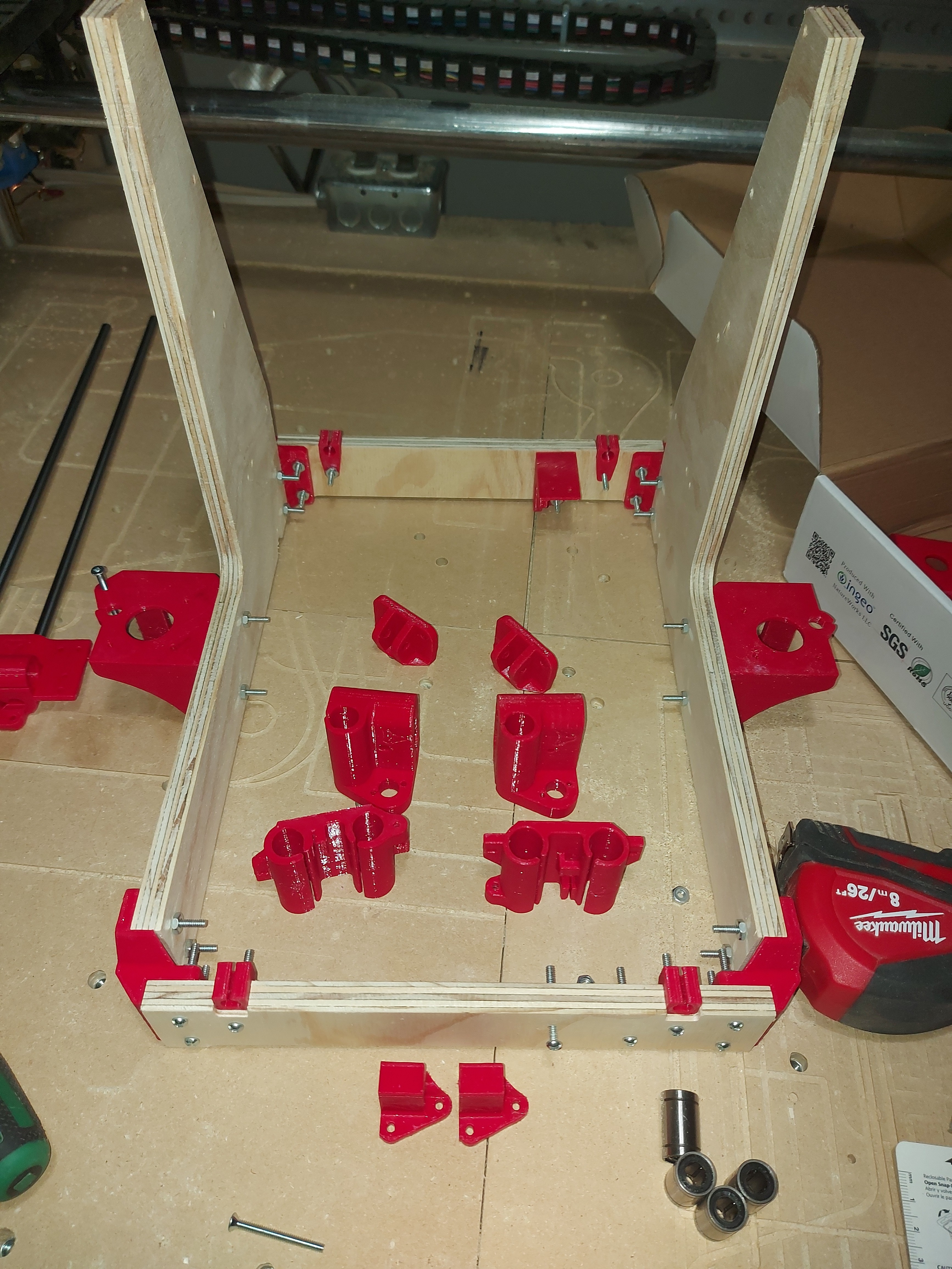
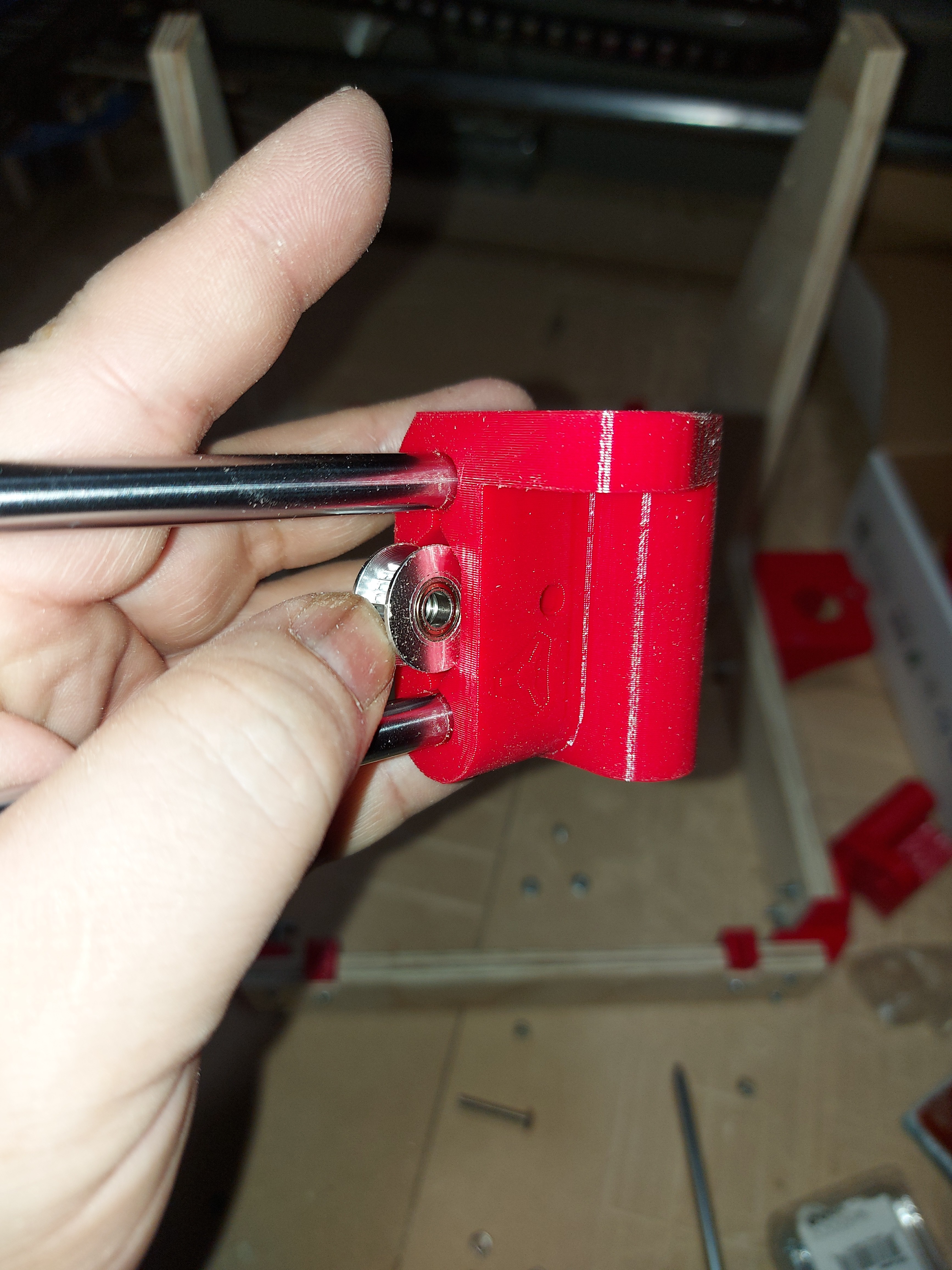
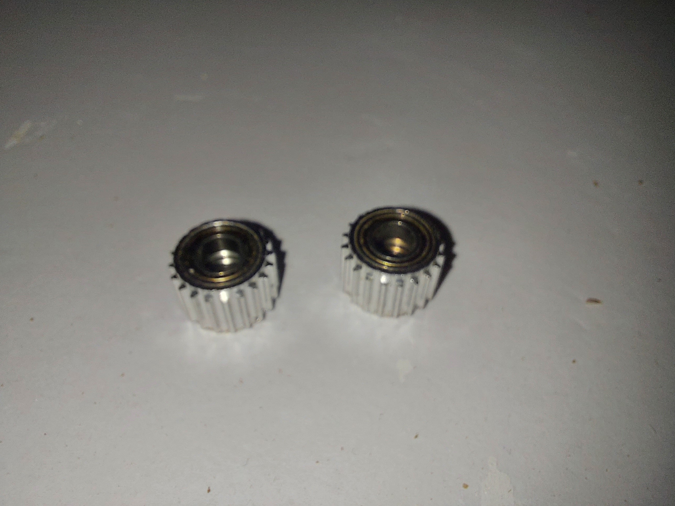
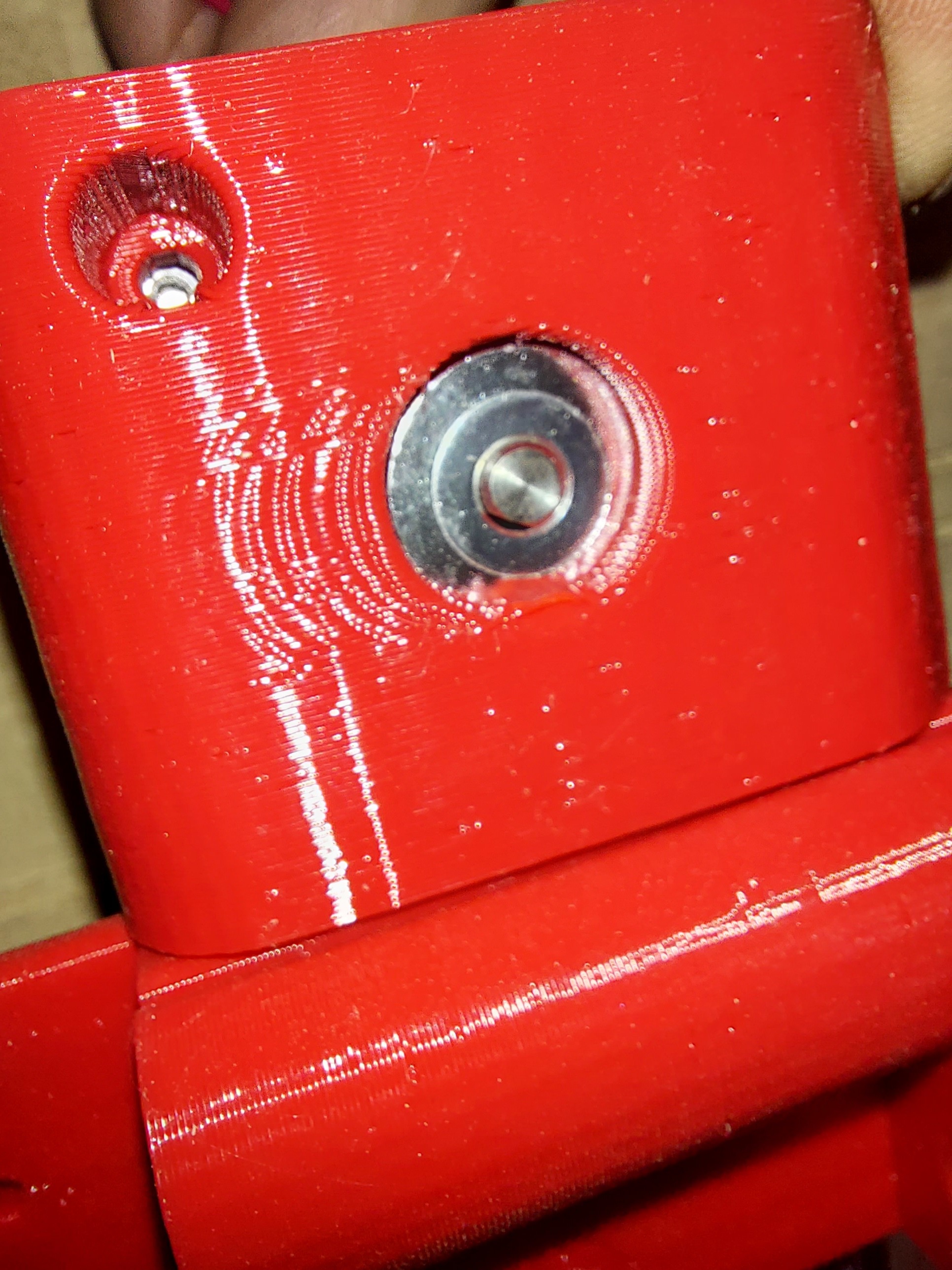
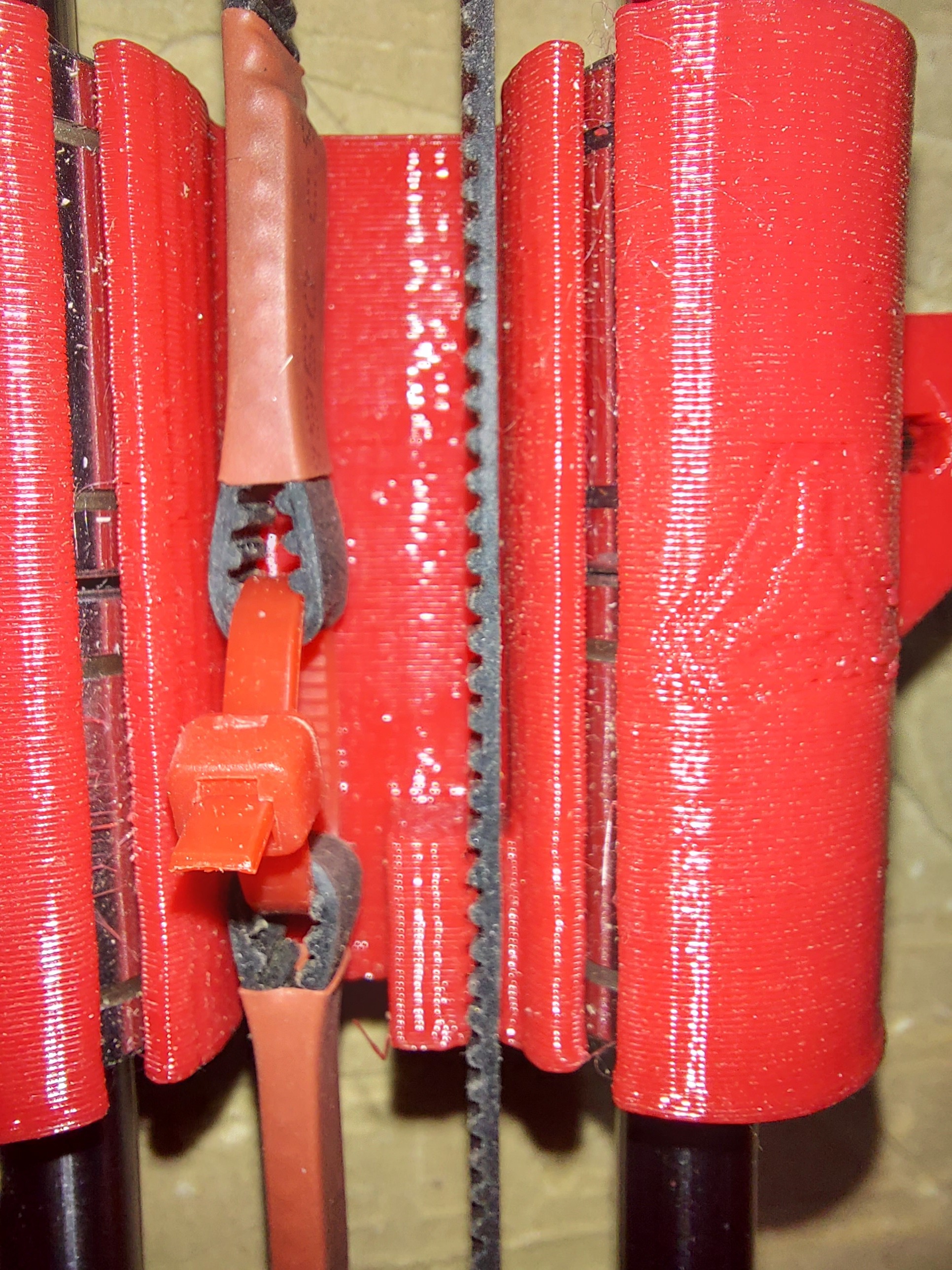
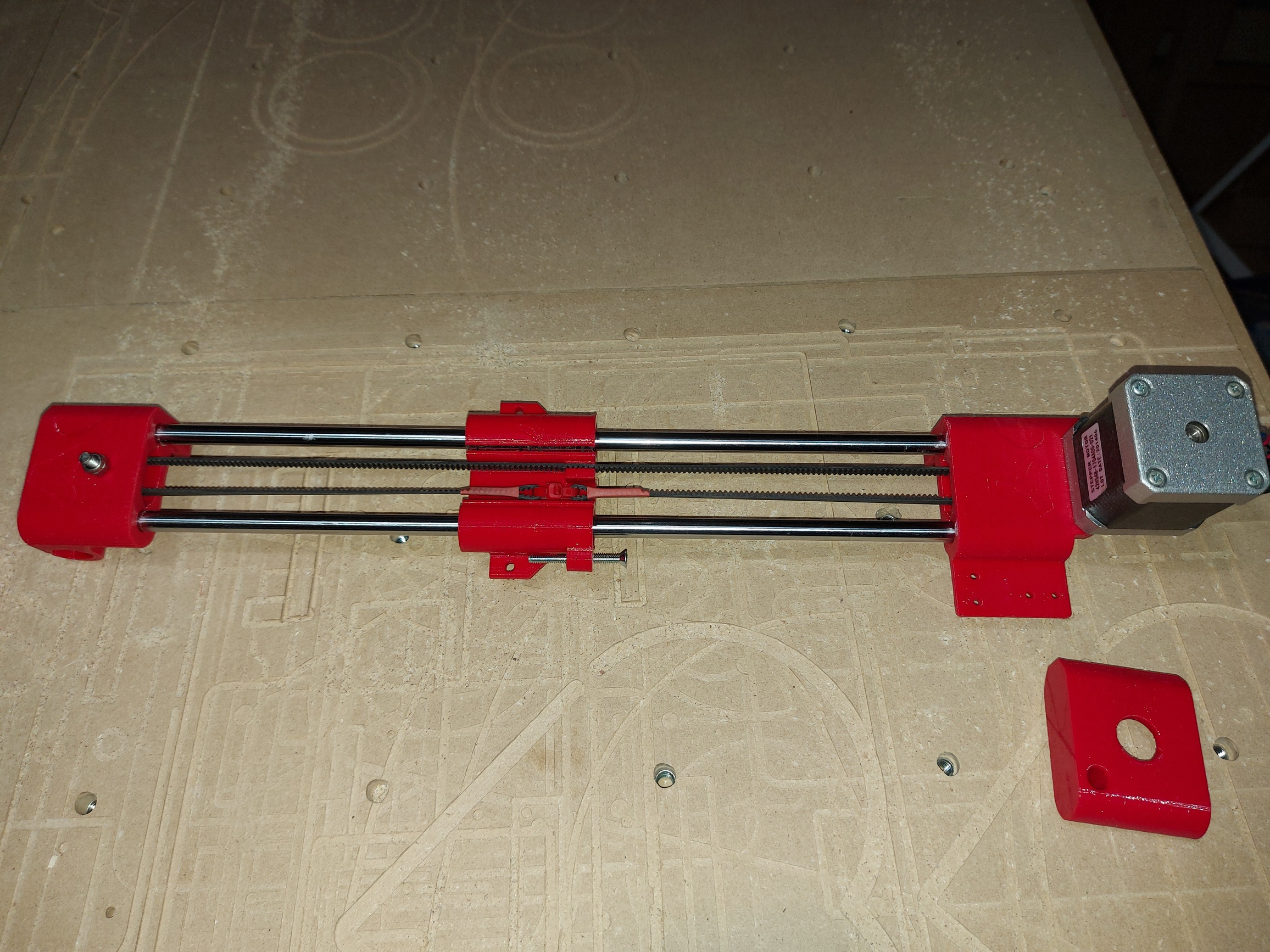
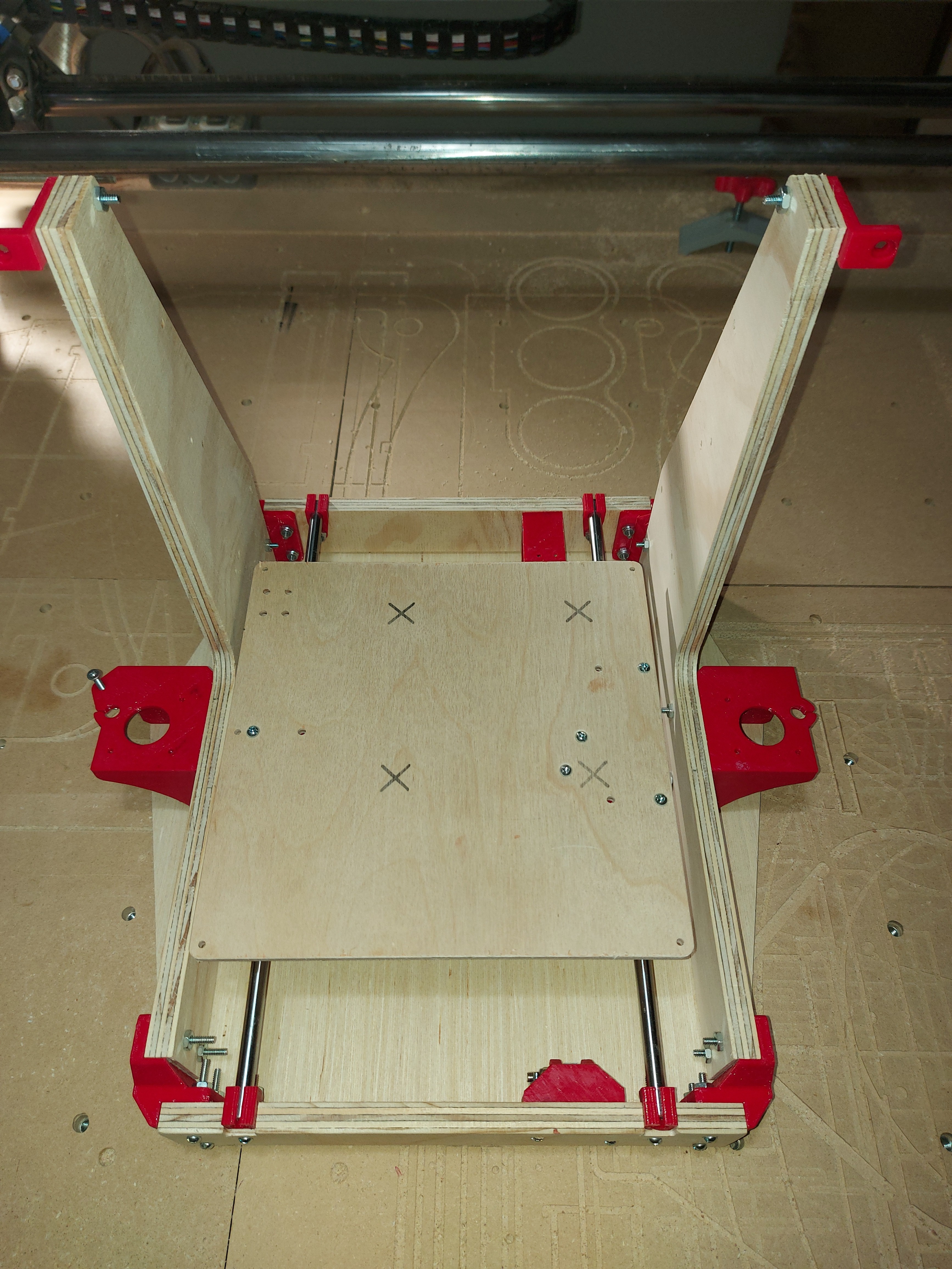
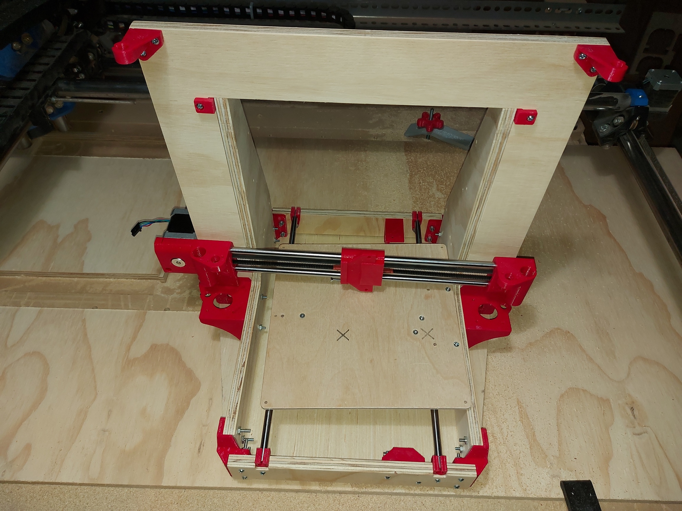
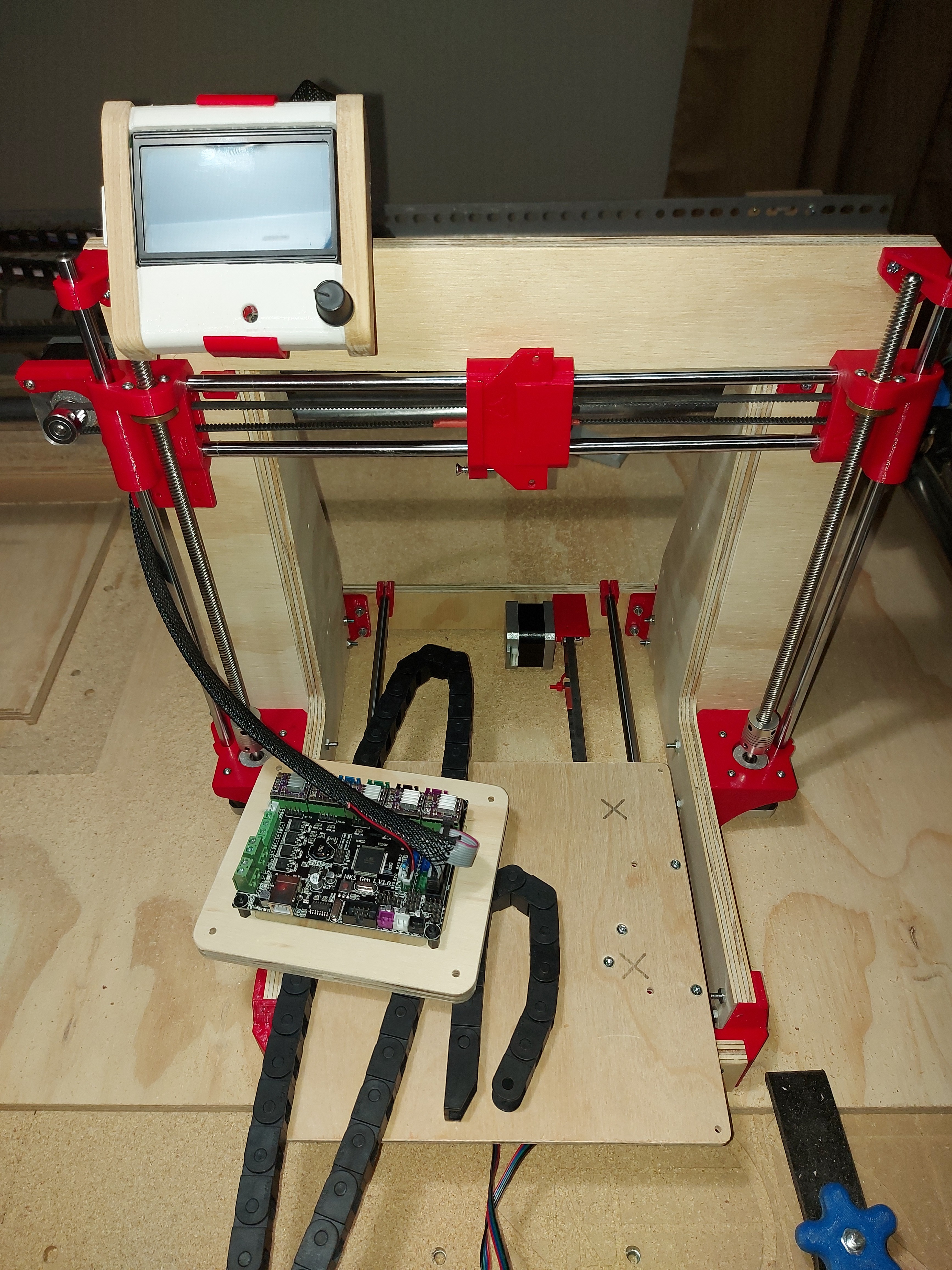
Anyhow, this is the current state of things. I took the bottom off to install the Y motor and belt. There are a couple of spacers in the Y bearing clamps to keep the rods centered for testing, and so I can figure out the placement of drag chains for the heat bed. So tired of things snagging a wire and unplugging something.

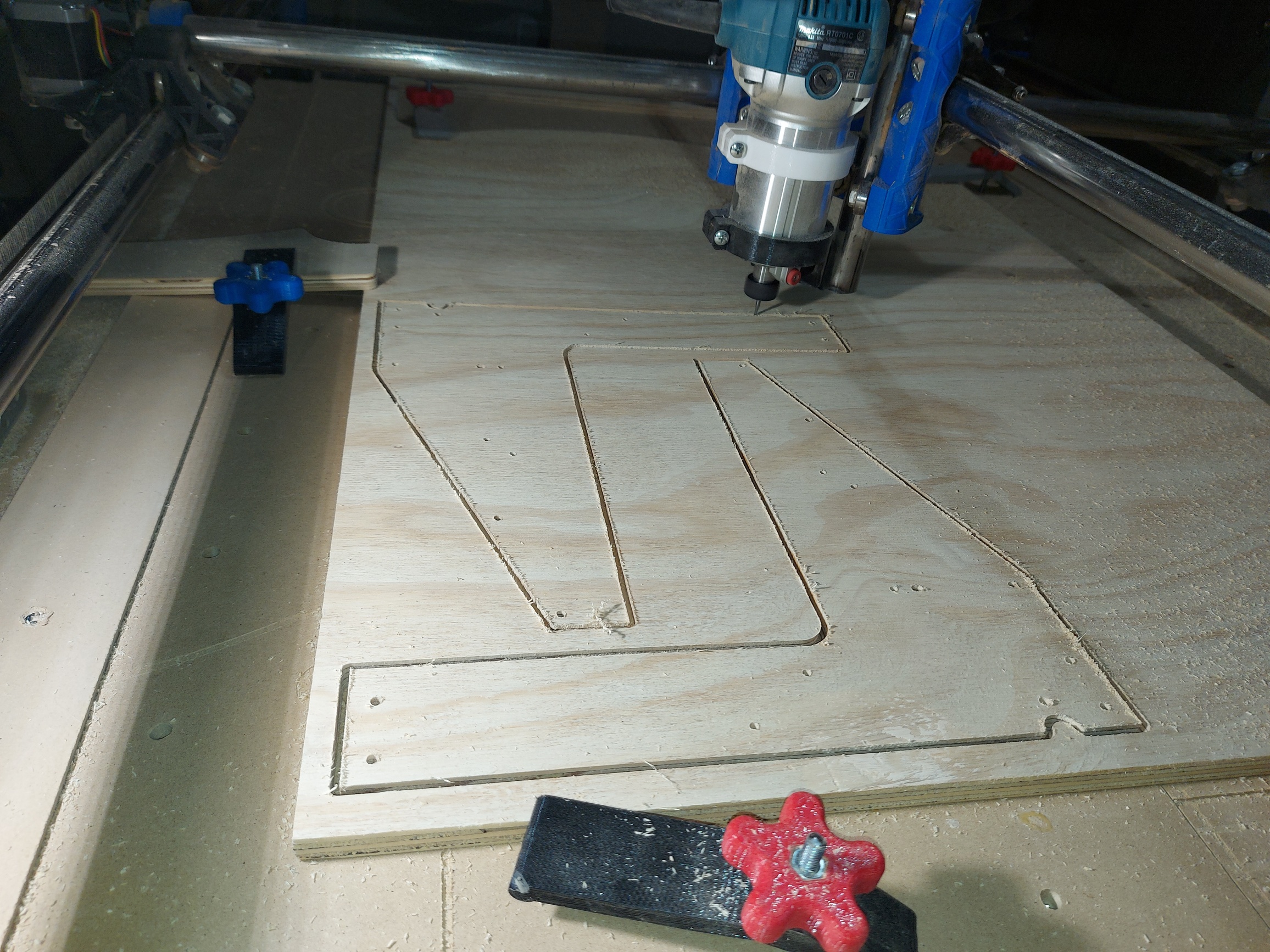
I re-mixed the LCD holder to clamp onto the XZ frame, and milled a baseboard for the MKS Gen L v1.0 board. It has a 1/8" pocket under the board, so I could just screw it directly down with #6 PC case screws, which will make things easy. I did a printed case cover in CAD, but want to see what I need as far as cable accommodation before I actually print it, particularly since I don’t know what I’m doing about the Z endstops.

I did have an idea, put optical stops in at the top to level the Z motors, and use a probe to find Z=0, but I have no idea how to do that with Marlin. I could do it with RRF on the Duet easily enough, and now that I’ve thought of it, I might on my current printer.

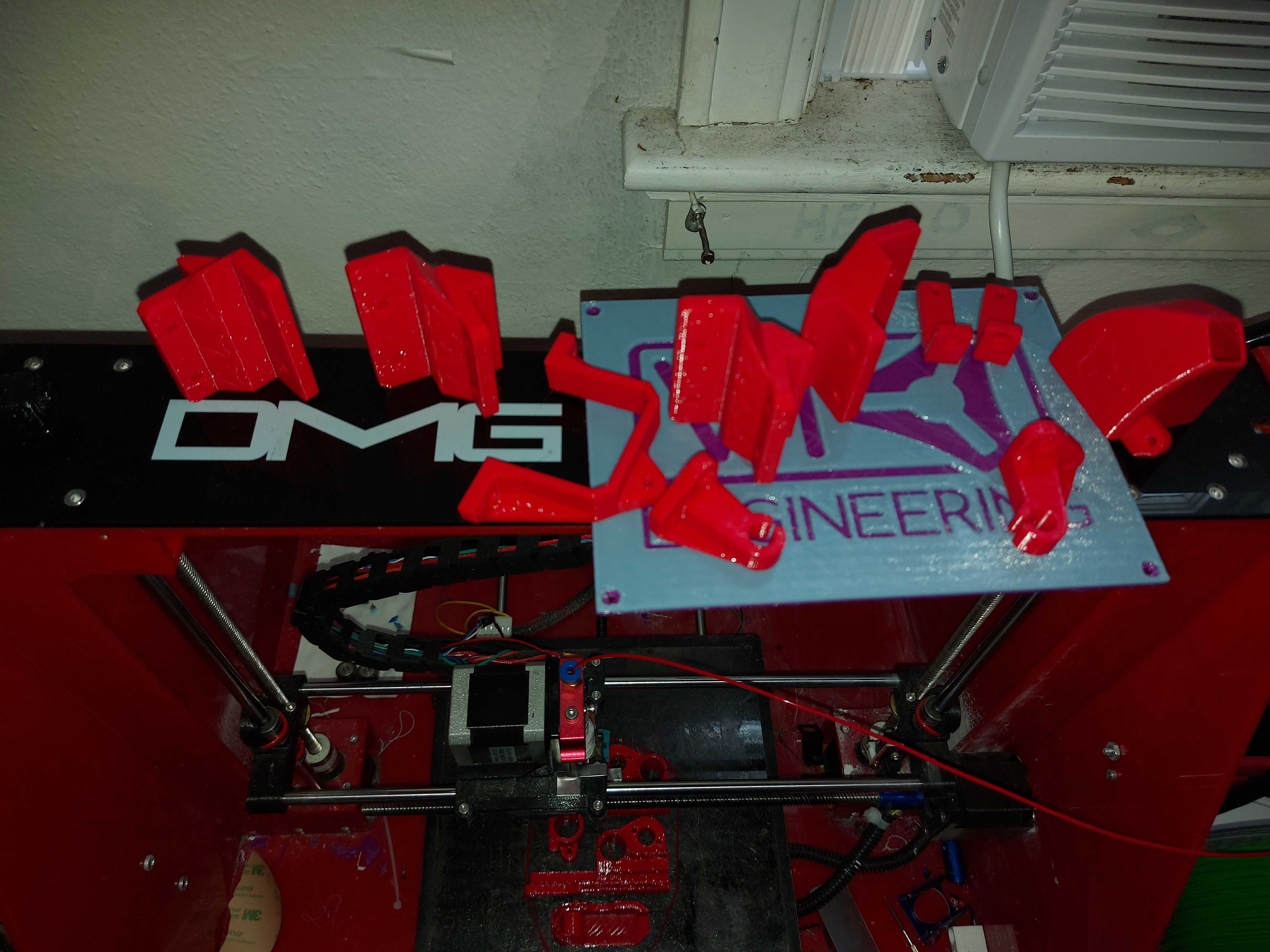
Looks like I need a few more pieces, something for a power cord plug in, and I think I’m going to go with a Bowden style extruder after all, so I need pieces to mount an E3D V6 Jhead to the carriage.

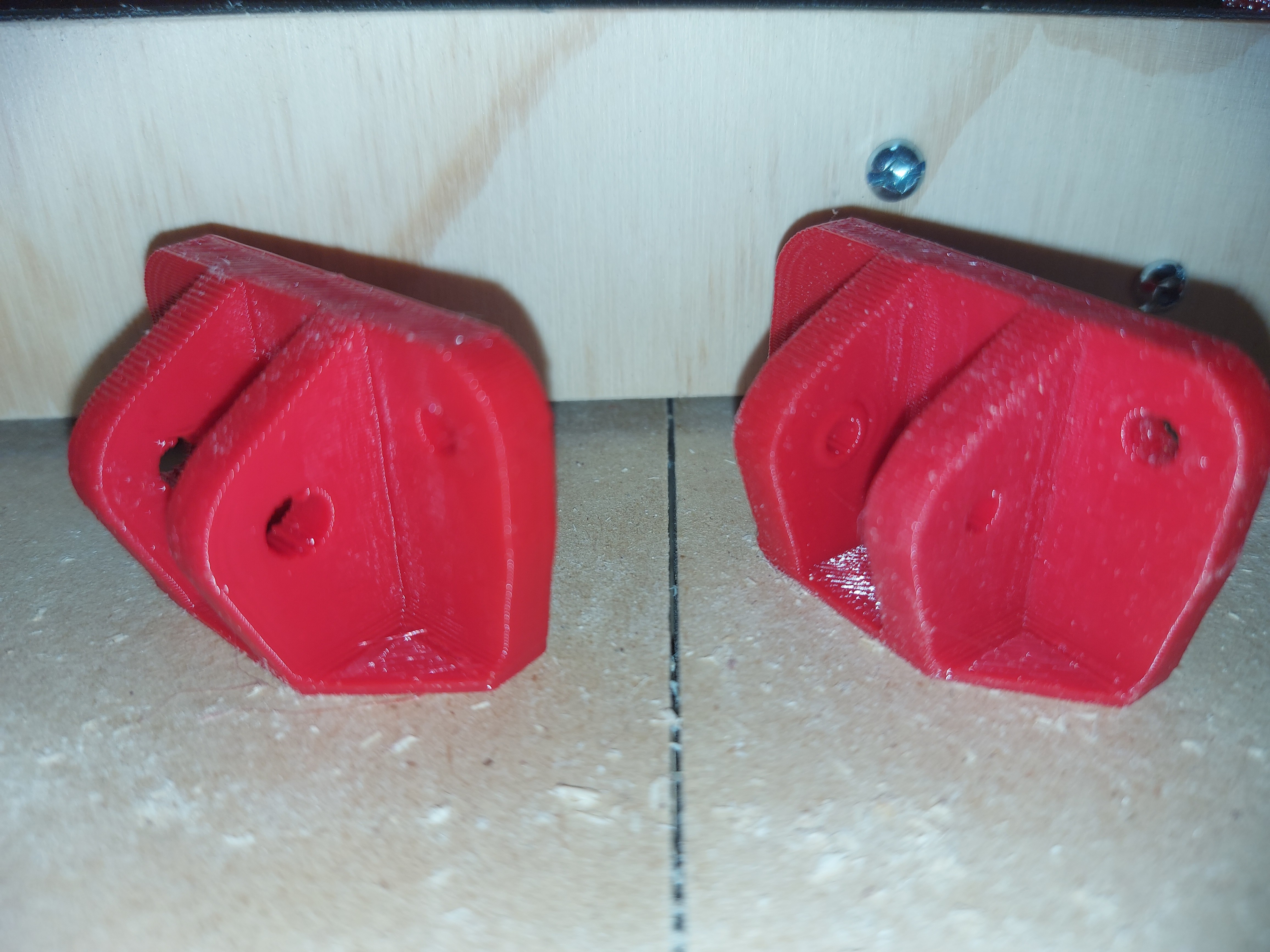
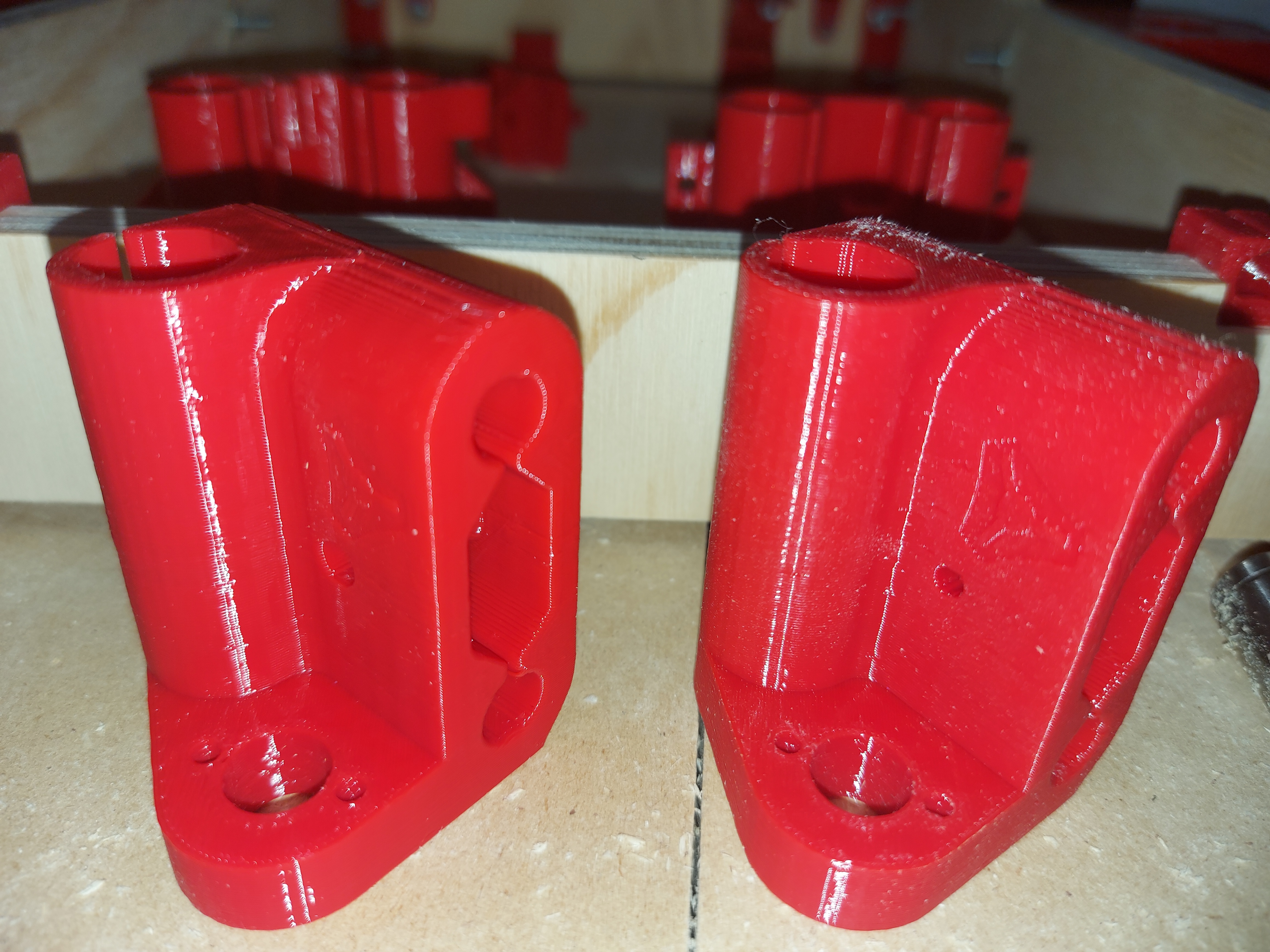
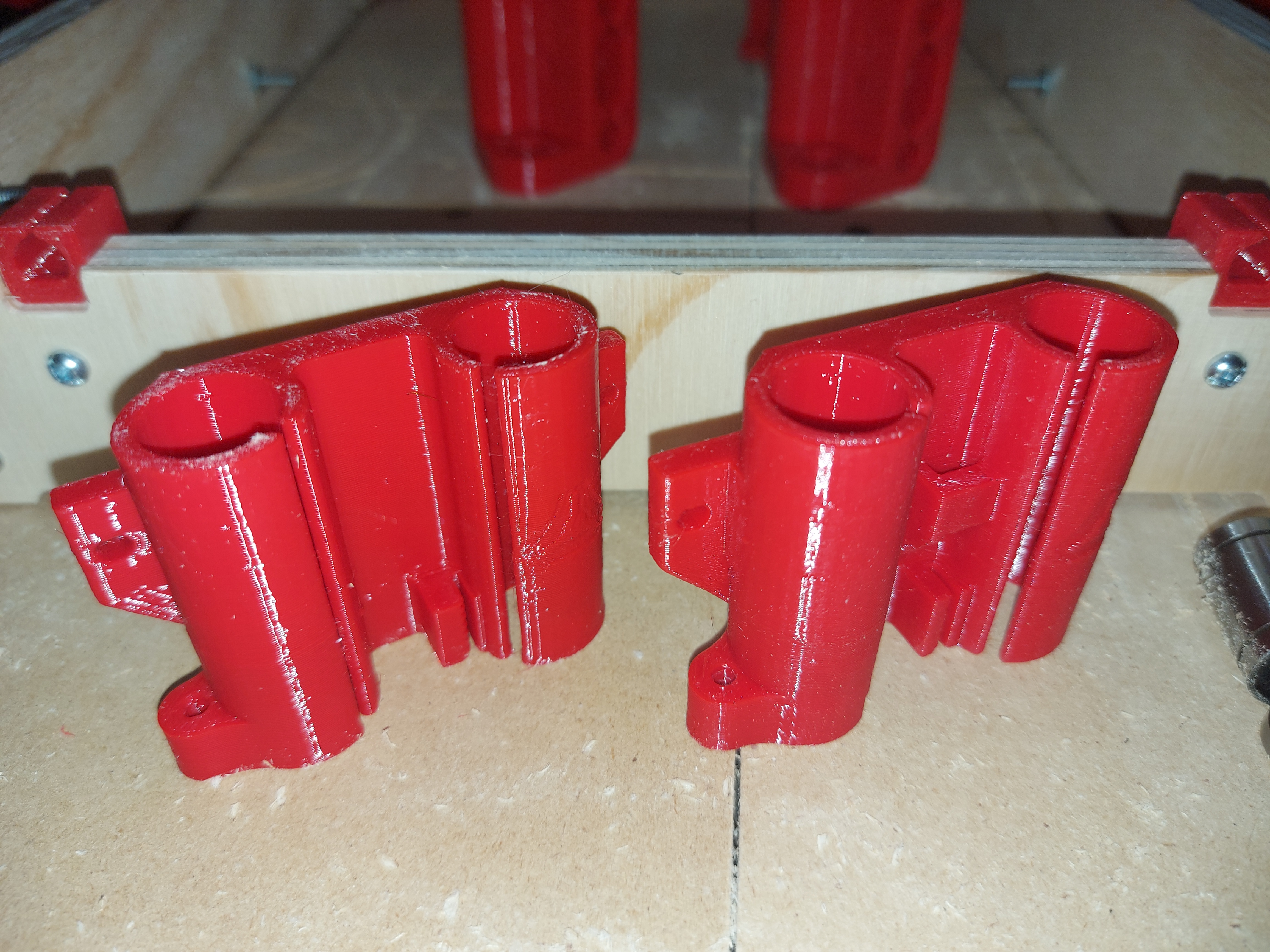
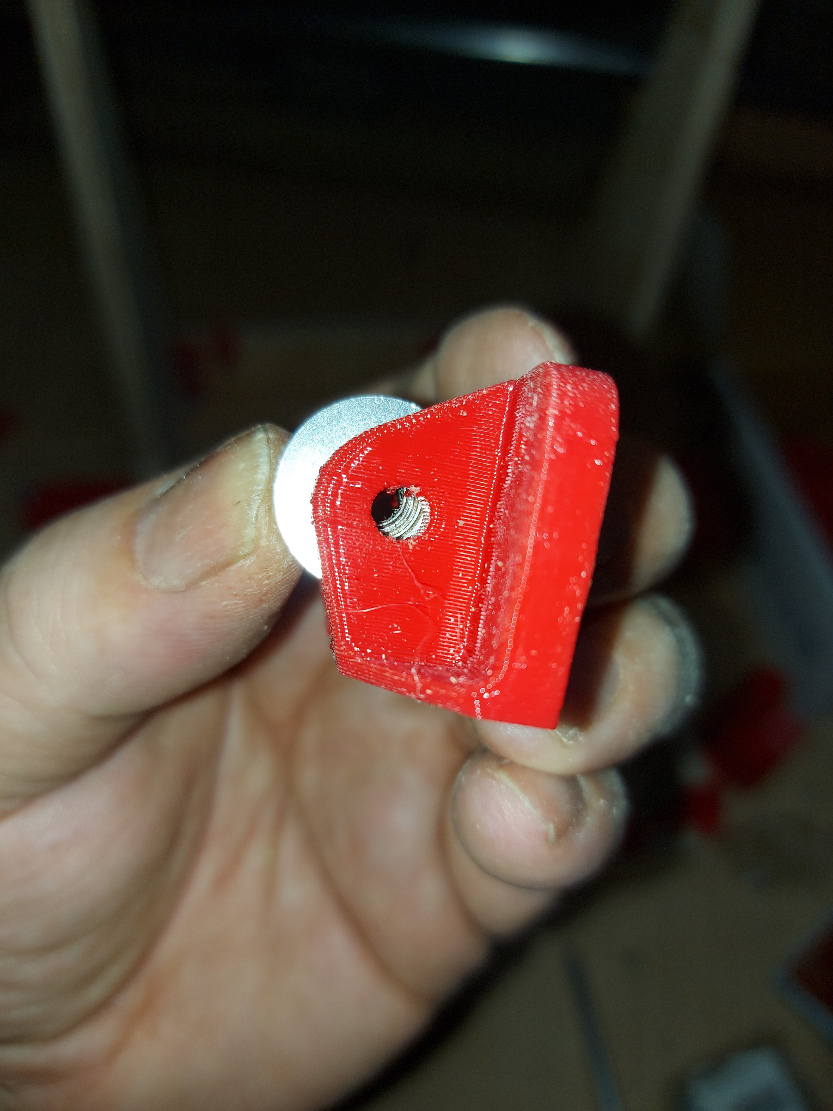
My spool of filament arrived, and I messed up. It’s a transparent red, so it won’t match right. Looks really cool though. I can either live with a mismatch, or just plan to replace anything I print for it in the next few days.

I noticed something a little weird. The Y platform does not sit centered in the frame. It is about 1/8" closer to the left frame than the right. I don’t think this will cause problems though. I believe the bearing holders are centered between the mounting holes, and the belt holder is perfectly in line with the idler and pulley. I just thought it was a little weird.

It isn’t too bad to add a bltouch and enable bilinear mesh leveling. If the gantry isn’t level, it will just fix it while printing.

With optical endstops it doesn’t matter you can use a positive or negative offset.

The extruder travel and position are not symmetrical…or centered. For most direct drive extruders the platform allows for full work area use. That means some things are offset a bit.

1 Like

Yeah, I figured out the extruder travel pretty quick afterwards.

I don’t know enough about Marlin for configuring those endstops. Nor enough about the mesh levelling.

On my Duet machine, I have a macro (Basically just a Gcode file) that probes the bed on the left and the right, and turns the motors to ensure that they’re level with respect to the bed. It also has a mesh level function, but I don’t use it.

So this becomes another potential solution, to try something similar. Use a probe on the hotend. The mesh levelling will probably do the job just fine. I have an IR sensor that I can use, and it already has a hotend mounting solution, so that part of it at least is fine.

I should probably just take this as an opportunity to learn more about Marlin setup. I really like the idea of the dual endstops, and if it’s a “simple” matter of defining offsets, then it shouldn’t be too difficult to get them set up nicely and reasonably permanently. A static mount for the offsets and flag are much simpler problems to solve, then it’s just software.

For me it depends on my mood. Typically, I prefer to solve things with hardware. Once in a while though, learning some new features can be fun.