Its looking great!
3 Likes
IT’S ALIVE…
Powered it up and ran it through some initial movements. I had a couple of issues:
Several of the motors were wired backwards, so I had to flip the connectors (no big deal, somewhat expected)
When I sent the first Z command to move 1 mm down (Z-), the Z2 (rail side) motor zoomed all the way to the top (wired backwards explains the direction, , but the runaway is still a mystery). I had to scramble to unplug it quickly. On that movement, the Z1 motor either only moved 1mm, or didn’t move at all.
I had another time where both Z1 and Z2 crashed again (at least in the right direction this time), and several attempts where any Z movement responded with “Error: Print Halted - Kill Issued” message. I also had a weird issue where commands to any of the motors (X, Y or Z) from the LCD screen would only allow a single movement +/- from starting position (if set to 1mm, it would move from 0 to +1, and then back to 0 and -1, but would not move to + or - 2).
I unplugged everything again, checked all of the wires, and discovered that the Z1 wires were misaligned, and only connecting to 3 pins (photo is an example, it was actually the Z1 pins).

Once I corrected that, everything seems to be working great. I can home on all three axis, all of the endstop switches (including the touch plate) appear to be functioning properly (all LEDs working properly, all M119 commands showing correct status when activated or idle).
There’s not much point in doing the square test at this point, as I will be moving it all to a full size sheet of plywood in a day or two (more likely a week or two, at the pace I’m going), but I do sense a crown drawing in my near future.
4 Likes
It’s not clear from your description. Did you unplug power to your board? (If so, do you have plans for an e-stop button or at least power strip with a switch?)
If it wasn’t unplugging board power, and you unplugged your stepper cable- that’s a really bad idea. Unplugging powered stepper motors is a common way to blow drivers.
No, I unplugged the power cable when it happened, and did so any time I opened the case to work on the wiring (along with waiting a minute or so to let any stored energy dissipate).
So far I don’t have plans for an E-Stop, as the cord connection is fairly conveniently located for unplugging, but that may be something I will consider for the final build. I’ll probably look for a way to include the router power to the same switch as well.
1 Like
I just have a power strip for everything screwed to the front of the table. I use that toggle as an estop. It is much easier and stops the router too.
3 Likes
That is an awesome looking machine. For what it is worth thank you for the details and documentation you have done on it. I wish I would have looked at your post three days ago. It would have answered a lot of the questions I have had.
4 Likes
LOL, before I began I read every post in the LR3 forum going back 18 months (and I’ve kept up on every post since). It took me several weeks, but man, the amount of ideas, inspiration, suggestions, trouble-shooting tips and just great information was incredible. It saved me so many missteps in my build, I can’t even imagine how I would have got this far without doing so.
6 Likes
Now thats dedication. I thought I read a lot of them you win!
I am finding the forums are more helpful than I ever thought, but still have trouble finding exact things I am looking for.
Well not much progress to report over the last two weeks.
I did manage to draw out my first creation using the LR3, but it’s not something that I’m going to frame for posterity…

The boards on my temporary support platform were rough, warped, bent, and generally unsuitable as a surface to draw on, and in my first attempt at EstlCAM I neglected to set the travel Z height properly, but I was rushing to get this drawn for an entry to win a new Kobalt router (sadly I was not one of the lucky few), so I suppose I shouldn’t feel too bad about the result.
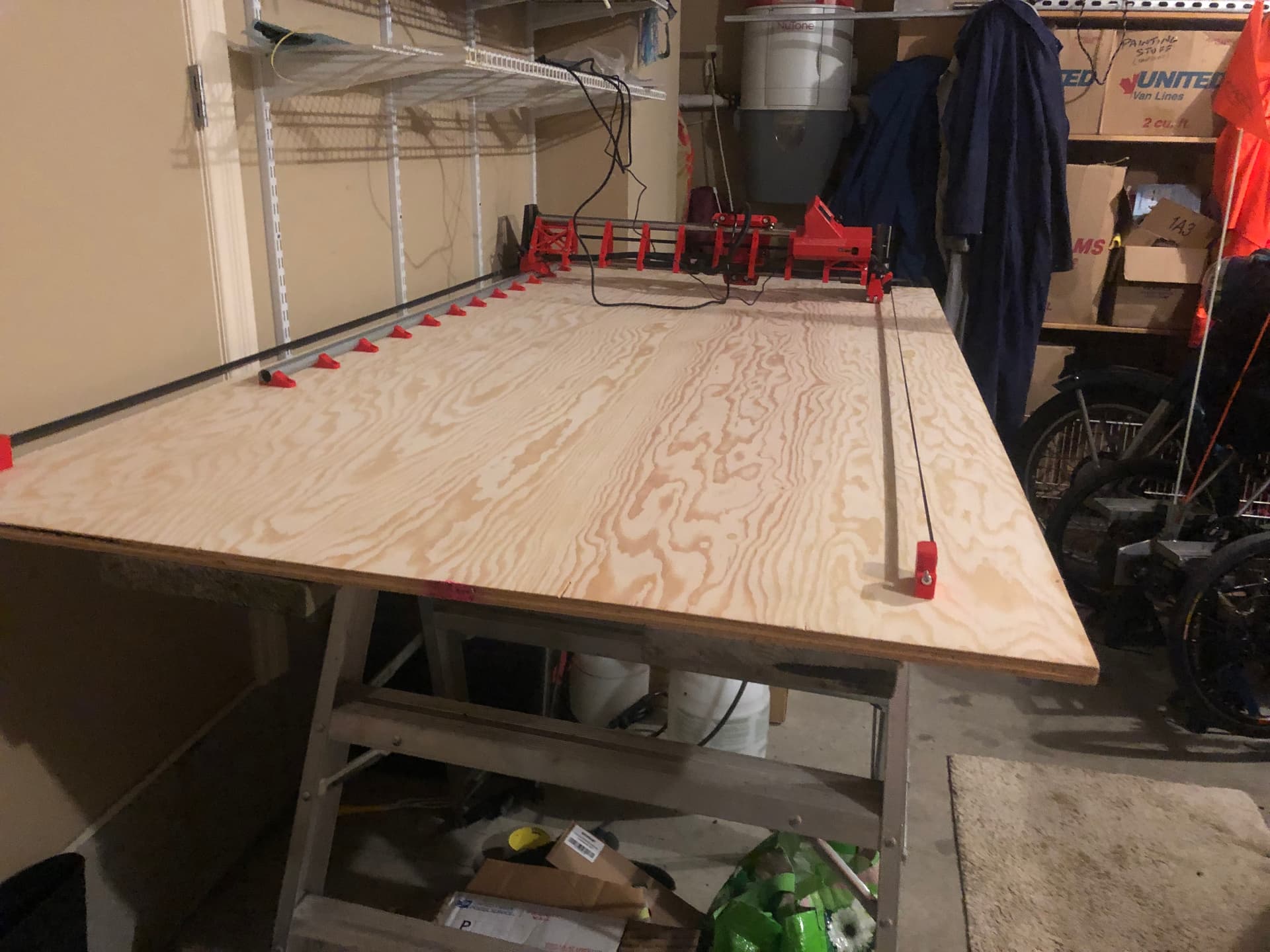
I managed to get to the lumber yard and pick up a couple of sheets of 3/4" ply (factory grade), and after tossing a lot of ideas for a table design around, I decided to scrap the idea of building a torsion table for now, at least until I get a few hours of cutting experience behind me.
For now I have set up a single sheet of plywood as a temporary work surface, which should allow me to cut out my aluminum struts for the short gantry, as well as aluminum XZ and YZ plates to replace the printed ones I’m using at the moment.
I’ll build a basic full size table over the next few weeks, but with holidays fast approaching, that may not end up happening until the new year.
3 Likes
Well I finally found enough time to get Little Red moving on the larger temporary surface (I can’t really call it a table at this point, just a sheet of plywood as noted above.
I did a quick check for square, and with X = 770 mm Y = 1400mm , the difference between the two diagonal measurements was +/- 1.5mm. Pretty darn close for a first attempt IMO!
Next up was the “crowning achievement”…

There is obviously a couple of low spots on the surface, and I just strapped the Sharpie to the tool holder, rather than using any fancy spring loaded pen holder, so I can’t really expect perfection. But it does prove that Little Red is fully capable of moving around as directed by a gcode file.
I also received an early Xmas present to myself in the mail. I bought a 1/8" Makita Collet and a whole bunch of various end mills from Sienci Labs. I was going to buy from the V1E store, but with international shipping and the usual costs and delays associated with that, it was faster and cheaper to get them from Sienci, who are conveniently located in Canada.
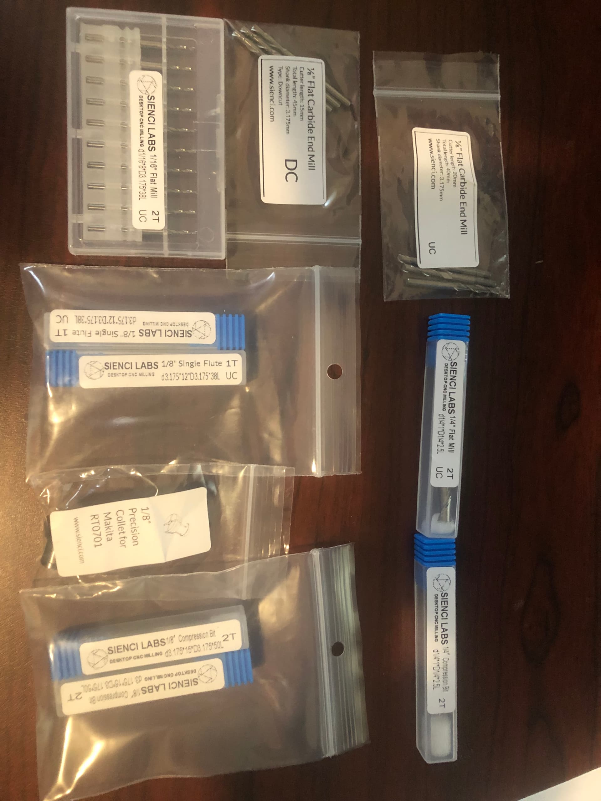
So I think that I’m almost ready to start cutting the aluminum struts for Little Red. I might try to shim up the plywood in a few places to get rid of some of the worst low spots first, and with Xmas madness just around the corner, it may be some time before I actually get cutting.
6 Likes
Congrats on the crown and progress!
1 Like
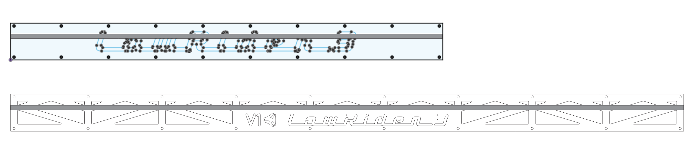
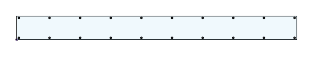
The learning continues. I’m making slow progress in tackling Fusion 360, and have accomplished the seemingly trivial but frustratingly complicated task of drawing out the struts for the Little Red build.
I made a mostly parametric blank plate at 942 mm x 80 mm. I’ll double up two of them on the bottom, and then use a single one as a base for the front and back of the gantry.
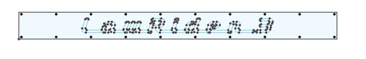
I added and resized the LR3 graphic that @DougJoseph created, which will fit on top of the blank on the front of the gantry.
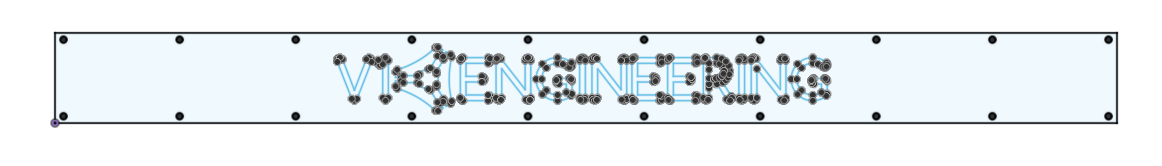
I also added and resized the V1E Logo, which will fit on top of the blank on the back of the gantry.
That seems like fairly good progress for this weekend. I’m going to get some test material (cardboard, foam, etc.) and do a test cut before trying the initial cut in aluminum.
Stay tuned…
3 Likes
For anyone who is not pretty experienced in Fusion, that which is seemingly trivial can be seriously non-trivial! Been there, done that, got the t-shirt, and washed it til it’s unreadable. LOL
3 Likes
It took me a couple months before I figured out how to use sketches to create bodies, so I feel your pain…
1 Like
Fortunately the several months that I spent trying to learn FreeCAD helped out a lot when trying to learn Fusion 360. A lot of the concepts are the same (or at least similar), but the workflow varies a bit (actually more than a bit).
2 Likes
Warning again: Don’t forget there is a belt that serves as a fancy strikethrough. Don’t ask me how I know. ![]()
2 Likes
Yeah, I thought about that, but I think it will look better in the larger size rather than trying to cram it under the belt. Maybe I’ll regret that decision once I see it built.
You can check how it looks with mine: Der Froschkönig - Lowrider 3 in Oldenburg, Germany - #73 by Tokoloshe
If I had known I would have made it smaller. ![]()
1 Like
Yes, I see what you mean. I wonder if there is a clear belt for sale anywhere? ![]()
1 Like