I think it’s “Lines” in Cura
2 Likes
Hadn’t thought of it like that. Makes sense. Similar to a fiberglass or CF part with alternating weave layers.
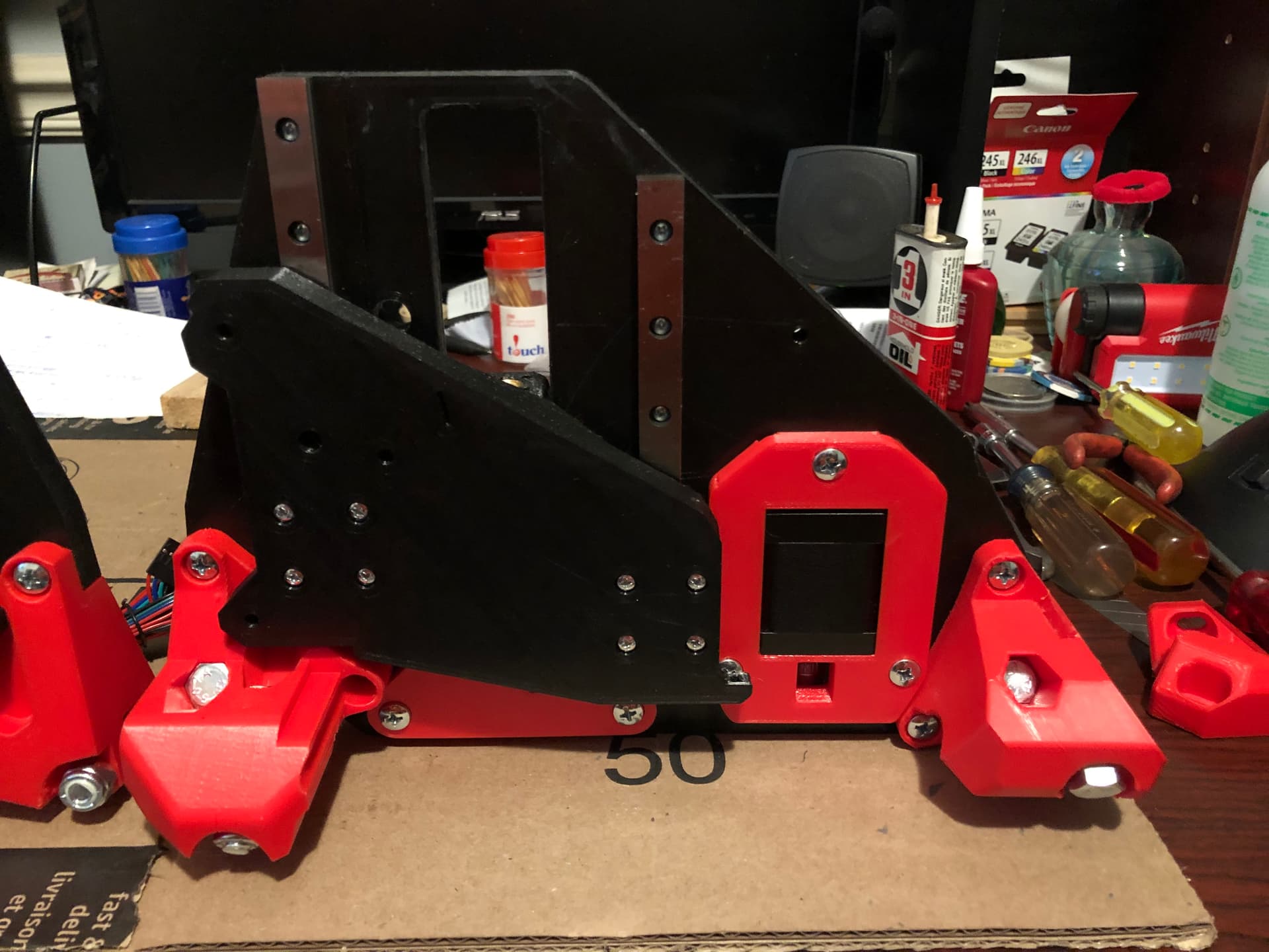
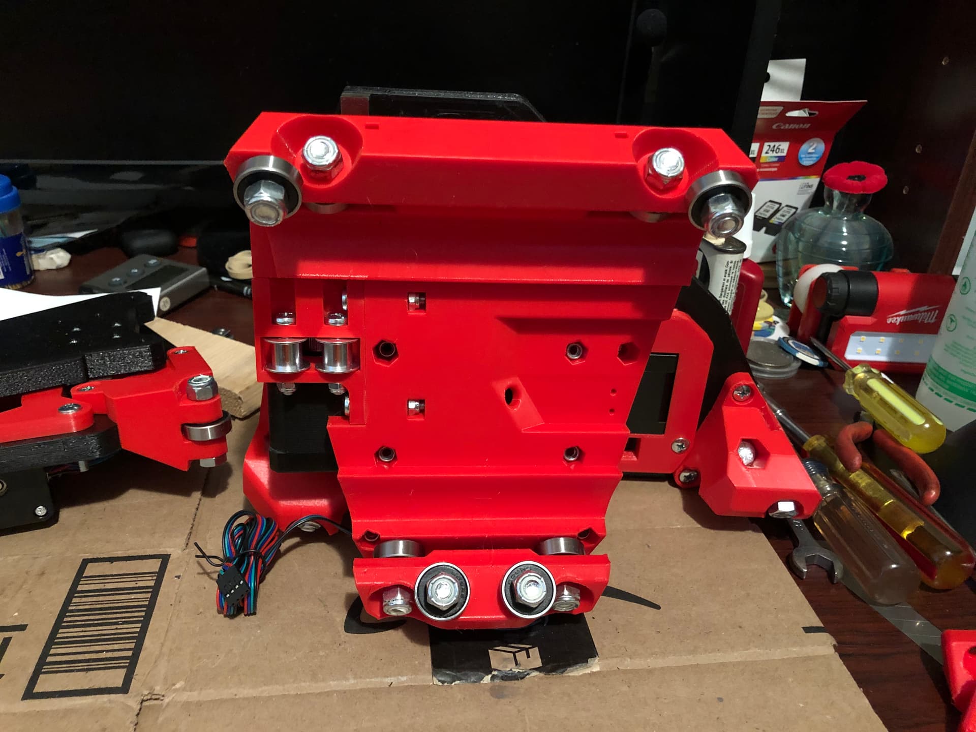
Modest progress - assembly has begun!!!
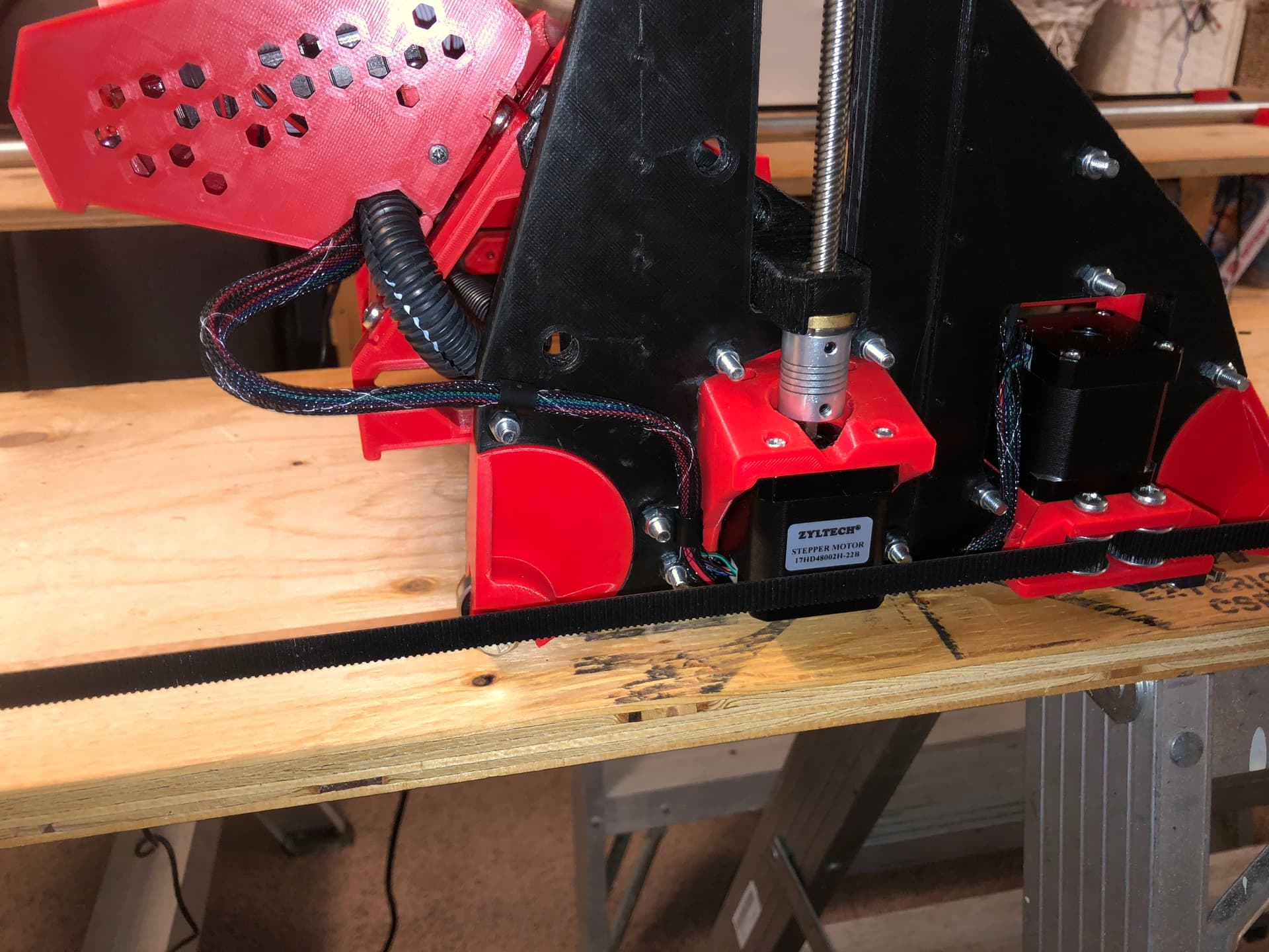
Printed the tool mounts, then installed all of the bearings, idlers, gears and stepper motors.
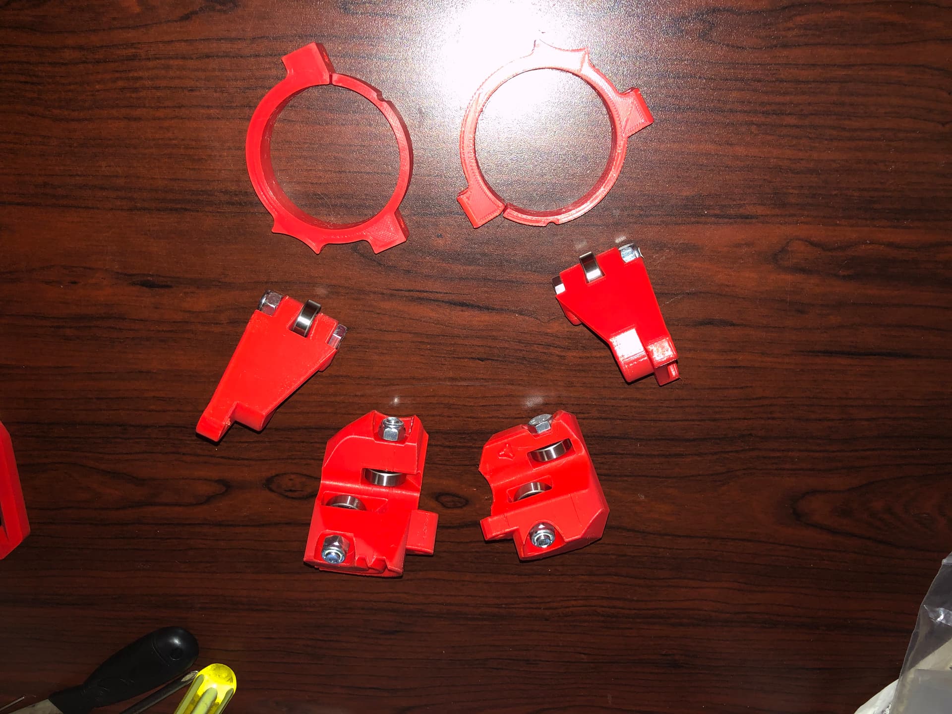
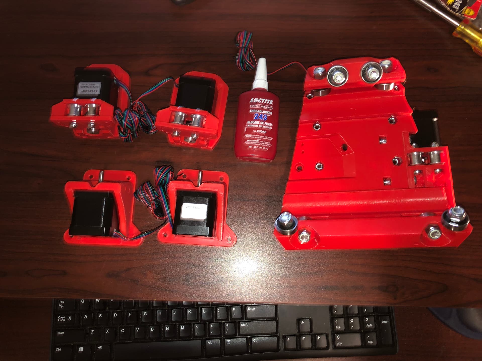
And yes, I firmly tightened the grub screws and used Loc-Tite.
I also assembled the gantry (using more braces than needed, but I have several extra in reserve for the next phase, which is a longer (wider) build)

Coming soon is the epoxying (is that a verb?) of the split YZ plates, then installing all of the bits and bobs that attach to that flat part. Stay tuned.
6 Likes
Watching the (24 hour) epoxy dry…
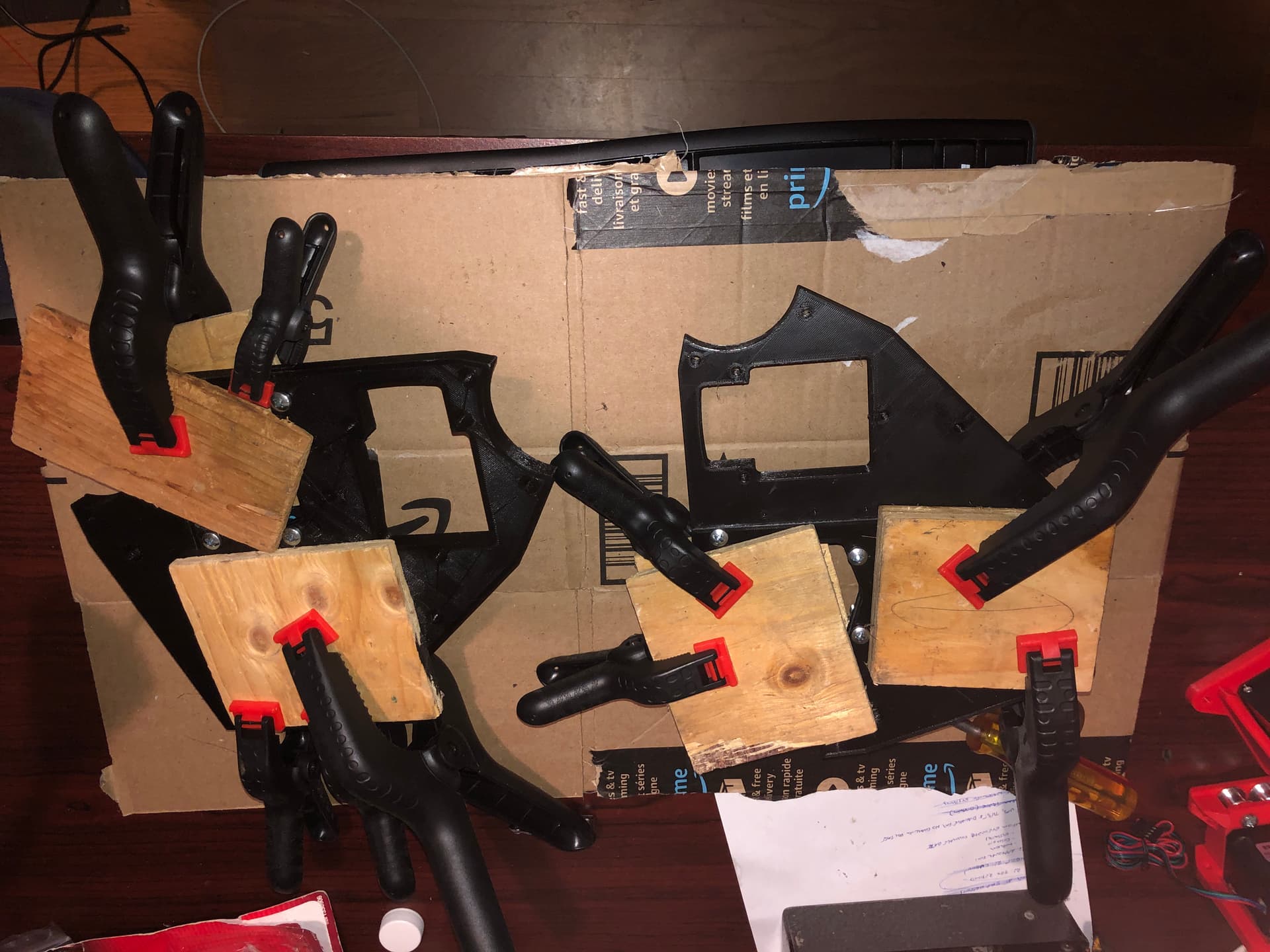
It’s like watching paint dry, except slower (and you can’t see the color change).
7 Likes
Epoxification?
3 Likes
Curating the cure…
You know its done in my house when the dog hair doesn’t stick
1 Like
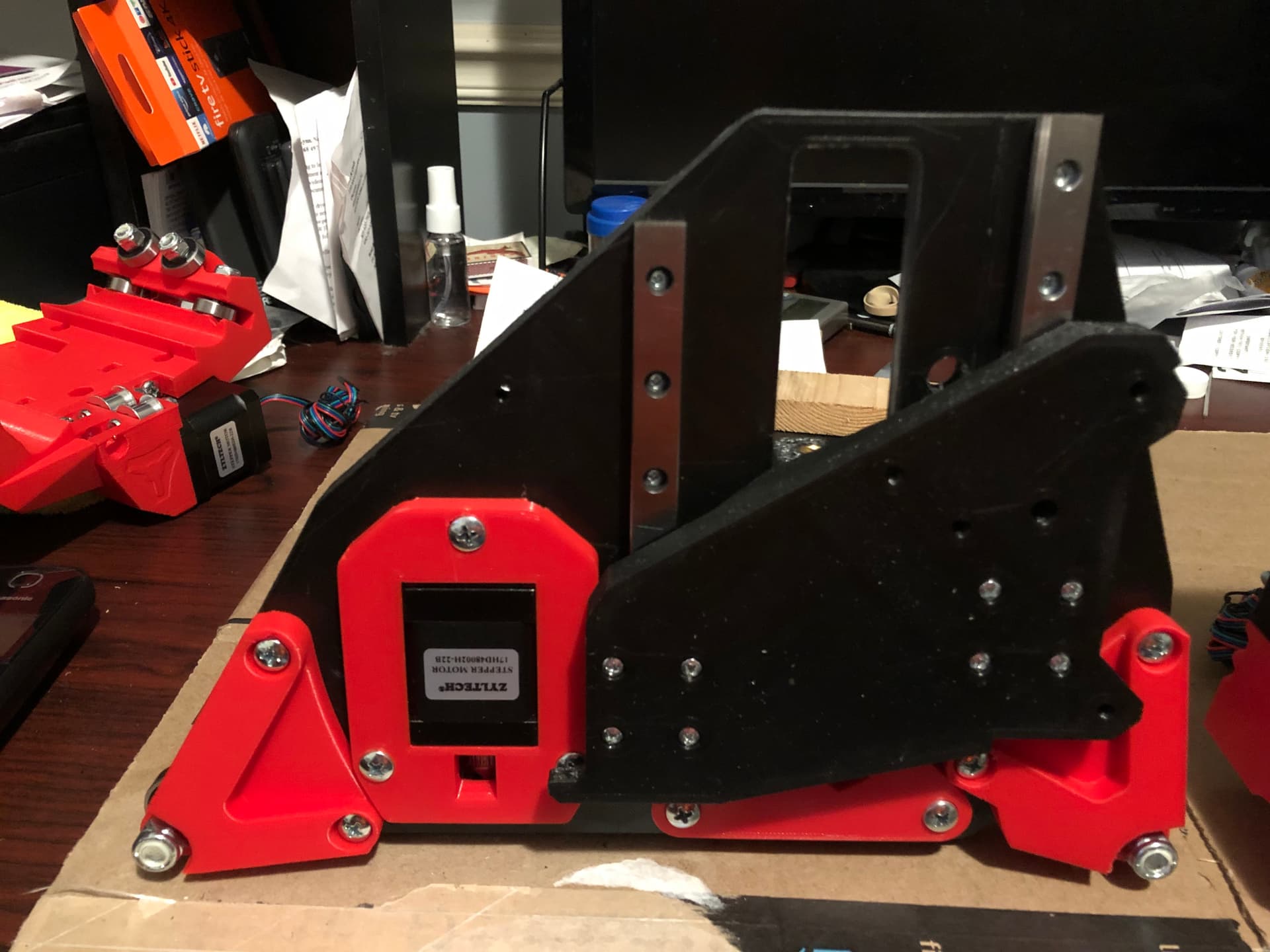
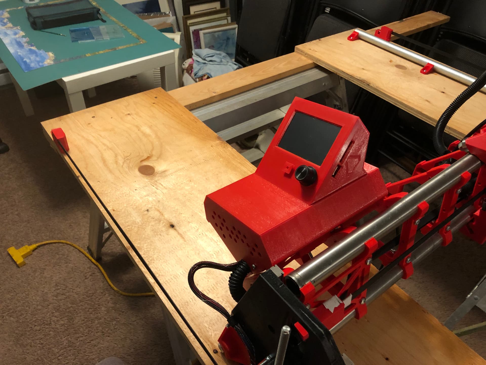
Introducing - “Little Red”!
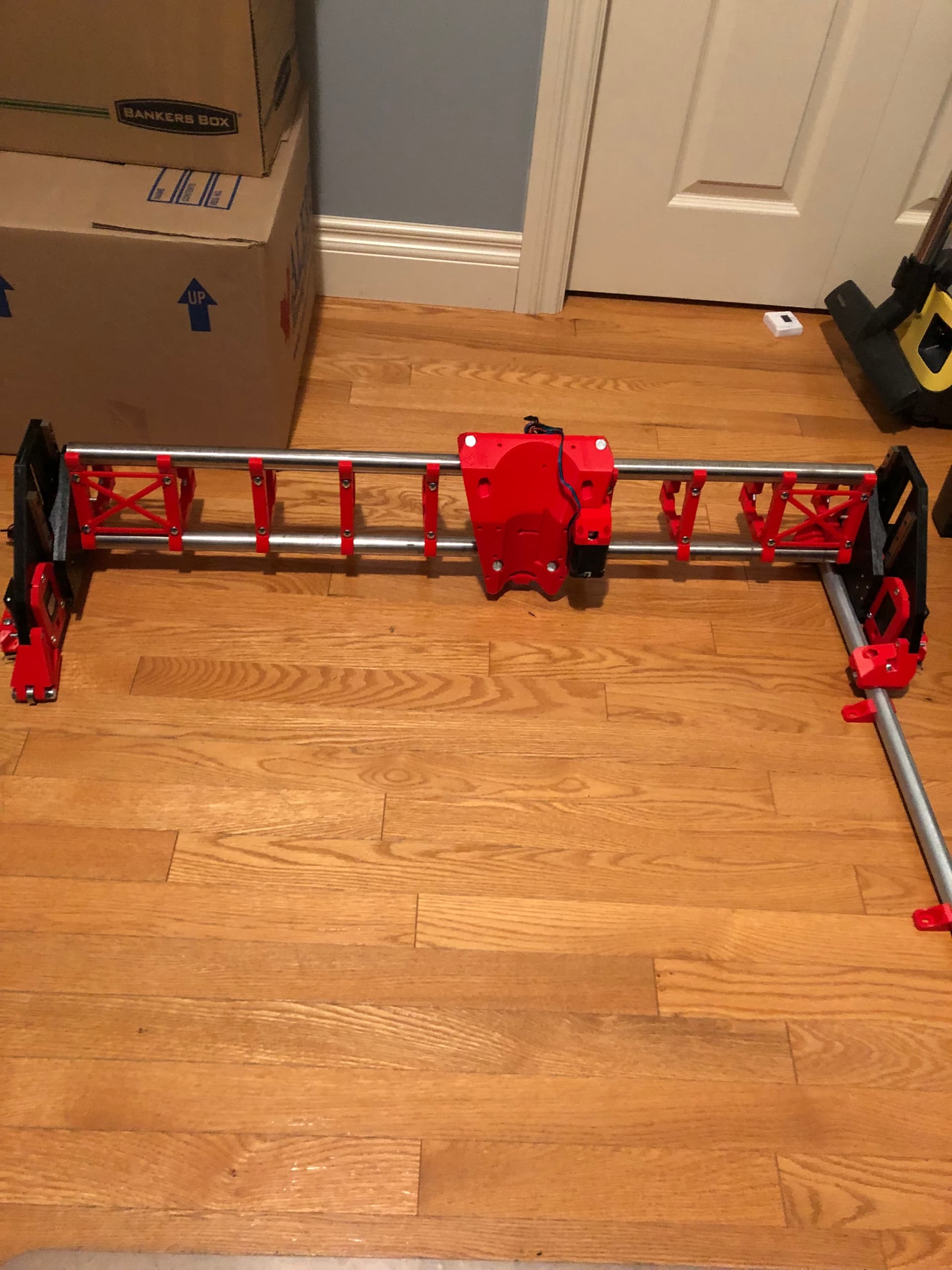
…or at least the bones of it.
This version is the interim build - 30" cutting width, and about 52" cutting length. I’ll be using it to cut permanent struts (2.5mm aluminum sign stock) for this version, and possibly for the larger “Big Red” version (or I might wait until I know the exact build size, which is still TBD, dependent on figuring out the side belt mount thing, aluminum thickness, etc.).
Once the smaller struts are installed, I’ll also use it to cut aluminum XZ and YZ plates (6mm or 9mm, not sure which yet) to replace the temporary printed ones…
It will be too small to cut the pieces for the table, unless I use my table saw to rip the plywood sheets into smaller sections first. I was hoping to avoid that and do the entire project using the LR3.
4 Likes
Wohoo, the third fairy tale CNC! ![]()
1 Like
Hadn’t thought of that angle,. Actually there wasn’t much thought at all. This is the small one, and there will be a big one, and they will both be red. So… Little Red and Big Red. (I tend to be literal ![]() )
)
4 Likes
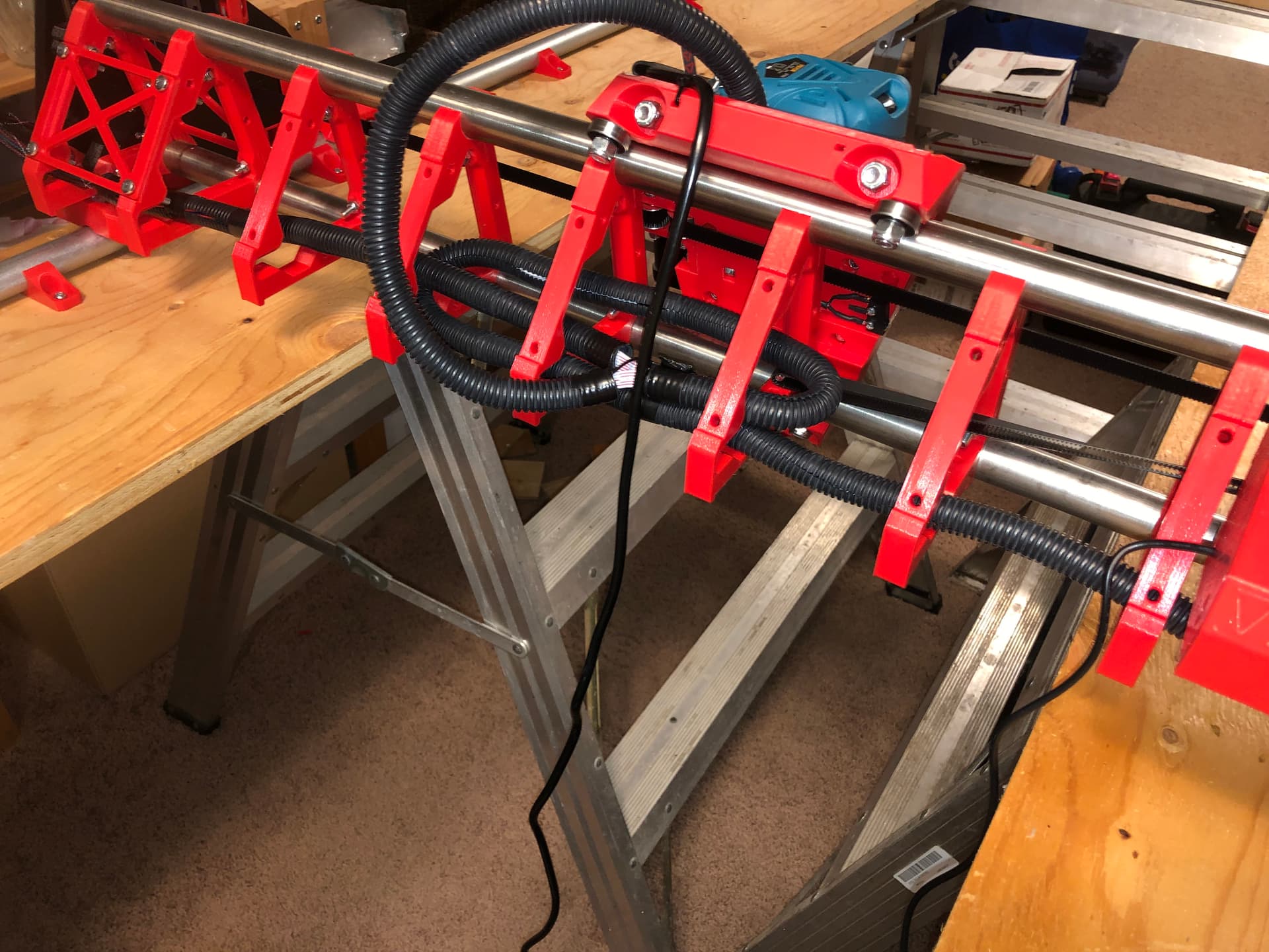
WOOHOO!!! It’s starting to look like a real LR3!!!

I don’t have an existing table for this, and I don’t have a full sheet of plywood or MDF to mount this to yet, but I did have a couple of leftover 8’ pieces of 3/4" exterior grade ply and a couple of pieces of 1x4 in the garage, so I cobbled together a temporary table that will suffice for me to do a few movement tests and to learn how to use the machine.
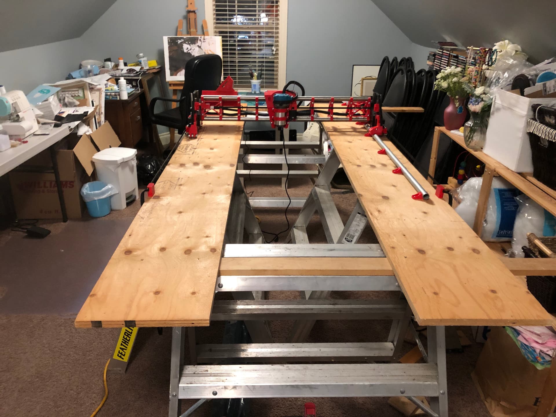
I used some 1/2" split loom for the wiring extensions in the gantry and controller box, and some small mesh loom (the stuff I bought from Ryan was a bit larger diameter, but I found some smaller stuff laying around) for the wiring on the outside of the YZ plates. I used 1/4" plastic “R Type” cable clips to attach the wires to the 5mm bolts on the outside of the plates. Looks not bad IMO, but once I build the final version, I’ll probably use heat shrink to encase the wires rather than the mesh loom…
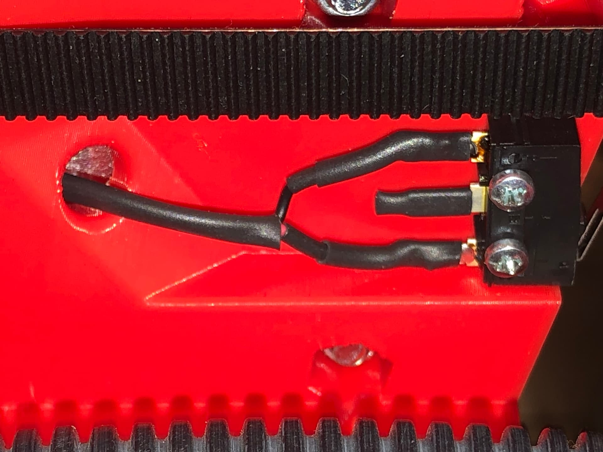
Speaking of heat shrink, I had a few challenges with the crimp terminals for the end switches, so I chose to use solder connections on all of the switches instead. I used heat shrink on all of the terminals, as well as the first several inches of the wires.
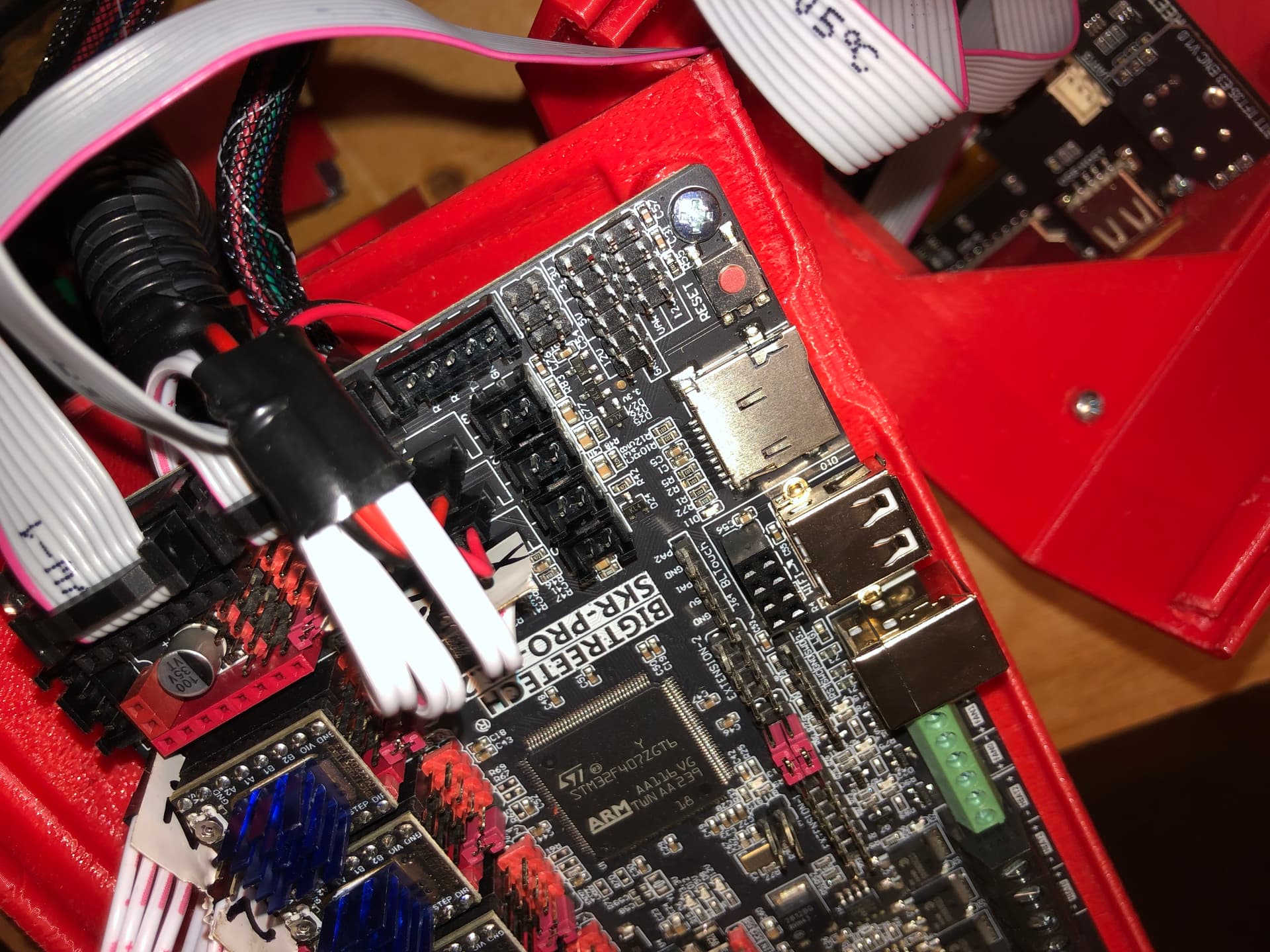
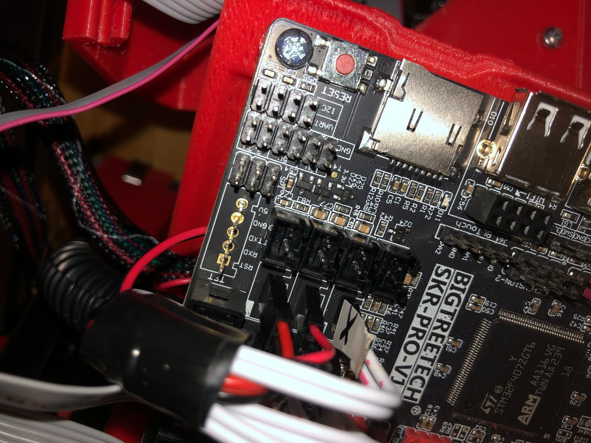
I used @DougJoseph’s remixed SKT/TFT case (low fat version). I didn’t have the DC power plug that it was designed to use, but instead I just tie-wrapped the power cable to the “sled hold down bracket”. Otherwise the whole thing worked very well, and I was pleased that it had ample room to fit all of the cables easily.
I was pleasantly surprised to find that all of the stepper motor connectors on the SKR board already had the JST connector clips removed. It made life much easier.

However the connector for the black wires from the display was still there, and I had a few nervous moments yanking on the connector with a pair of needle nose pliers trying to dislodge it. I had to apply so much force, I was seriously concerned that I would break the board, but eventually managed to get it off without too much drama.
I do have a couple of questions:
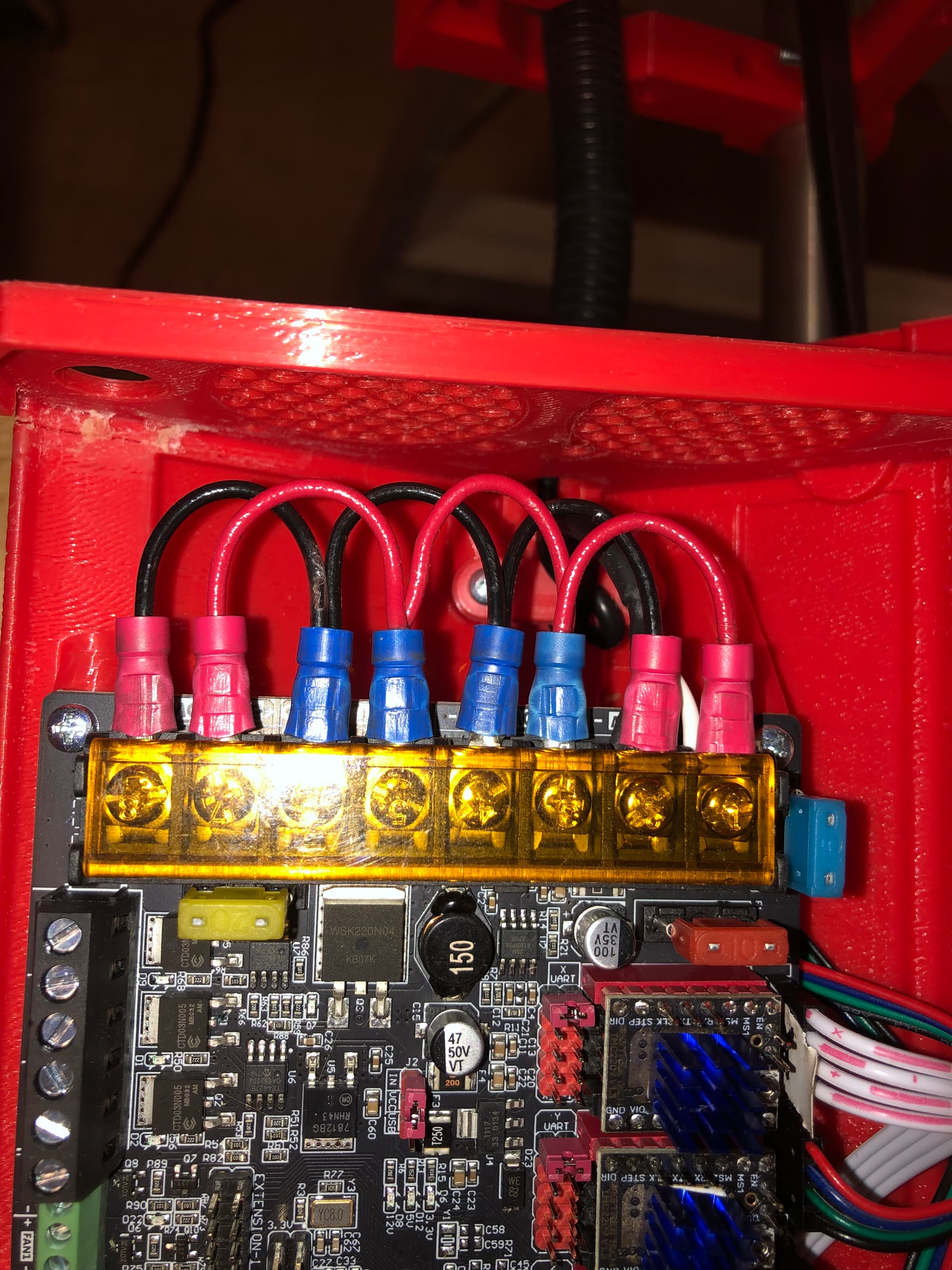
I wired up all 4 sets of DC power connectors, whereas the instructions only mention wiring up the first two. Will this be a problem?
Second question - I noticed a small hole in the front belt holders. What are these for? I thought maybe for adjustment screws for the endstop switches, but there are no nut holders, so presumably the screws just thread into the holes???

Anyways, I am pretty much at the point where I can plug it into the wall outlet and start having it move under its own power. Many thanks to all for the encouragement and guidance to get me this far.
Stay tuned for future progress reports…
2 Likes
Looking awesome!
I don’t know for sure on this. Need to defer to someone else.
Ryan (@vicious1) has a good habit of remembering to design a screw hole on each end stop for the added option of correcting a lack of homing and/or lack of square, by inserting a screw that the end stop switch would touch early, instead of the main end stop later! I suspect that is what this hole is for.
2 Likes
Hopefully not, but the second 2 are for a 3D printer’s heated bed. When that gets turned on, the input gets connected to the output. For safety and “less to go wrong” I would disconnect those. Do leave the other two, they are needed.
As to a problem… look closely at the polarity labels. They are not + - + - + - but + - + - - + + - the “Hot Bed” output is reverse polarity, so this will result in a short circuit to your power supply. Bad news!
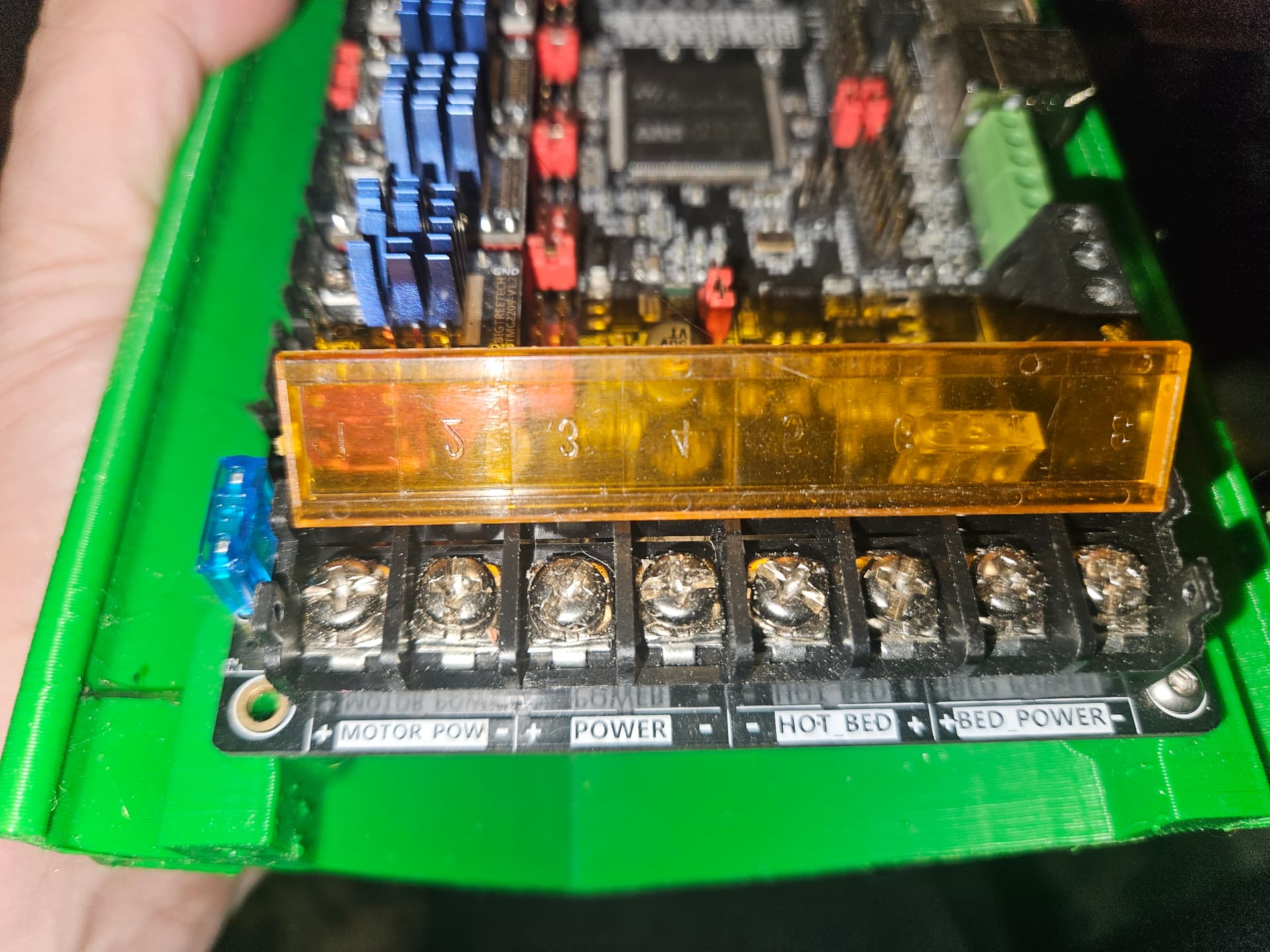
… you will want to disconnect the “Hot Bed” and “Bed Power” wires…
2 Likes
Holy Crap! Thanks for pointing that out, I completely missed it. I glanced at the first two and the last one, and missed that the third was reversed.
I was thinking initially to wire the bed outlets up to possibly use for other outputs in the future, but your “less to go wrong” point rings true (especially after seeing the reversed polarity). Wire snips and screwdriver, here I come.
1 Like
You can leave the “Bed Power” connected. The “Hot Bed” is the output to the heated build platform, or “Heater 0” for Marlin. You can use that for a relay control.
2 Likes
Looking great! Have it make its own robot noises!
Soldering seems like the best plan. I think several other people (myself included) have done this.
2 Likes
yes, but really not needed or used.
2 Likes