At the risk of linking to someone else’s store…

(edit - linked to wrong topic - sorry!)
I can certainly do that! I have it all disconnected (making a little “case” for the tiny board) let me hook it all back up and test and I will upload a picture.
@thedevilsjester, YOU ARE THE MAN!! I’ve been hesitant to try this myself just yet as I’ve still got a couple of points I’m unsure of. While you’re at it, and just to plant the seed for future ideas/information, I’m hoping I can find a second pin to get an on/off signal from to control a relay that I’d like to use in order to control the shop vac that’s connected to my vacuum table. In the perfect world, I could use the consol within cncjs or octoprint to turn on the vacuum by sending a command (which could easily be made into a macro I’d imagine) home all the axis and then kick off the needle cut which would then send the desired PWM signal to my ESC for the brushless motor attached to the needle. Once all is done it would turn off the needle, return to x,y home, and then kill the vacuum.
Ultimately what I’m most curious about is where you are pulling the 12v and 5v from to set the high and low values for the conversion board. @jeffeb3’s post explaining where the pads would be connected mostly makes sense to me but I’ve yet to verify how I would connect the LV1: Laser(-) and LV2: Laser(+) to the 3 pin connection on the ESC since that is: ground, power, and signal.
While proofreading my message I recall a subsequent message from @jeffeb3 where he says
So does that mean the above mentions “signal” wire on the ESC would be the corresponding fan (-) wire?
Yesterday was a good day!  I was able to use pin 53 to trigger a relay board in order to turn the shop vac off and on again. I did have to wire in a 5v buck converter to get power to the relay board. Ultimately I took a single gang outlet box and wired the black wire of an old power cord to the relay and then to the outlet so whatever I plug into the outlet will be triggered off and on by the board. Added
M400 ; Wait for moves to finish before continuing
M42 P53 S255 ; Set Pin State
to the end of my script and it now shuts the shop vac off when the job is all done. I’ve been using CNCJS to control the CNC so I just added a macro to turn the shop vac off or on so I can start it to suction my foam board to the table before running a job.
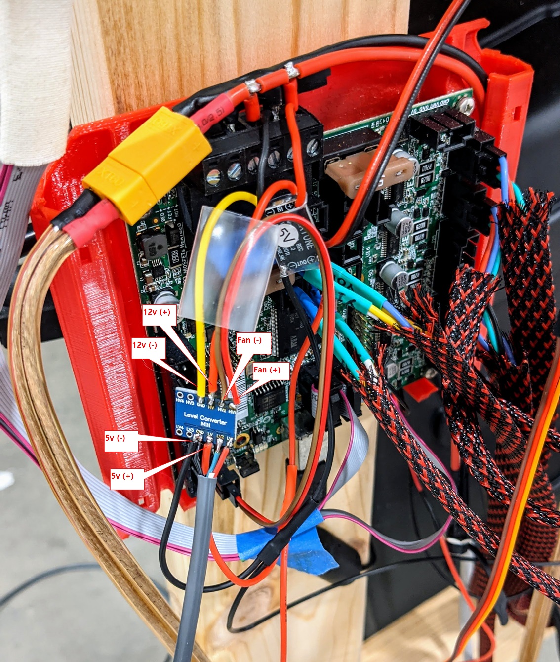
Hey @thedevilsjester and @jeffeb3 I know you are both probably super busy but you seem to both have a better understanding of how the PWM signal work on the Achim board than I do. I went ahead and tried to connect the fan to hv1 and hv2 pads of the fan (+) and fan (-) I then connected the 5v to the LV and ground, From what I understood of the previous comments the fan (-) is the one that pulses so I considered that the signal wire and then pulled 5v and ground from the 5v buck converter I’m using. In order to test I hooked it up to a standard RC servo but it’s not controlling the servo at all. Could you tell me what I’m doing wrong?
The negative terminal (that the fan connects to) oscillates between ground and open. I think it may also be tied through a resistor and LED to 12V, so it should go basically to 12V when the pin is floating.
I’m not sure what it’s like on the signal side of the mosfet. But I’m pretty sure you will need to tie the grounds together, or the buck converter can just be floating away, completely separate from the ground on the archim.
Are the two sides of the ground on the level converter tied together? Is there a voltage between them?
so you’re saying I should tie the 5v ground and the 12v ground together?
edit: well I checked between the yellow wire (12v gnd) and the brown wire (Fan (-) and it the multimeter read 12v. So I’m definitely not understanding something around the term “floating” that you’ve used numerous times
I’m not sure. I would like to know the difference in voltage between the 12V(-) and the 5V(-).
If the fan is off, the fan(-) should be 12V higher than 12V(-). That’s because the fan (-) should be floating, and there is an LED pulling it up to 12V when it is off. When it is on, it will go to ground, and that will turn on the fan.
well I checked the ground on the converter and it had continuity. Would it matter if I’m using Fan 0 or Fan 1? I currently have it hooked up to fan 1 according the the diagram on the v1 site.
Shouldn’t matter.
An RC servo shouldn’t respond to PWM. It is based on pulse width, between 1ms and 2ms. Can you check between the pin across from fan (-) and ground and see if that changes when you send different M106 commands?
The pin across from fan (-) on the 5v side of the converter is the green wire. (just stating to ensure I’m checking what you are referring to) When I send: M106 P1 S256 to the green and gnd have a 1.5 mv reading so basically nothing. After M106 P1 S5 those same wires have a reading of 4.51v. I guess I mistakenly assumed that a servo reads the same as an rc electronic speed control. I could just hook up my motor and see what happens lol I’m just really hesitant to test that way lol
The esc is also a PPM signal. The fan is PWM. Can you instead use M42 and a servo output?
I thought we were trying to control a 5V laser.
yeah, that is totally my fault… I wrongly assumed that the ESC used the same PWM signal for control as the laser would use. I’ve seen mention of servo pins before but only on the Rambo board, I couldn’t find any servo pins on the Archim board. Are you aware of a PPM pin somewhere on the Archim board that I could use?
Servo pin 0 is set to pin 20.
That sounds familiar though, like it was not pwm enabled, further up in this thread?
You could swap the pins for fan1 and servo 0 and then try the wires you have with M42.
so when you say swap pins do you mean change the values in that .h file or remove the ‘#’ from line 60 and physically move the signal wire to pin 20 on the control board?
I mean swap the numbers in that file.
I got it confused. It was M280 to set the servo:
ahh yeah that explains the error I got on that line when I tried to compile the sketch
edit: I’m not sure if that includes the “20 // D20 PBV12 (Header J20 20)” or just the number 20?
The // and anything after it is a comment and it will be ignored.