ok I just swapped the “20” with the “4” but left the servo line with the “#” in front of it. I’m not sure if that mean I can now send the M280 P0 S256. the consol says that is is an Unknown command
edit: did some more testing and sending: M106 P0 S256 sets the voltage on pin 20 to 3.25v but it stays there till I get down below S127 when it drops to almost nothing. I think that is why @thedevilsjester ended up using the fan pins
ok I probably know enough to be dangerous so I want to check if this is ok to do. I was looking through the advanced config.h file and saw there was some laser_feature settings that were not enabled I’m wondering if I can just enable the laser feature setting and then add a line to the pins.h file for the laser pwm pin (say 20) and then flash that to the cnc, I could then us the M3 and my current voltage converter to step the signal up to 5v if needed. I hopefully this would work but hesitant because it just seems too easy. why wouldn’t it be enabled from the beginning if it was that easy.
yeah, that was my thoughts too! I tried to do some research online and I saw it mentioned the servos run off PWM but if I search ppm it mentions it is used for ESC’s too. That’s why I was testing with a servo since I assumed they required the same signal. I’ll try changing servo 1 to 20 instead and give that a try.
There are some PWMs that will look like a PPM signal. The width of the pulse should be something like between 1ms and 2ms. The 2ms width is full on. But that still is about a 60% duty cycle.
Maybe an analog servo would work on PWM, but not all of them would.
I’ll try swapping to Servo1 and see if that works. From the browsing I’ve done on the site, it looks like you’re pretty familiar with the marlin firmware. Would it be possible to configure a pin to send the PWM or ppm signal that’s needed to control the ESC? With all the trouble I’m having trying to get a signal for the ESC would I also have an issue getting the necessary signal to control a spindle later on as well?
I tried to increase the number of servos to 2 since that’s what is listed in the pin_.h file but the sketch didn’t build. it was complaining about the delay not having a long in it. I might look at what is used for the Rambo 1.4 and maybe that will tell me what I’m doing wrong.
Is there any chance you’d be able to bump Ultamachine on this one again? I’m sure there is no shortage of work on their end but if you’d be able to get them aware someone is still interested in this it would be really awesome.
I have three outstanding emails with Ultimachine tech, that is the oldest one. Not sure what I can do at this point, or what their direction is with the archim’s. My order is later than expected as well so my best guess is Covid related staffing issues.
I can take a look and see if it is something I can figure out and submit a PR to them, I could then press that to get merged with them. I am going to try and submit another archim related Marlin PR right now. I will try and take a look at this issue if it doesn’t take too long. This is far from my field of expertise so don’t get you hopes up too much of me figuring out his higher level stuff.
absolutely no pressure I’m still learning a lot as I go. I appreciate you taking another look at this though I can’t image I’m the only person who would benefit from this feature.
I really think it should work to set the servo 1 pin to the fan pin, then set the number of servos to 1 and then use your voltage converter to take the 12V to 5V.
So I did that, I set the servo 1 pin to 4 and uncommented the number of servos and set that to 2 but the sketch didn’t compile. It was complaining about the servo delay not having a valid argument so I just dropped it assuming there was a lot more to it than I could see or easily understand
So I was looking back through it and realized that in order to get past the error I was seeing I need to add additional values to the “SERVO_DELAY” definition equivalent to the number of servos stated. I fixed my mistake and the code loaded fine. I tried playing around with the existing fan pins with no luck but just for fun before I reflash again I tried using the servo pin 0 and another conversion board that adjusts the voltage up to 5v and it works with the servo!
So here are the steps to get this to work with minimal changes. (it would still be nice if we could get the stock firmware updated so people don’t have to manually do this)
uncomment line 2407 and change the number to 2 since there are only 2 servo pins listed in the Archim_pins file
change line 2412 to the following (since you have 2 servos you need two values in the array) #define SERVO_DELAY { 300, 300 }
I thought a voltage converter was needed but I tested controlling the servo without the voltage board and it worked as well so this ended up being so much simpler than I was expecting!
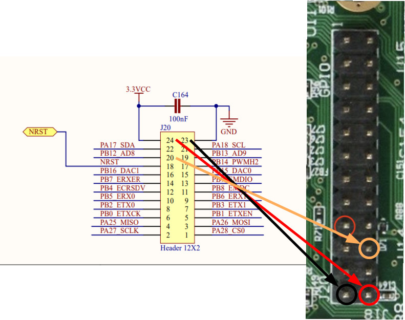
In summary, make the two modifications to the one config file and you can control a servo on pin 20 or 21 using M280 P0 or M280 P1. I’m pulling the power from pin 23 and 24 which are the bottom two pins of the board
Interesting. Pins 20 and 21 weren’t looking right for PWM, which is what that archim issue I pointed out was about. But servi code must be doing bit banging insteadof relying on the pwm timers. Nice.
yeah, I didn’t dig that far into it since I’m new to the firmware but I’m just glad it works For my motor/ESC I just send the M280 P0 S70 and that starts my needle cutter at 9400RPM every time it’s working perfectly now!! so very grateful you guys were willing to work through this with me
edit: I should mention that for my ESC I’m only using the single wire going back the ESC. The ESC is powered by the 12v comings from my power supply that powers the motor. I only highlighted the positive and negative above since they were used to control the servo.
Did they ever get back to you about this? I’m in a similar position I have my laser working using the logic lever converter but when I do pictures it seems like it can not change power levels fast enough. any help would be great. if I need to I can start a new topic.

 I’m still learning a lot as I go. I appreciate you taking another look at this though I can’t image I’m the only person who would benefit from this feature.