A day or two, but everyone is slammed. My orders just got bumped a little longer. No tech support reply yet. Usually when he does it is with a fix so hopefully he is testing it out.
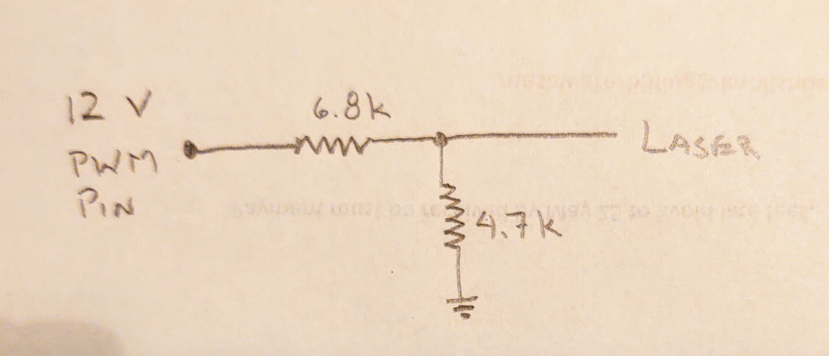
I think we could probably work out a circuit to use the 12V fan output. I would have to look at the schematic and see how it is gated, but if you have a variety of resistors, we could make something that would be close.
Or, you could just keep using pin53 and only have 100% or 0% power.
I am not comfortable enough with my electrical engineering skills to attempt such a task, though if it turns out that this board doesn’t have a pin that could be used for this, I would be interested to know if there was a good premade 12v to 5v step down that worked with PWM. I found dozens listed on various import sites, but I am not knowledgable enough to know what I actually need.
Unless my math is wrong, this should drop the 0-12V PWM output to 0-4.9V.
470 Ohms and 680 Ohms would do the same, but draw more current on the Archim pin, like wise 47k and 68k would produce the same voltage output, but draw less.
But the 12V is from the power supply, and it is switched on the low side. But the low side also drives an led. I don’t think the led would matter, but I remember having trouble with it when I tried something similar before.
This is an off the shelf part that can convert 12V PWM to 5V PWM:
That part looks like it converts between 3.3v and 5v (which would be handy if the laser didn’t recognize 3.3 as “on”). I am sure a similar one exists for 12v to 5v, I just don’t want to end up buying and hooking up the wrong thing (again, this is assuming that the Archim board isn’t capable of this by itself)
That part works for 12V. It is just the examples that are 3.3V and 5V. The datasheet for the mosfet has a max of 50V and you’ll really only be using the diode to bridge the mosfet anyway (it is bidirectional, but you’ll only use one direction). There is a review using 12V with 3.3V.
When the fan output turns “on”, it will pull the HV1 to ground, which will pull LV1 to ground, which will make the difference between laser (+), (-) 5V.
When the fan output turns “off”, HV1 will be pulled up to 12V, LV1 will be pulled to 5V (through a 10kOhm), which will make the difference between laser (+), (-) 0V.
Let me see if I understand this. I hook up any 12v to HV and any 5v to LV so that it knows what my high and low should be and then I can hook up 12v (input) to any HV# and get a 5v (output) from the corresponding LV# ?
I bought that little converter, and it works great. Thank you for the help with that.
The only issue I am having right now, is that I want to use FAN1(not FAN0), however it appears that FAN1 is always on. Any idea why that might be? A cursory glance at the firmware does highlight a few macros that treat FAN1 differently than FAN0; but I am not familiar enough with the firmware to know why.
@vicious1 No answer back from Ultimachine yet? While I don’t strictly need it anymore with the converter, it would be simpler (and helpful to others).
The second fan (fan1) often has a separate function. Something like being on whenever the motors are engaged, or if it is a heater block cooler, it will be on whenever the temp goes about 50C on the hotend. You can easily swap fan 0 and fan 1 pins in the pins file.
I must be missing something. Switching the pins in the header file simply determines which fan is associated with the (original) FAN0 pins. The (original) FAN1 pins are still always on regardless of which fan is set to control it. My guess is that there are certain behavioral attributes hardcoded to that pin, like the array in the file you linked earlier: ArchimAddons/variants/archim/variant.cpp at master · ultimachine/ArchimAddons · GitHub
@thedevilsjester I was wondering if you might have some pictures of how you got the laser all hooked up? I think I’m following @jeffeb3’s explanation on what goes to what on the little board but seeing how you were able to solve the problem would take any guess work out of it for someone less experienced in this.