Just in case. I have made a new release today, I have included all BTT touch screens in this one. Just unzip like always, dump all the files on your SD card and reboot, up to date as of today. Release 3/9/23 Roll up · V1EngineeringInc/BIGTREETECH-TouchScreenFirmware · GitHub
1 Like
OK,
I just loaded that firmware and seems to work.
I am going to open a new thread about modding the firmware, mainly the way the screen is presented than the actual workings of it.
1 Like
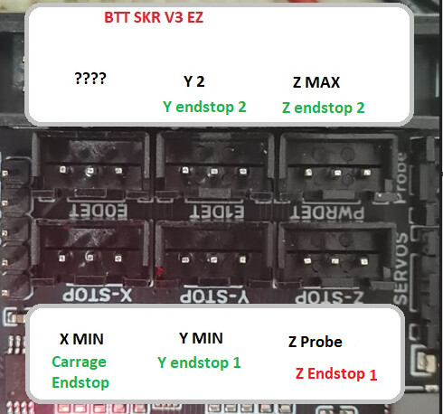
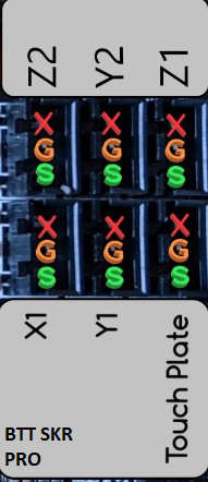
So i have mounted all the end stops and i am now checking what the board thinks is tripped
So i am doing a dual end stop LR as i plan on taking the unit off the table between uses, so resquaring the unit will have to be done every time, just to check.
so in my case i have put the control box on the rail side as that is i think how i am going to work with this .
Y Stop (one next to the control box and rail)
Y Stop2 (free side)
Z Stop ( Control box side)
z Stop 2 (free side)
PROBE
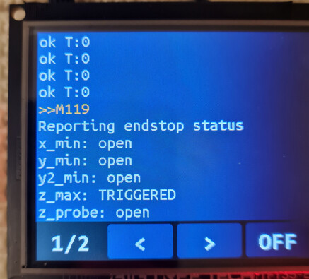
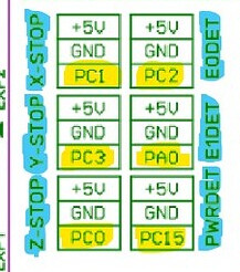
below is what the board thinks is triggered in each spot
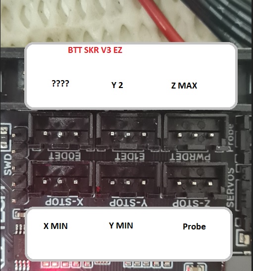
So as you can see the board thinks the PROBE is in ZSTOP and E0DET is not responding
I think that PROBE needs to be in E0DET and Z2 needs to be in Zstop
Jobs:
find out why the board thinks Zstop is the PROBE
Find out why E0DET is not responding
So,
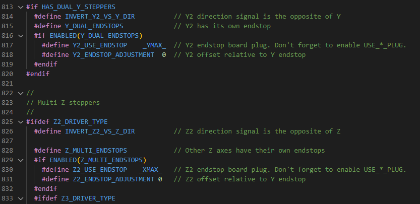
opening VSCODE I have all the ENDSTOPS inverted so they say open when open and triggered when closed.
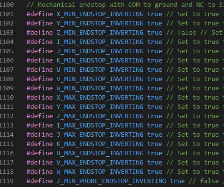
I have not touched anything else, here is where the endstops are defined.
But oddly they are not using those as the names it comes up with when you type M119
it uses Y2, ZMAX, PROBE, YMIN, XMIN
Can someone point me at the location for these or tell me why they seem to be different using the m119 command?
-=-=-=-=-
Edit with sorta answer.
so the M119 uses the “Names” of the axis listed here
Not sure how i got the other names, i think i was referencing the names on the board of the SKR Pro.
Its Friday…my brian must be broken, sorry
IT MOVES!
(no more robot noises, it makes it own!)
The X stepper is moving the carriage i am fairly sure teh right way…
Looks like the dual Y are working the right as well.
But only one of the Z motors is working.
In config adv, the dual Z section it there is a pin define there if I remember right. it might be for the Z2 endstop pin. If that board is not defined well that could be a bad define.
yep found it.
and it looks good
Hmmm let me switch motor wires and make sure the other z motor is actuall working…
-=-=-=-=-
EDIT
yep bad wiring or bad motor of the z motor. ok test the wiring and motor
We had to go through a bunch of hoops to make it work in DualLR.
Those should all be set for you though.
The endstop locations for dual lr pn an slr pro should be right here:
https://docs.v1e.com/electronics/dual-lr/#wiring
Zmax and Xmax should be used for Z.
Zmin should be the probe.
1 Like
Thanks jeff.
One of the z wire is faulty, but work got busy so i could not keep everything straight in my head, which you could see with the random posts.
I read those now and say “what the hell was i saying” lol, well you get that.
Anyways work got busy and i could not get back to it, so I will test all the end stop and motor wires onntuesday or wednesday.
2 Likes
I had similar (I think) trouble working out the endstops for mine.
For memory, since I changed around which plug was being used, I ended up having to change the homing direction.
Not sure if its any help to you though:
Edit: actually I think my trouble may have started from defining my own firmware from scratch (using the V1 firmware as an example to help me along)
We might be banging our heads on the wall because it looks like marlin has been making all sorts of changes to try and get this board to work right. BTT Octopus Max EZ 1.0, SKR 3.0 / 3.0 EZ Followup by thisiskeithb · Pull Request #25495 · MarlinFirmware/Marlin · GitHub
There have been several skr v3 PR’s lately.
1 Like
Thanks for that info Ryan,
ok, well it is interesting that there has been a bit of work on the board. I wonder around what, the “EZ DRIVERS” or other stuff.
I am burning the candle at four different ends, the girlfriend, the sailboat work, the table for the LR3 and the LR3 its self. Throw in a 9-5 job and I i really need to get this LR3 off my plate, lol.
So I have taken the weekend off (mostly) and come back with a bit clearer head, hopefully.
I found a few wiring mistakes, and now all the motors are turning in the right direction i think.
either way not a big deal if they are not.
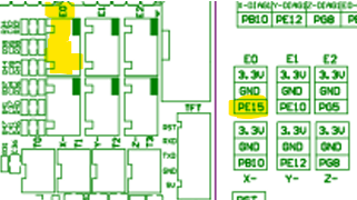
the biggest issue i have now is that the end stops are SORTA wrong. I updated my diagram to show what is connected where.
and now the actual end stops shown by the m119 command (ignore the second page its just the m105 report, these are the only end stops listed.)
Now, I have only got the 5 homing end stops connected and not the probe just yet.
2 x Y carriage end stops are working
1 x X carriage End stop is working AND HOMES CORRECTLY (small victory!!)
2 x Z end stops
BUT
Z is were i am having my issues.
One of the Z end stops is ok, as it is using “z_max”
but the other is using “Z_Probe”
Ok, Questions.
Can someone please do a M119 and confirm what they are seeing for the entries listed.
Is one of the “Z End stops” set as Z_Probe?
If you have TOOL HEIGHT setting thing, be it the V1 eng on or another one, does that show under the M119 command?.
And where does that Z HEIGHT probe get connected on the board? As my board has a “PROBE” space and you can fit a BLTOUCH to that or does it get connected to the 6th end stop E0DET
you are missing Z2 max.
Yes
The Z probe is usually the Z min port…your board could be different but should not.
You can easily test this but checking each port with a probe or switch, one at a time. Trigger it run M119 and see which changes. Look at the skr pro instruction in the docs and you will see some pictures of how we plug them in and how yours should be functioning.
Thanks @vicious1,
It confirms that the board is almost there.
(from here on i am a bit lost and i am trying to work through the different files and how they interact. It get a little confusing as i am comparing the SKR PRO that we know works to the SKR V3 EZ and see if i can see what is wrong. I found it, but its a bit of a ride in my strange brain, soz.)
@jeffeb3 or Ryan,
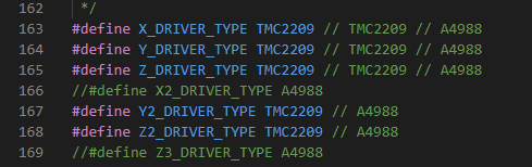
So it seems i am missing Z2 MAX as Ryan pointed out.
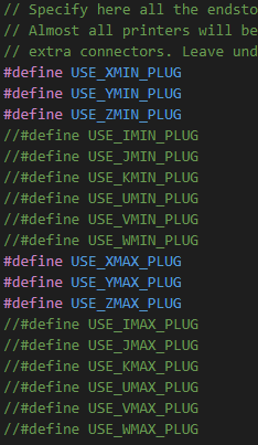
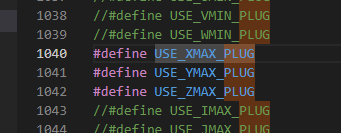
I have checked what little I know and was able to figure out, Z2 is enabled and is using the _XMAX PLUG
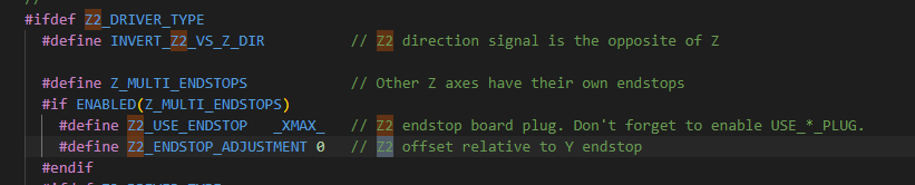
I made sure that the _XMAX_PLUG was enabled and it was
The ZProbe triggering, as the end stop is plugged into the ZPROBE slot on the board.
So for shits and giggles I plugged the endstop into the “empty slot” E0DET on my board and no huge supprise the Z2 end stop did not magically appear.
Please take into account here that I am really am at the bleeding edge of my knowledge here, But I am guessing that it means we are looking at some sort of wrong define of a “pin” due to changing the board.
I had a bit of look around at “the next layer down” and found
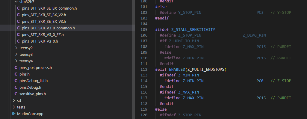
which says the Z_MAX_PIN is Suppose to use PC15 (which is PWRDET), the board schematic says that is correct.
so lets search for Z_Probe and see what pin that is set for …
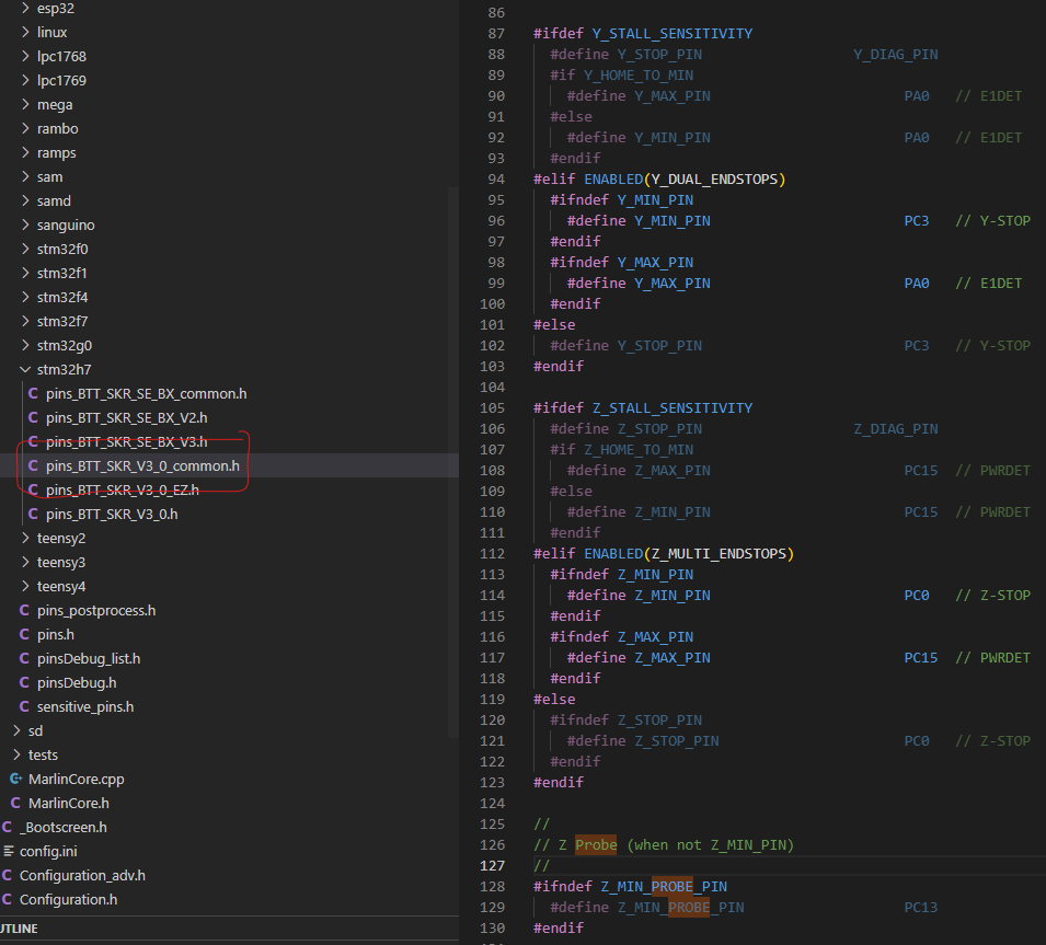
and PC13 does not look like its enabled, and would be using the actual PROBE pins on my board.
(after reading this i remembered that Zmin was used for the probe, but i am leaving it here as it was part of the discovery process for me )
So, again, just trying to do something here and maybe learn a bit more, but it seems that the PINS are assigned correctly, but somehow when using M119 command the Z_PROBE is assigned to the wrong part on the board.
Then looking around the pins config i found the one for the SKR PRO and although the layout for the file is different i was able to find where it defines the PINS for the PROBE and X_MAX_ (Z2) which should be located on the E0 pin
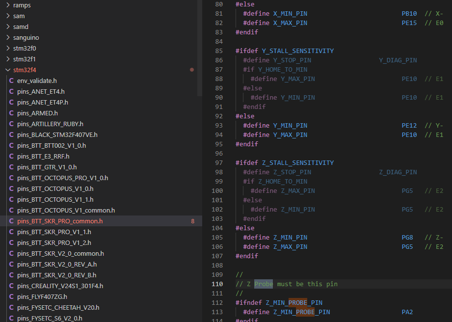
and they are defining the pins like your drawing
E0 or PG15 as the probe pin in the SKP PRO pins config is here
Transfering that define of X_MAX_PIN to my PINS define and i get
So it is setup correctly, but for what ever reason the line is not showing up as “active”
And here is where I have no idea, I am fairly sure it has been defined, but its not showing that it has. I am not sure how to make it show as active as its not ‘commented out’
I wonder if there is “shoot me in the head” emoji…
Let me rant for a second and say they should not be futzing with the pins file based on these dual x,y,z values. They should have just set these up to have useful names and let us pick that name when we set dual Z. /rant
I think you need to define that Xmax pin, and I would just do it in the pins. Just pull that #define X_MAX_PIN out of the if blocks.
I bet that works. Good find on the pins. If we get a second or third user with this board, we can all work together for a more permanent fix.
1 Like
I don’t really know what or how to do what your asking, can you give me picture to show me where I should be defining that pin?.
Its there but I just cant figure out how to make it not shadowed out. I understand somehow i have to call that define, i jsut dont know how…
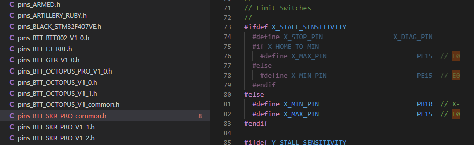
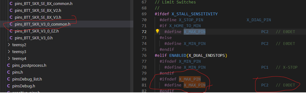
In pins_BTT_SKR_V3_0_common.h. on lin 68, make a new line there and put this on it:
#define XMAX_PIN PC2
That should change something. Maybe it will fix it.
The longer story is that:
#ifdef X_STALL_SENSITIVITY means, "Only do the next lines if X_STALL_SENSITIVITY is defined.
The #elif ENABLED(X_DUAL_ENDSTOPS) means, "else, if X_DUAL_ENDSTOPS is enabled, do this:
vscode thinks that x stall sensitivity is false in your config, and also x dual endstops is not enabled. So it shows those lines as gray. Because they won’t be used.
We need the xmax pin defined, and we don’t want to define x stall sensitivity or enable x dual endstops. So I want you to define the xmax pin outside of those if blocks.
1 Like
ok, it fails.
Processing STM32H743Vx_btt (platform: ststm32@~14.1.0; board: marlin_STM32H743Vx; framework: arduino)
Verbose mode can be enabled via -v, --verbose option
In file included from buildroot/share/PlatformIO/scripts/../../../../Marlin/src/inc/MarlinConfig.h:34,
from buildroot/share/PlatformIO/scripts/common-dependencies.h:29:
buildroot/share/PlatformIO/scripts/../../../../Marlin/src/inc/../pins/pins.h:720:12: fatal error: stm32h7/pins_BTT_SKR_V3_0_EZ.h: No such file or directory
720 | #include “stm32h7/pins_BTT_SKR_V3_0_EZ.h” // STM32H7 env:STM32H743Vx_btt
| ^~~~~~~~~~~~~~~~~~~~~~~~~~~~~~~~
compilation terminated.
Error: MOTHERBOARD is not defined in Configuration.h
=========================================================================== [FAILED] Took 0.84 seconds ====
I checked the Config.h files and its set correctly.
but it also fails if I remove the line, so I am going to re-download a new version of the file SKR PRO files and make fresh changes, as there is no guarantee that I have not messed with the files with my stumbling around in the structure.
1 Like
but we are super close now to getting another usable board, be it a bit hacked and in need of a clean up, but another board.so worth the time.
1 Like