Congrats on getting board firmware built and flashed!
The firmware process for the touchscreen is similar, but there are some more folders and files that are involved, including one folder with images that get used for the buttons. While the firmware for the board goes on an SD card inserted into the board, the firmware for the touchscreen wants the SD card inserted into the touchscreen itself. Main things are: several folders and quite a few files, not just a single firmware.bin file… and among those added files is an “ini” file that allows a nice way to edit settings and reflash without having to completely recompile the firmware.
Hmm, definitely not what’s supposed to be happening. Could you post pics of how you have the TFT wired to the board? And maybe some screen shots of or copy paste of the key parts of the TFT ini and firmware config files etc. I’m thinking we need @jeffeb3 or another of the firmware pros to chime in.
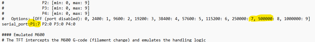
They have to match. 250k can be set in the tft to match the firmware. You won’t notice much difference unless you are playing gcode from the tft and you are using a ton of really tiny movements (like trochoidal milling or adaptive clearing).
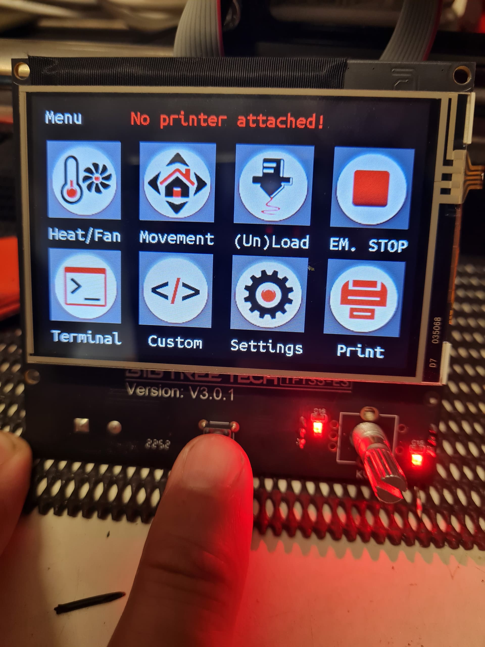
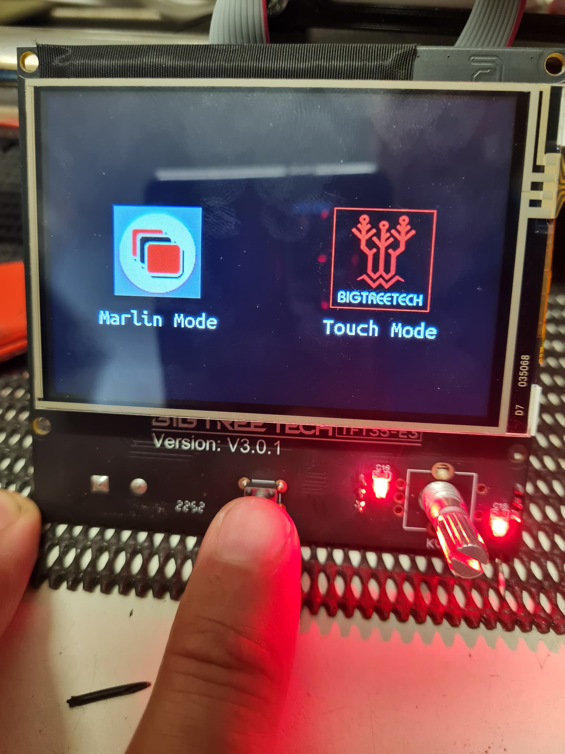
That signal is carried on the gray cables. You probably have one or both backward or swapped. If you hold the knob down for 10s, you can switch to marlin mode. Check that it is displaying a menu and not garbage.
The other possibility is the case for your screen could be shorting something or holding the reset button right on the edge of pressed.
Since it is swapping modes on its own, it is probably the gray cables.
Ok, let me clear that up a bit. when I set the the baud rate too 25k the any movement of the dial or pressing the dial makes the tft35 and by extension the board reset.
setting back to 115200 stops that, but there is no response to using the dial.
I will grab the code of the TFT35 (update 25/9/22) and pour it into VSCODE and see what the baud rate is in that. The firmware is clearly not happy, i did notice that the TFT35 is ver 3.0.1, but that should not NORMALLY make a big difference.
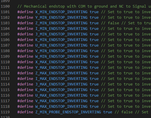
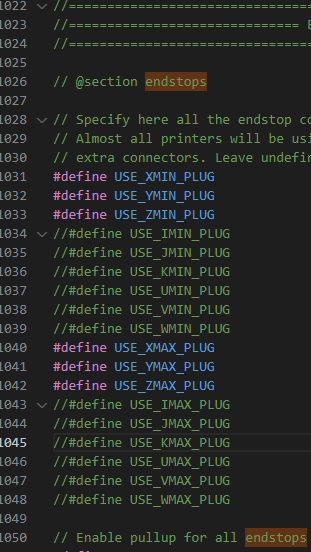
I dunno actually, let me have another look at the end stop section of the firmware…
ok here we go.
looking at my protoface picture the names are different, your right there is no ZMAX, which I assume is z2, but its clearly enabled in the code. That is strange.
Thanks doug,
I checked the INI front eh 25/5/22 update on the V1 site and it has the baud rate at 50k, so setting it to 25k would be ok, but 115200 is probably a bit slow. So next firmware load for the board i will up that to 50k and see how we go with that.
I have a 48v plug pack on order that should be here by Thursday, so i will be able to test the motors at that stage as well. But, well, I am not hopeful. I am sure this board will work with enough tweaking, but SIGH why cant it just work… lol. cos I brought the wrong board.
Well I was thinking I would love a zen table maybe I can use it for that…
Ok, I set the baud rate to 50k in the board firmware and just loaded it on to the machine, the knob is not re-setting the TFT35 and by extension the board anymore, BUT the same thing happens.
(i would load video, but the site does not accept them.)
so you boot the board (usb power atm, using the jumper on the board)
the V1 LOGO comes up
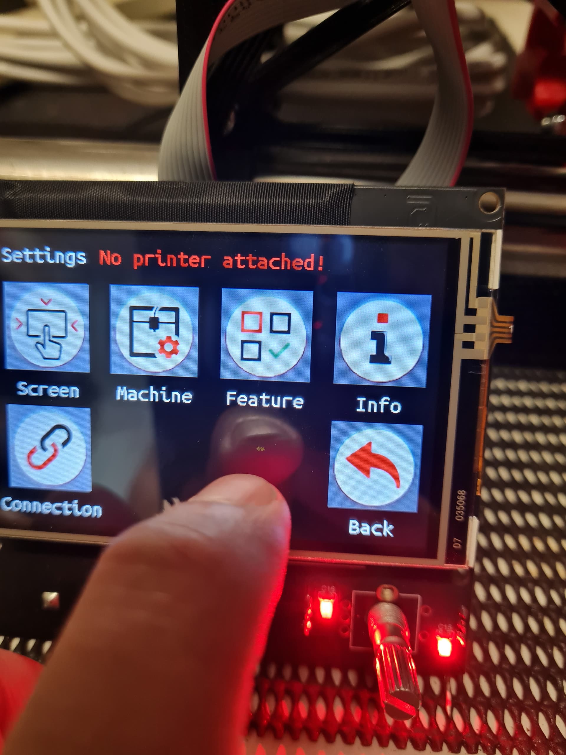
and about 10 sec later the TFT35 drops from the logo to the Grey button menu. I will add here that i am using the CNC version but it seems to be the printer version…
the touch screen does not seem to be damaged, the film has been removed, all the buttons are pressable, and doesn’t seem to be highlighting one button like something is pressing on it , also the knob / dial is as i would expect that unit to feel, moderate pressure to engage the click. it doesnt feel “stuck” or damaged.
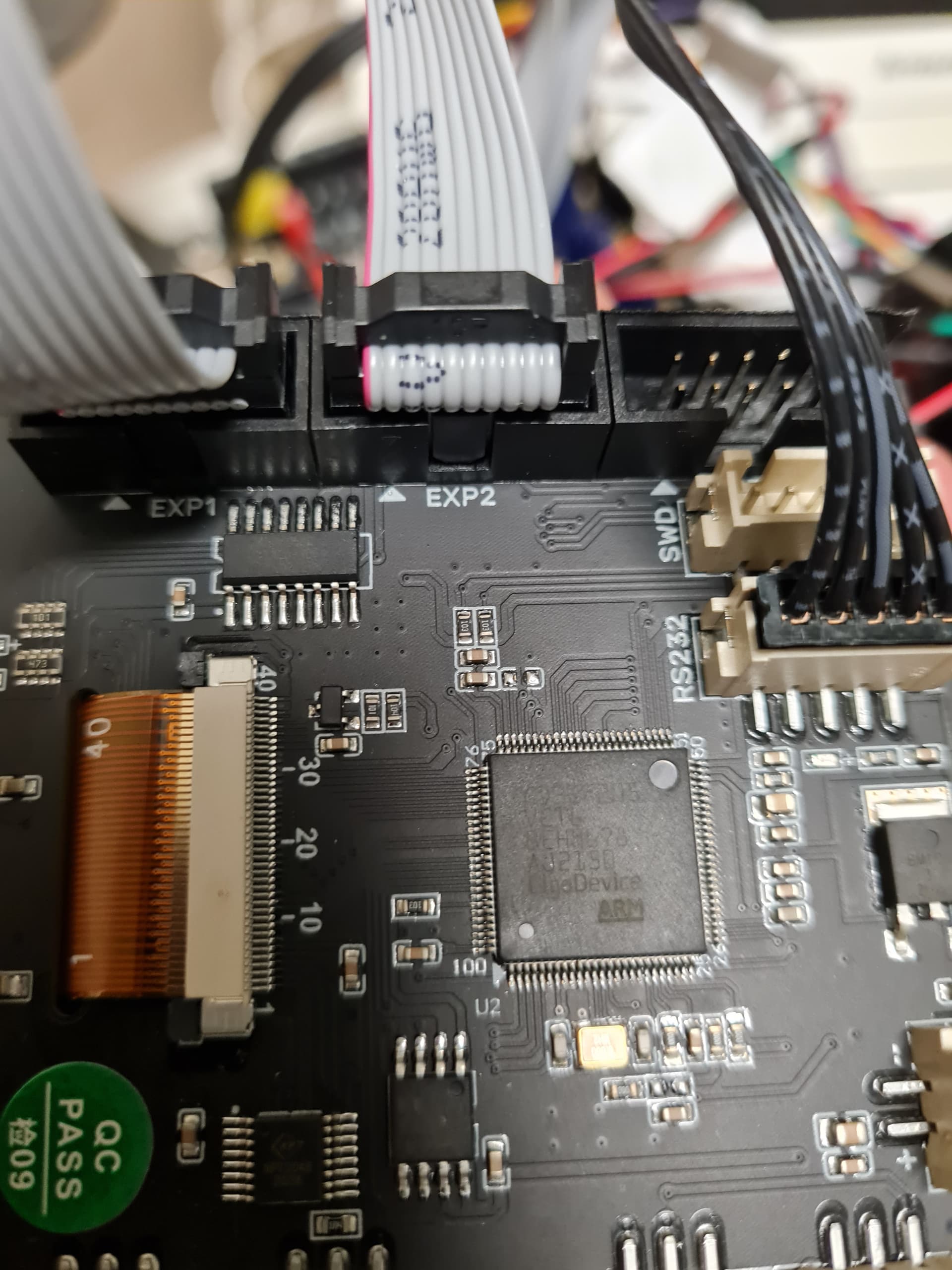
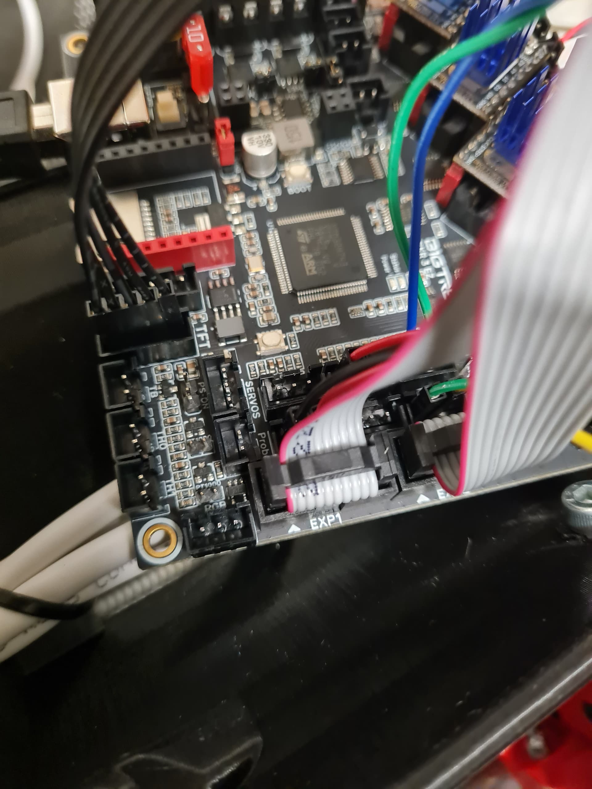
EXP1 on the TFT35 goes to EXP1 on the board
EXP2 ont he TFT35 goes to EXP2 on the board.
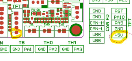
RS232 on the TFT35 goes to the board and is in this pin out
And seems to be in the right order with the 5v line at the bottom.
Also I just did a test and removed the back wires, the TFT touchscreen still works, the mechanical dial does not seem to do anything whether the blackwires is connected or not.
ok i have just physically swapped the cables
so pulled them both out at both ends and used the cable that was in exp1 as the cable in exp2 and same for the other cable with the same result, the screen works for 10secs, i can move through the screens forward and back and use all the buttons, but after 10 seconds the screen still returns to the “choice screen”
So its not the physical cables. pin out maybe.
Yep, removing those grey wires fixed that issue.
I can move around the interface and even press and hold to go into and out of MARLIN mode.
But I am sure its not connecting properly or the board is still screwed in that going to the terminal and typing M119 gets no response and MARLIN mode gets no response. I also still have the printer not connected.
I am not sure if not having the 48v power supply connected is the issue, but I am getting that on thursday, so I will be able to get that to happen on friday.
I just got the endstops so I will add those today so its as close as I can get.
Ok, one last post for now, i just downlaod a fresh copy of the SKR_PRO_DualLR2209 firmware and made the three changes only.
The different board.
the environment
the baud rate
then built it and loaded it
Nothing from the TFT35 using M119 at the terminal and no response from the marlin mode either. there is still the message across the top that says “no printer connected”
I will connect with protoface later today and check the m119 command but i suspect it wont work properly. A little disappointing, but I did buy the wrong board after all.
Did you check the baud rate on the tft settings? You can check from the tft display. You don’t have to change the config.ini.
If you have that message, don’t expect anything else in the tft to work. It won’t even try to send M119 in that state.
Those cables are needed for marlin mode. You had them wired wrong. The cables aren’t always keyed correctly. It looks like the two heads are in different directions in your last photo. That is abnormal.
There is no 50k. You must mean 500k. They need to match. 250,000 is the rate we use on all our firmwares. Now that you know the great cables were wrong. I would try that again.
It is also work checking. In the screen. In the settings menu. To make sure the baud rate is right. I trust that more than the config.