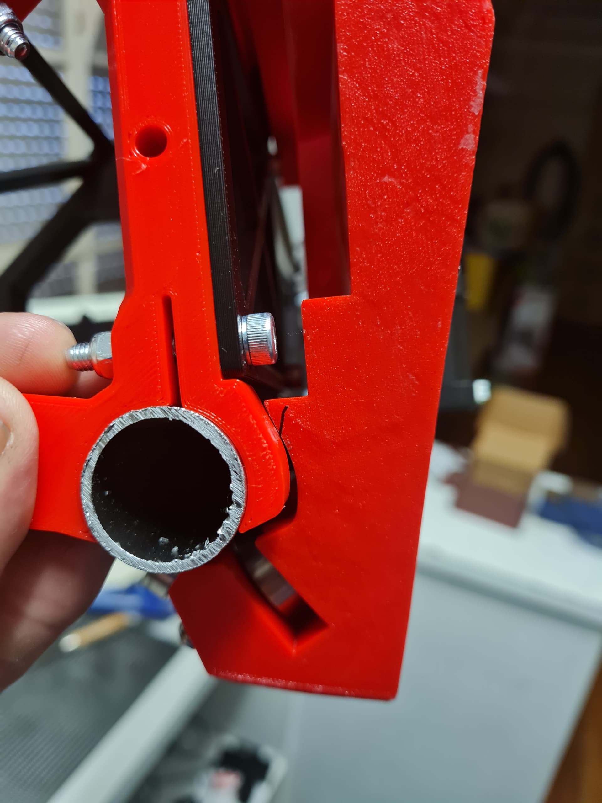
Tube
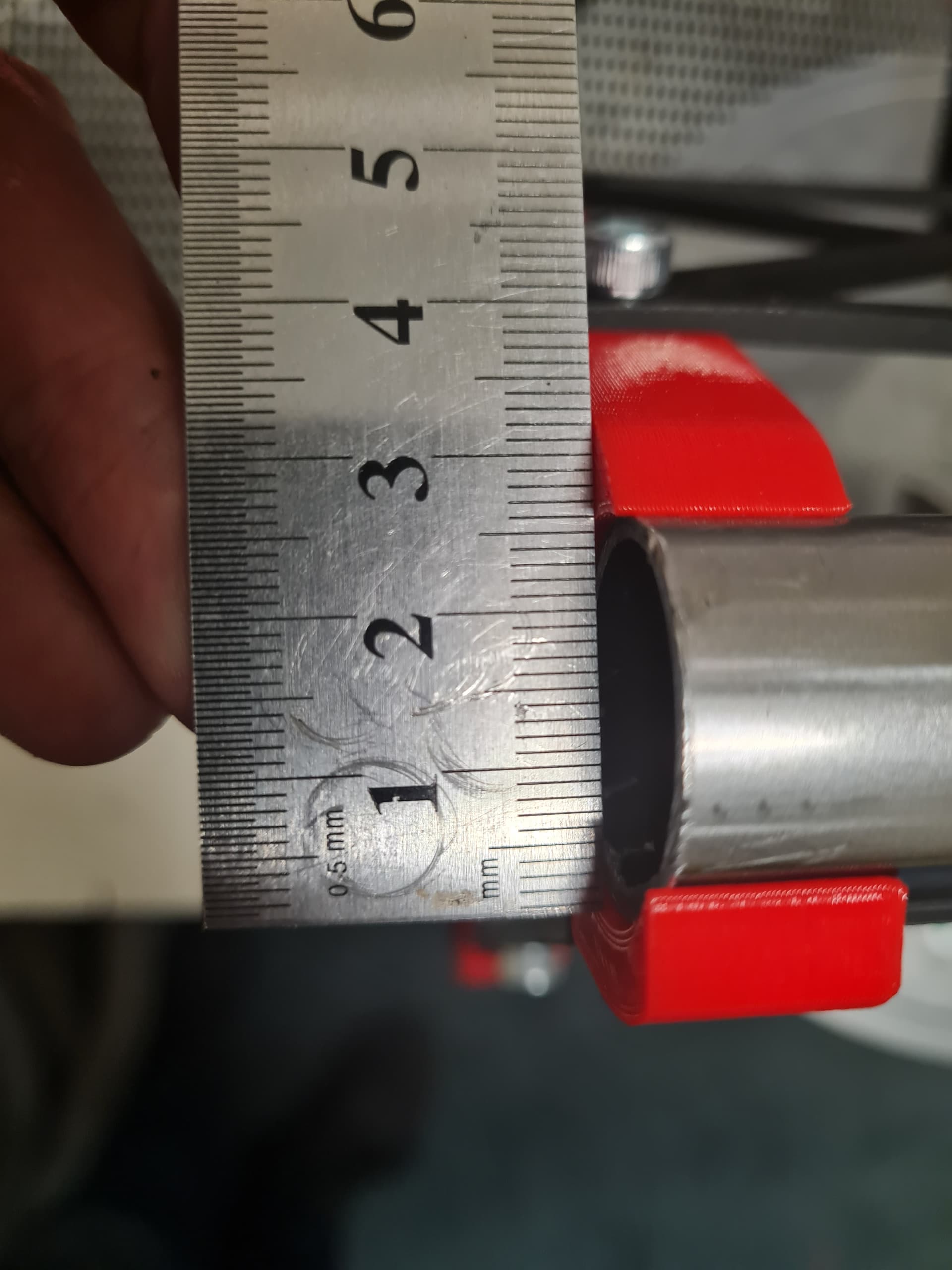
Better pick of ininterference
Have you tried loosening the bolts that adjust the core tension?
Yikes, you must have had it cranked down!
Well before Matt message I took to one of the braces with a file and was able to make it run smoothly.
But I will def see if there is any adjustment in the core i have missed.
MATT FOR THE WIN!
Yep I had over tensioned the CORE bolts. Loosened up the lower bolts and it slides past the braces perfectly.
Thanks Matt
LOL, well I didn’t read the instructions and just started putting stuff together.
And well if there is a bolt and bearing, i just do that up… ![]() That is my defence and i am sticking to it…
That is my defence and i am sticking to it… ![]()
Once you RTF, it does state to loosely put them in. SIGH. ![]()
So not much progress on my LR3 this week, i did a bit more pronting of the control board box, the LCD box and the makita router holders,
Processing: 16764173201326774947132118576440.jpg…
Although the LCD screen did come back into stock, so I snapped that up.
But not much else. I really need to go and find the wire i brought and put away safe… very safe apparently… so i can START the wiring.
Hopefull onnthe weekend i can get the WINGS made for my paulk table and grt to the point that unit rolls and i can make the obligatory brrrrrbeeeeeebuuuuuurrrrrrrrr sounds
Hi All!
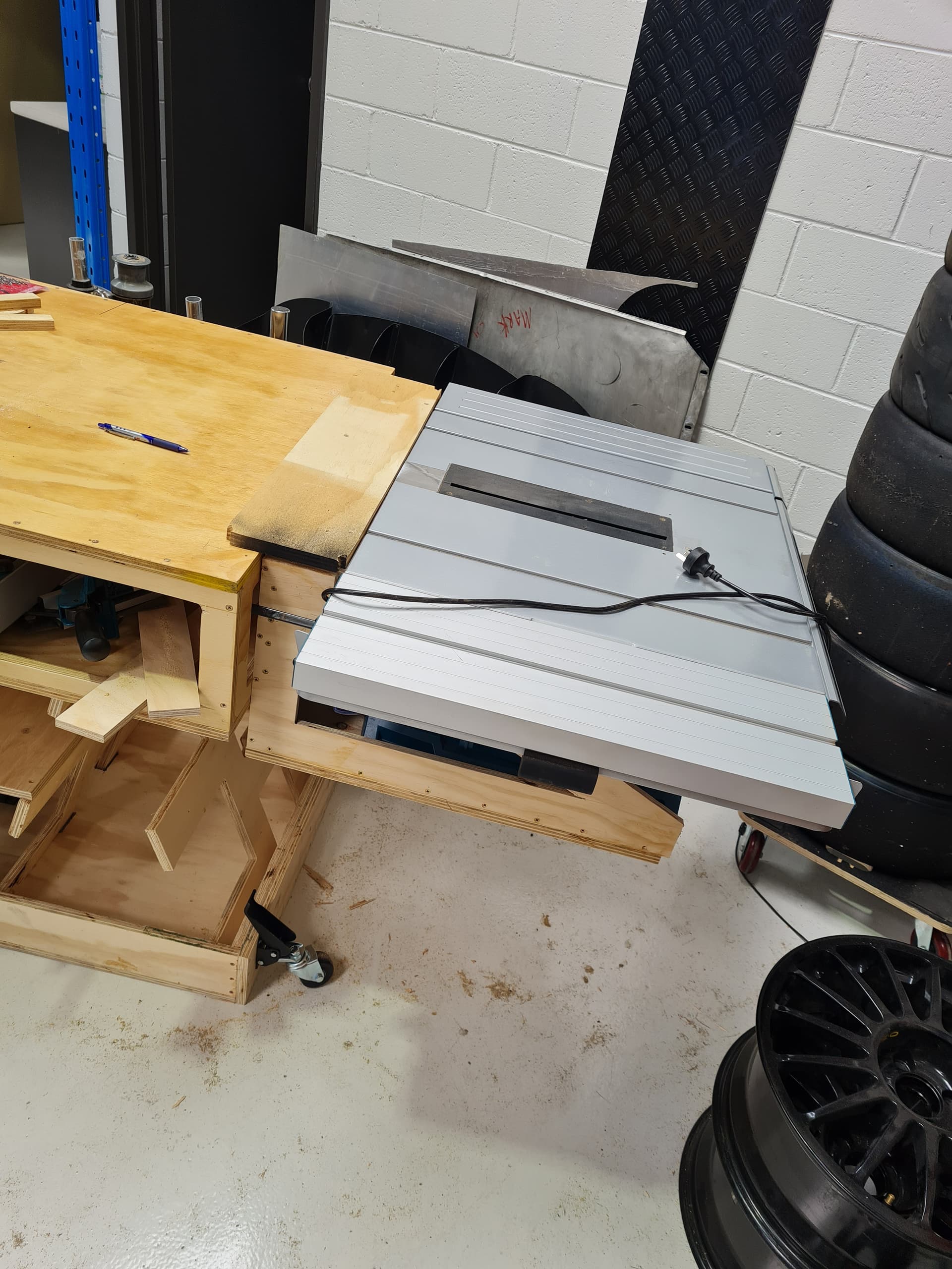
Ok, again not much progress on the LR3, but I did get a bit done on the table that I am going to use as the base for the LR3. As I have been saying its going to be a multi use thing as I have super limited space.
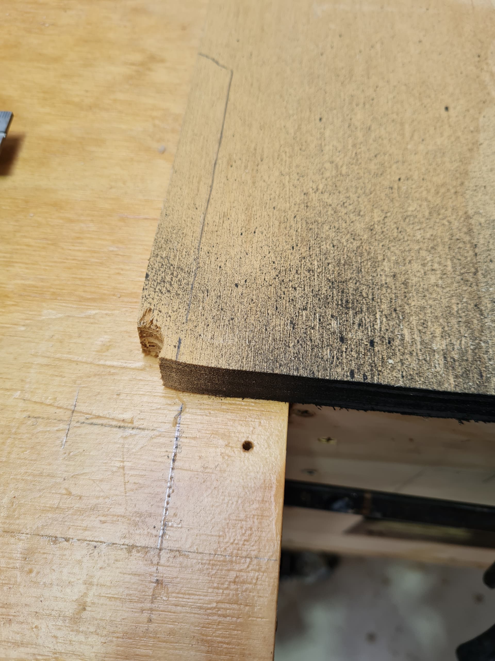
Eventually the LR3 will cut a series of 20mm holes at 96mm x 96mm and these “addons” will have 20mm dowel under this plate, that hook into these holes, the first section of holes is 32mm from this edge along that line (yes that bit of wood is temporary as the LR3 will cut the tope plate to size for the table saw add on)
…
I am going to be using the 20mm holes as locating lugs and possibly through holes for a spoil boards / vacuum table combo. I am not sure how this is going to go, as I will have to make them removable and i am not sure if once removed they will still be flat when reinstalled. I know this is a compromise, but the reality is that I just dont have the space for a dedicated table. I am hoping with how rigid the table is and the fact the vac table/ spoil board combo is going to be 16mm or so thick, it will be ok. Oh and the Vac/soil board combo will be bolted down to the bench.
LR3 wise, I finally found the wire I brought and put in that “SAFE PLACE”…
Now to find the soldering iron, its does not seem to bit in the same “SAFE PLACE” as the wire, so clearly i have several “SAFE PLACES” just in case…
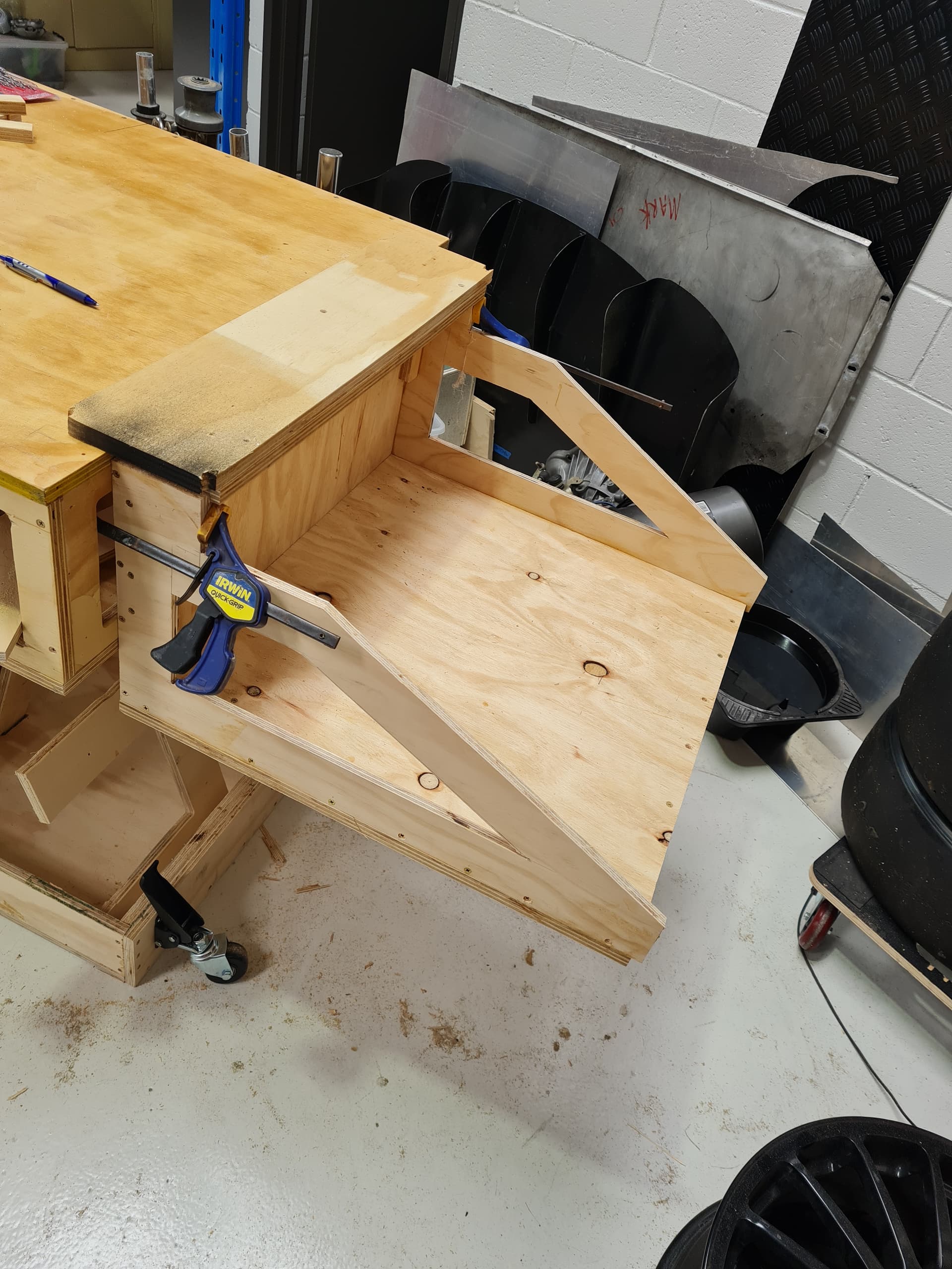
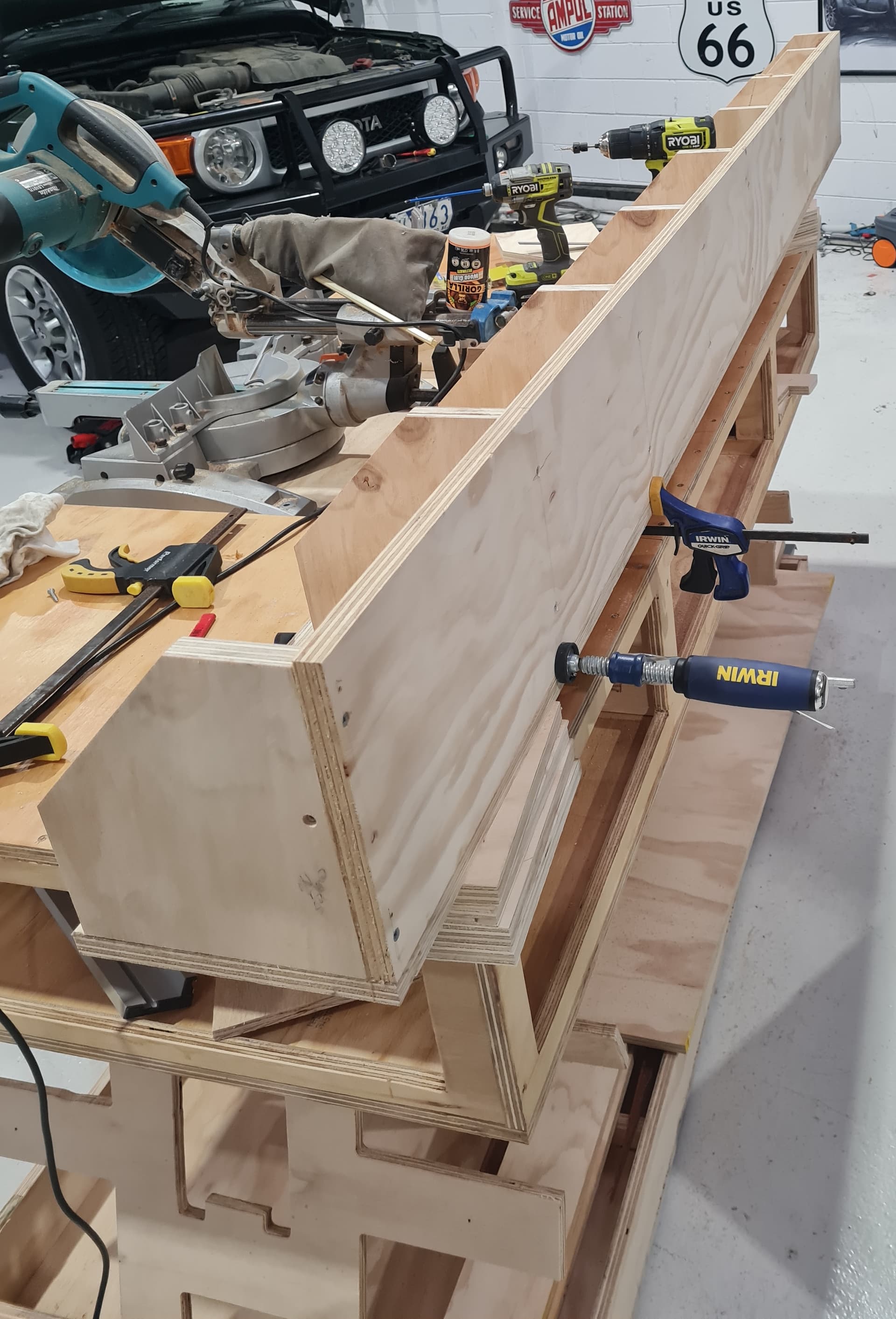
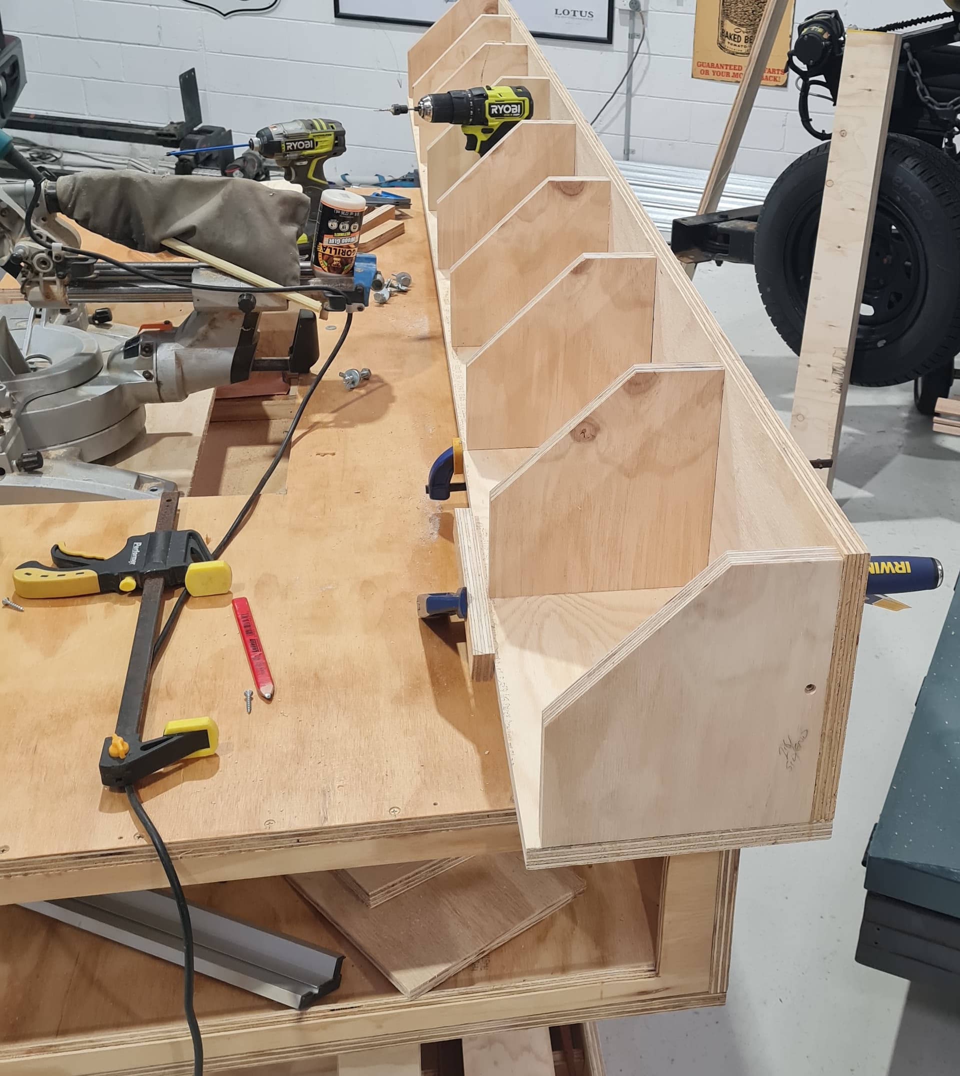
ok, a little more progress on the table for the LR3
I moved away from the full “Torsion Box” build for the wings purely for the weight of the boxes.
I don’t think that it will matter for the loads I am going to be putting on the the unit, once they are “hooked” onto the 96mm grid of holes at the top and then I am going to use a couple of hand knobs into the side of the actual torsion box of the table.
I only got one made, as I put some wood in another one of those “SAFE” places…
These wings will give me a full 2440 x 1220 sheet cut ability, but I am thinking of making a smaller set of WINGS as well, maybe only half the length of the bench, so about 800mm -1000mm long for the smaller projects as they would be FAR easier to swing around!
This smaller set of WINGS would also give the other end of the table to work on while its cutting.
Of course I would not be able to use it for anything too “disturbing” like using a chisel and hammer etc.
But maybe, a glue up station, sanding table or maybe an assembly area.
OK,
well this could be a problem…
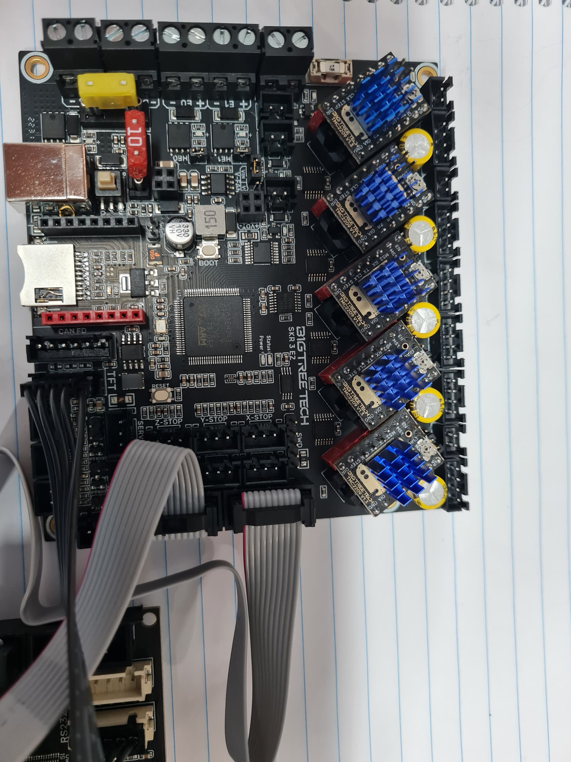
It seems in my haste to order stuff before xmas i have ordered a BIGTREE tech SKR 3 EZ
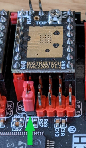
I am sure it will work, but the instructions on the V1 site say to put a jumper on the the pins for the UART the TMC drivers need, its located “under” the end of the TMC board,
But the EZ board doesnt really list a JUMPER location to do that.
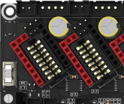
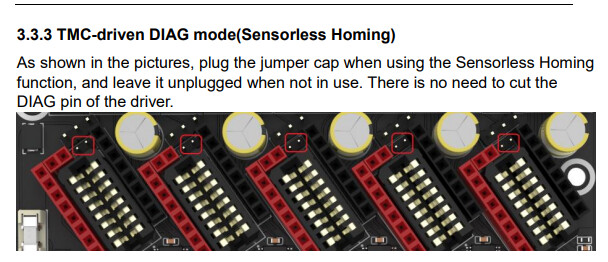
The manual lists these pins as the “sensor less” homing and to leave it unplugged if not using it.
Anyone able to help with this?
Am I on the right track with these jumpers (3.3.3 in the pic above)
Chris
-=-=-=-=-=-=-=-=-
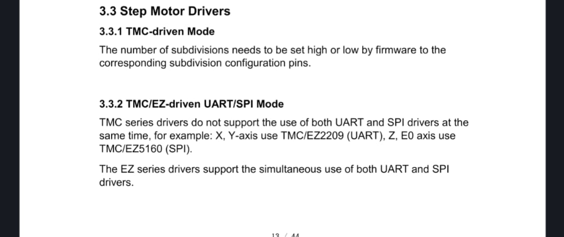
Manual for the EZ
I read the manual. I don’t get it.
The area under that port looks totally new to me too. What do the bottom of your tmc drivers look like?
This is my guess: TMC used to run uart and spi over the regular drv8825 pins. On the skr pro v1.2 (the one Ryan is documenting), that requires that jumper. Someone figured out they could add that weird 16 pin connector under the driver and not ask the user to mess with jumpers anymore. They are calling it TMC EZ.
So I guess you don’t need to worry about it.
You don’t want sensorless homing. So you can ignore that. The motor power is also a nearby jumper, so make sure that is in the right place.
The real trick is going to be getting the firmware correct. I would guess starting with the skr pro firmware and changing the board is going to get you most of the way there. Compile the skr pro firmware (from MarlinBuilder releases) without changing it with platformio. Then change the board type and see if it builds.
bigtree have new drivers coming out, or are out, that have edge contacts like the old game cartridges. So they had to move the jumpers.
Thanks @jeffeb3 Jeff, and thanks @barry99705
As barry said, under the driver is the “gameboy” slot for the driver and nothing else.
I was not planning on compiling firmware, SIGH, well that’s what you get when you rush and don’t check things. so now i get to figure out how to do that…
Oh and make SOMETHING that can hold the board as its too small for the box, hmmmm maybe i could use the temporary bracing as the design queue for the object to hold the smaller board in the bigger box… hmmmmmm
The boards Ryan sells are the best if you don’t like compiling firmware.
That said, it isn’t very difficult. There are a few dead ends that catch people. But the “yellow brick road” is pretty easy.
lol, well “hold my beer” what can go wrong…
Ok,
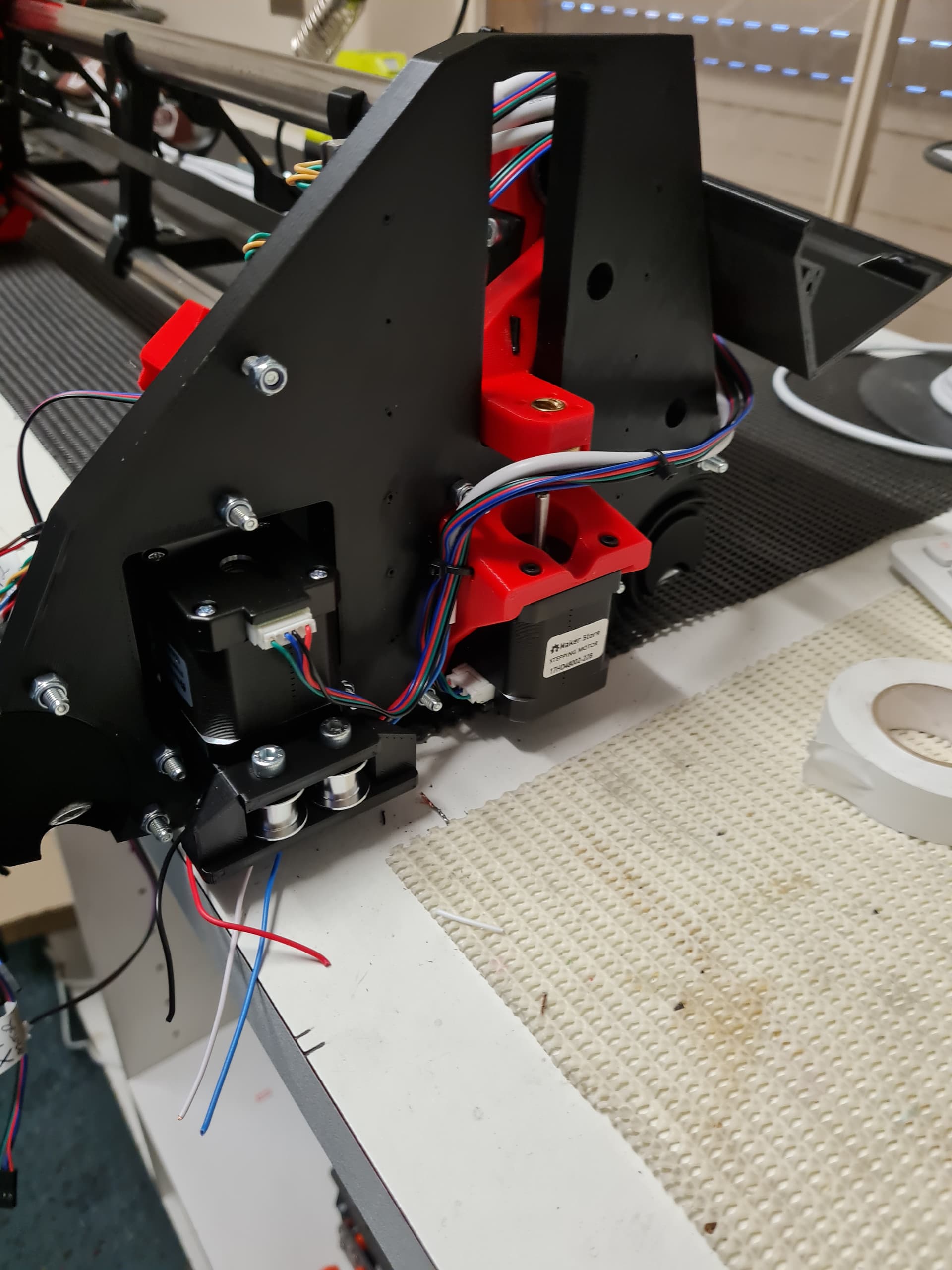
it was really quite at work, so managed to get the LR3 all together and wired up, well mostly wired up.
Waiting on the mirco-switches, cos I was not happy with the ones I ordered, also I need to go the local geek shop and grab some tiny heat shrink and some breadboard / Hook-up wires so I can solder them onto my end stops etc to make connecting then to the board easier.
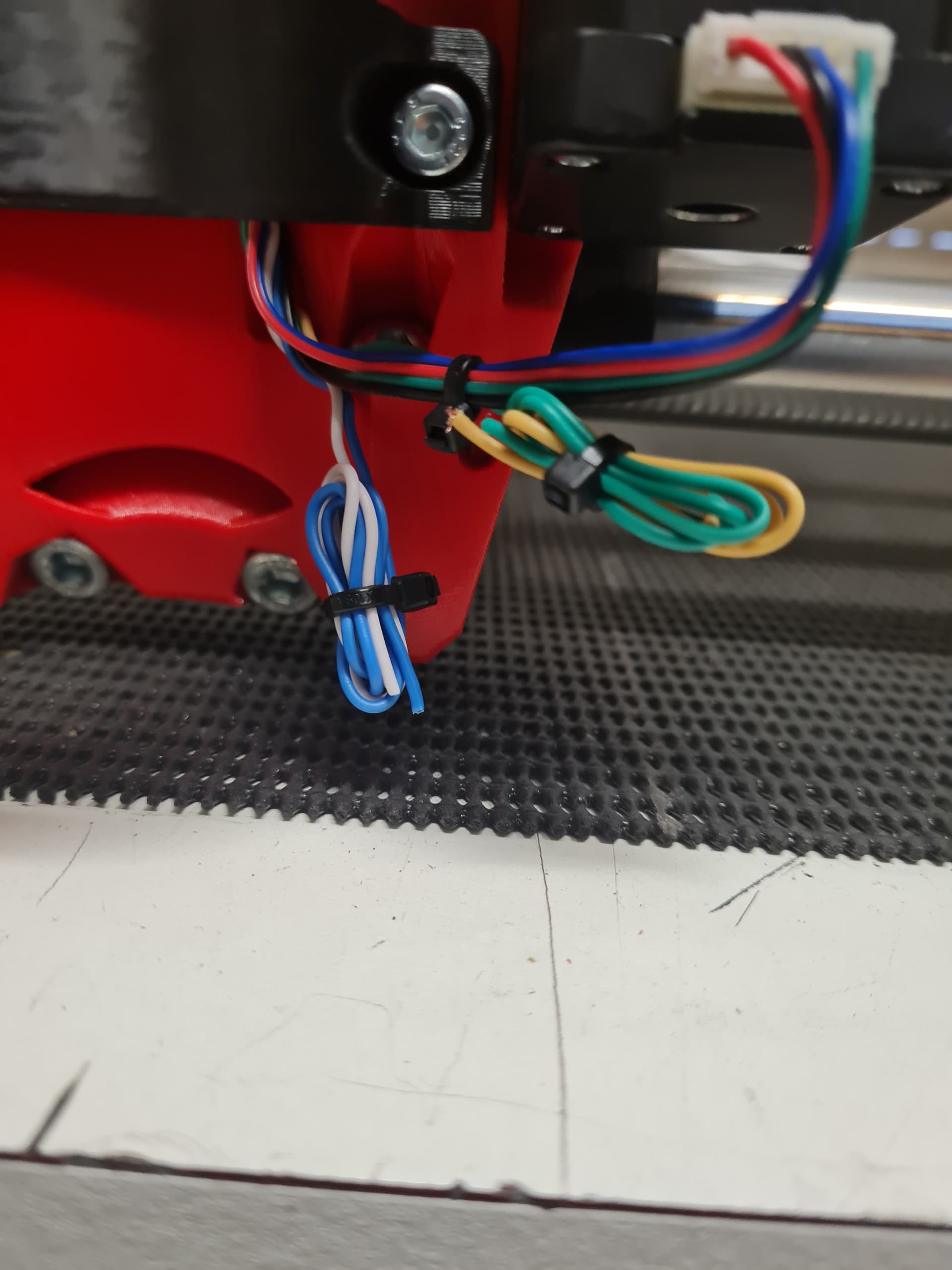
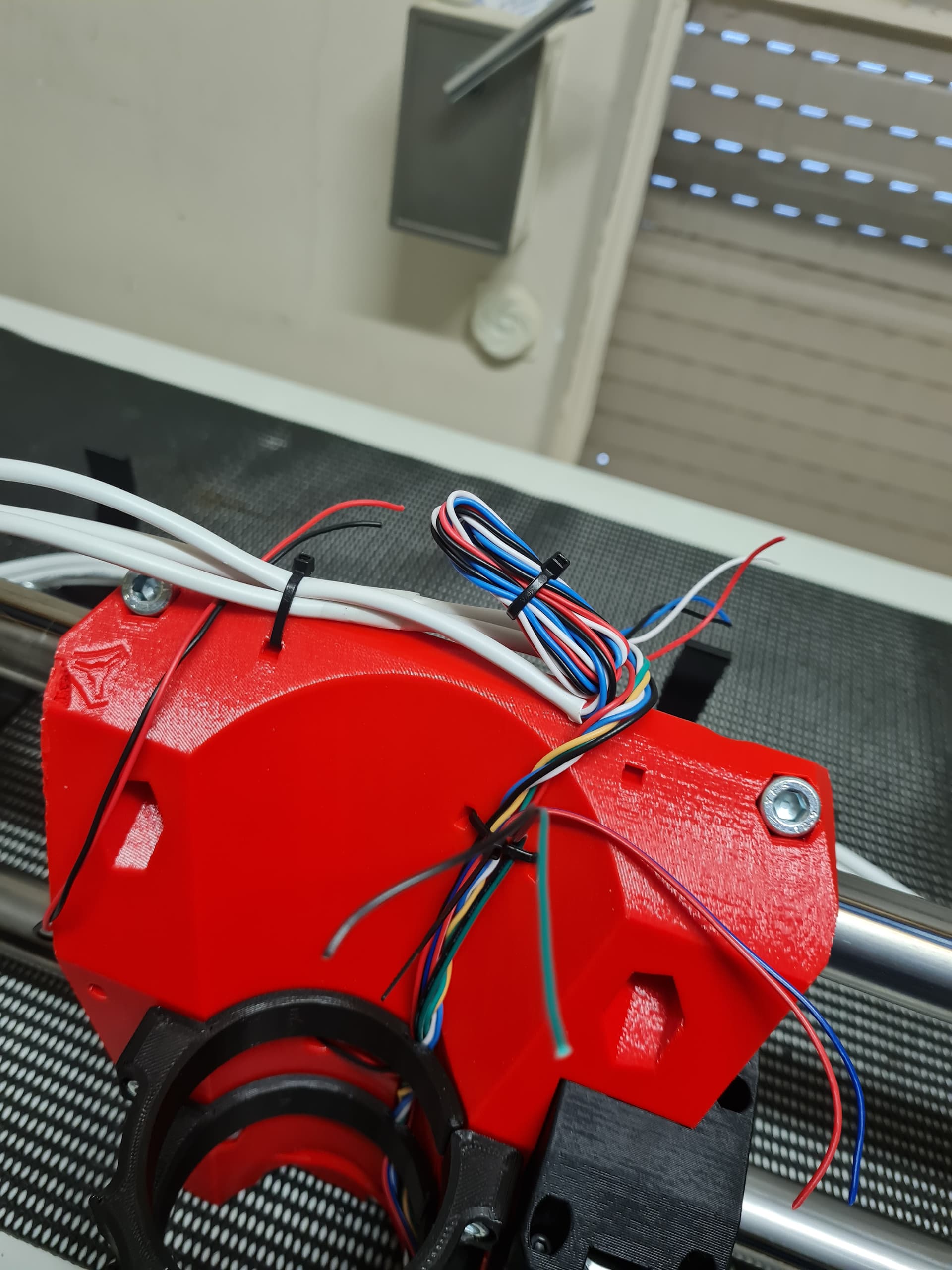
After reading and seeing some installs I ran few extra wires for a probe, (Yellow/Green) and light under the carriage (White/Blue)
and then a whole extra 4 wires cos why not.
I even made the obligatory robot noises once the thing could slide.
@vicious1 sorry not posting that… I sound like an idiot enough…
LOL
ok,
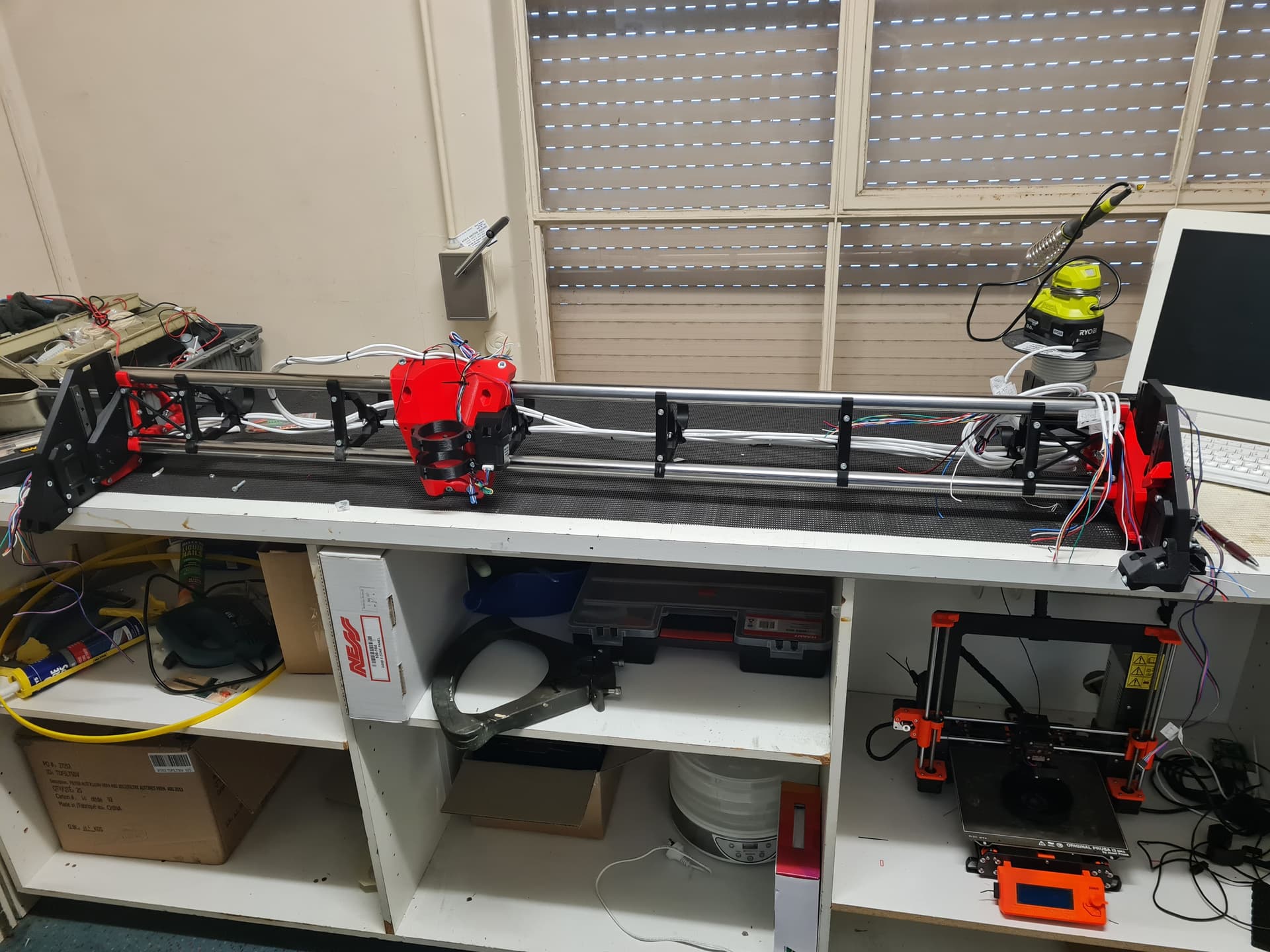
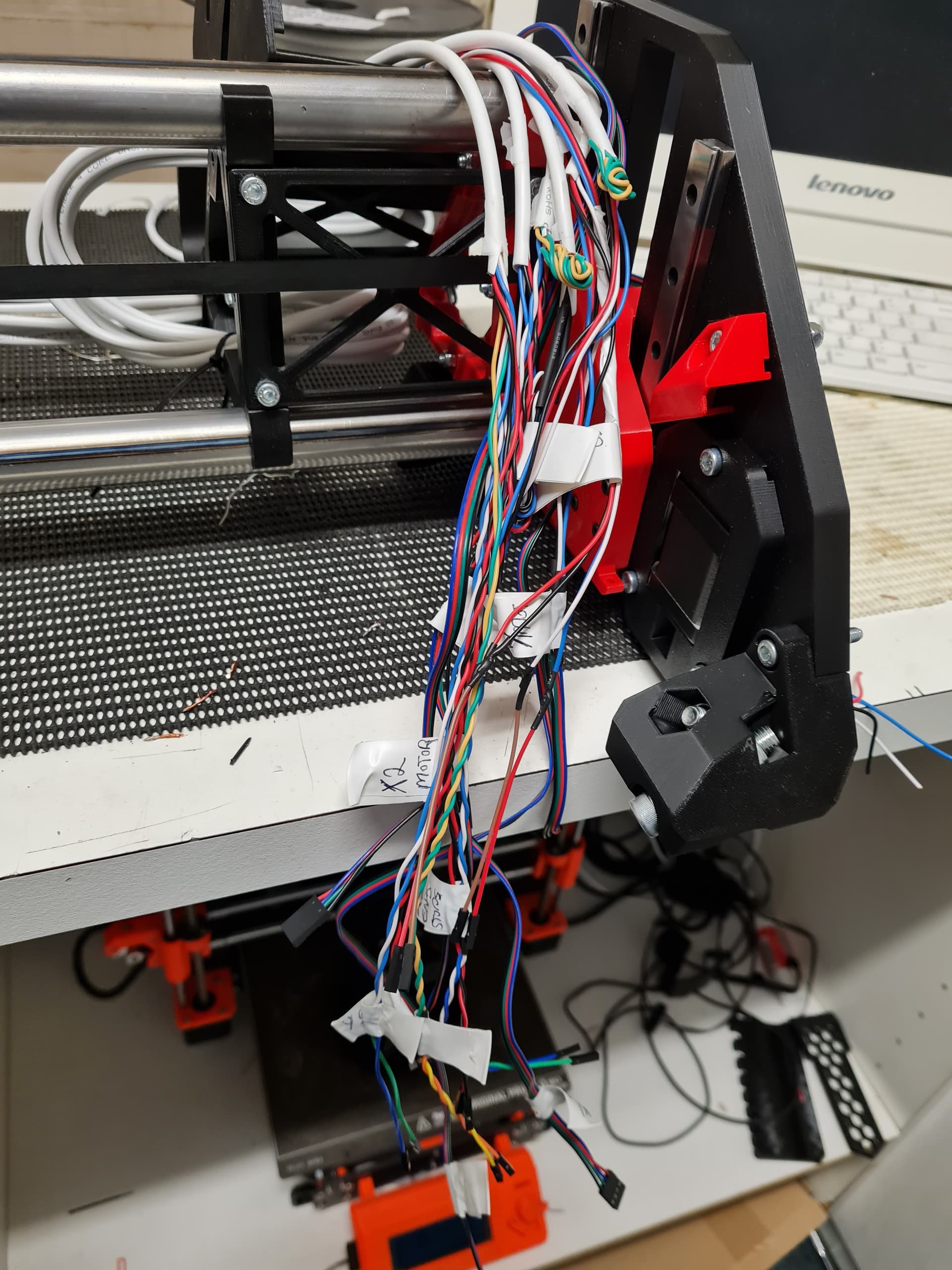
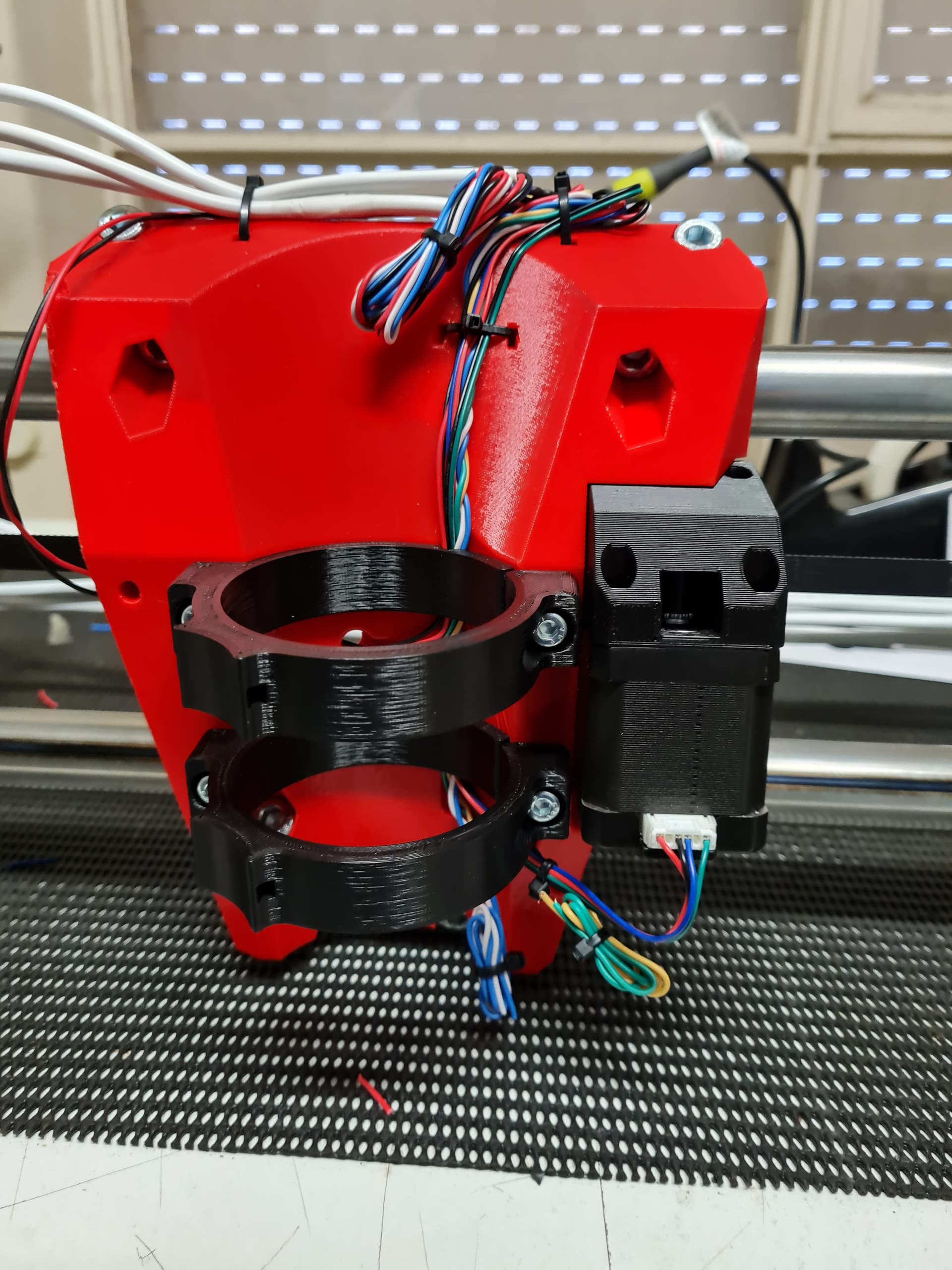
Today I managed to get all the end stop and stepper wires extended, run and tied down.
I am still waiting on my replacement end stops, so actual end stop end of the wire are just sitting waiting to be soldered to the end stops. (i prefer soldering those wires, rather than the crimp terminals)
Also now looking at the photos i have forgotten to put in the X1 (controller side ) Z end stop and bring it back to the controller. So another job for tomorrow…
I also added the Y belt in and made the obligatory robot noises sliding the carriage back and forth for longer than would be considered sane…
It seems that I only have one Z End Stop holder for some reason, so looks like I will have to fire up the PRUSA for a round of RED missing parts. (also somewhat lucky that i decided to run a 6 core to have a spare pair over that side of the machine… ![]() )
)
So tomorrow, might see the board wired up… you never know…
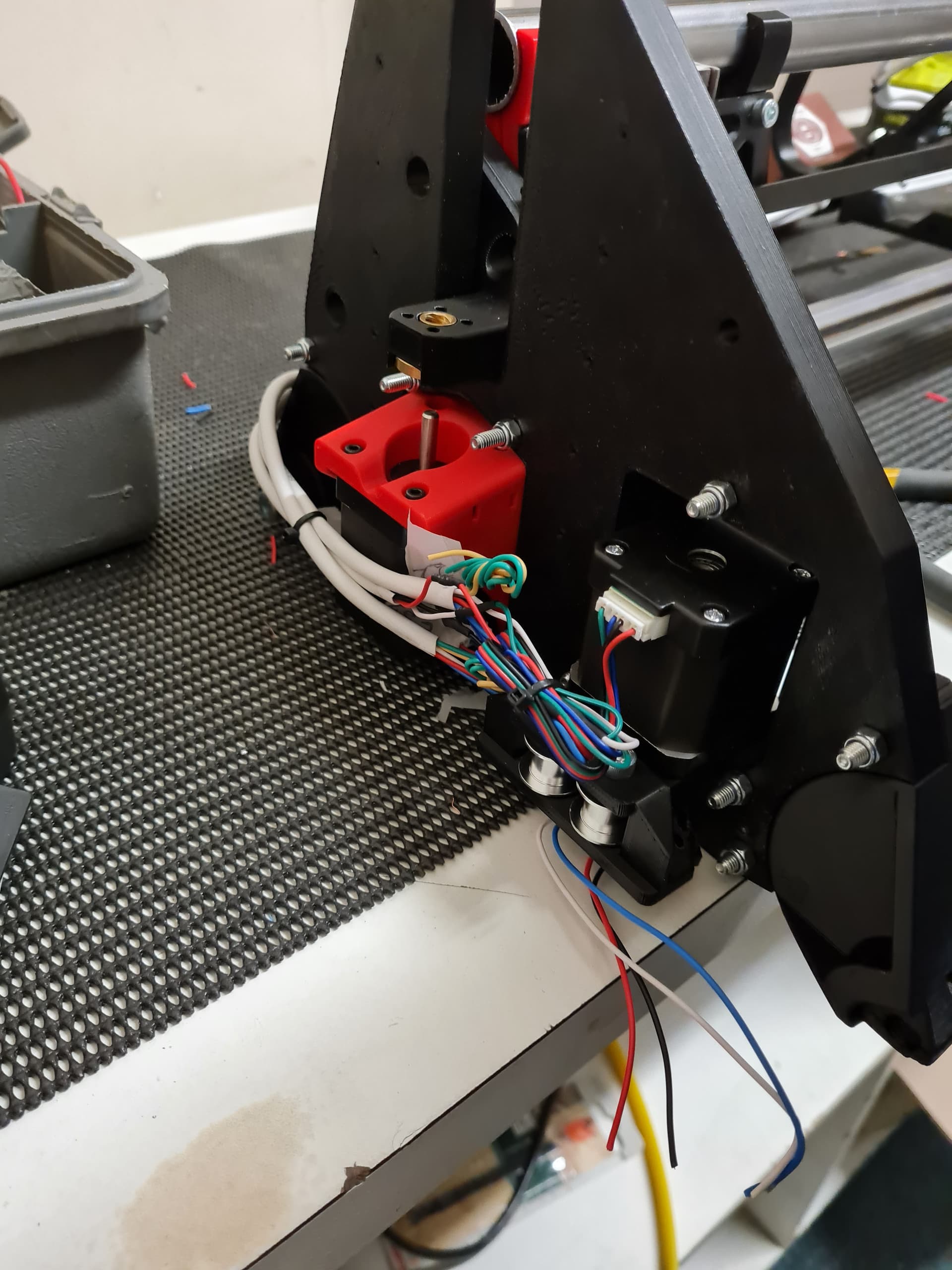
Looking at this photo…
Take a look at the Y belt motor holders. There are 2 small slots in the mounting surface that you will see see directly below the Z end stop switches. This is the provision to get the wiring through past the motor. You should find that the wiring goes a little more neatly using it instead of passing the wide under the YZ plate, and it’s one less place that the wire could potentially catch on something. It definitely helps keep it clear of the moving parts on the inside of the YZ plate.
I’m enjoying following along! Looking good!