Exactly! Why I love 3D printing so much.
1 Like
I was actauly thinking of adding a switch inline with the wires to the LR3 so i can use it for clean up, so probably going to have to do more protyping for that holder.
But that is why we are all here. A 3D printer allows us to build these CNC’S
LOVE IT
2 Likes
Software engineering and CAD both scratch a similar itch. Being able to just create something is an amazing feeling. Even if you look back at it 6 months later and cringe (that just means you are learning).
4 Likes
Between the 3D printers and the CNC, I love that something that didn’t exist anywhere in the world except in my head yesterday is a physical object in my hands today. Sometimes idea to object is even faster, even if sometimes it’s a few days of printing and milling…
4 Likes
Greetings,
l am in the planing process of building a yacht 43’ and starting a 54"X120" CNC LR3 is it possible to get a copy of your LR3 built list. I have to source the parts from several companies. The mail service in my country has a mind of its own.
Good luck with your repairs
Hi Sid, welcome!
As i am in Australia, unless you are here, then my build list is nit that different fron the one posted by Ryan.
The only major difference is the board and that was purely by mistake. So i have to make it work.
If you let us know where you are we might be able to help.
And if it helps, after the trouble i had getting parts, if i had to do it again i would just order them from V1.
3 Likes
The joy i get from being able to create domething like the fitting on rhe VAC hose, like you said creating something from nothing is pretty big.
It dopamine rush i get from getting that idea from and idea, through itterations and now be able to use what ever i was building is why I do this.
The fact i am building a CNC to help me buold other things is just bloody cool!
5 Likes
Ok, so (lol, not so) weekly wrap up.
I brought the vevor router and it comes with a 3/8" collet and a 1/4" collet. Check ![]()
I brought some new end mills, up cut, down cut, 1 and 2 flute varaents in 1/8" CHECK ![]()
![]() WAIT, hold on.
WAIT, hold on. ![]()
yep I brought the 1/8" endmills, SIGH.
Ok, scrambling here as I REALLY want to run the LR3 on the weekend and cut the boards to for the gantry. So talked to the guy i brought them off, Adams bits, and he was willing to return them or sell me a 1/8th collet that is designed for the Makita. BUT he is over the other side of the city and not open on the weekends. DOUBLE SIGH.
Right, so I found a retailer over near me that sells endmills, and they are open on sat morning & they are nearly triple the price of Adams Bits, but I can get them for the weekend. So looks like I am good there.
But I have another question, they had this surfacing endmill.
Diameter 1-1/8
Cutting Height 1/2
Shank 1/4
Overall Length (L) 1-13/16
Max RPM 28,000
Flutes 3
AU$50
Clearly this is designed for surfacing as it says it in the name, is this tool a MUST HAVE to surface the spoil board, I ask that as it seems like the “overhang” from cutting down the limits (due to the size of the cutter) seems like a good idea. Again a slightly stupid question, but can the VEVOR/Makita spin this? I know i can take very small slices / Stepovers, but just wondering where the limits of the VEVOR/ Makita power plants are?
Second Question:
regarding the surfacing operation, this is how i see it working. (after cutting the boards for the gantry)
- Zero X & Y
- Drive the head to the farthest point X & Y before crashing (minus a mm or so.)
- Read the TFT to see what the LR3 thinks the distance is.
- Check that for interests sake ( as i assume you will see if the step count is out on the boards.)
- Create a square in something that size
- Import that into ESTLcam and then
And that is where I am stuck, ESTLcam does not seem to have a surfacing operation, it has: Inside, outside and pocket, but they “follow lines”. The milling basics does not cover this, but reading between the lines do I essentially create a big rectangle 1mm smaller than my bed and then create a huge pocket? Remembering that I am planning on using that surfacing bit… If i can…
I have and have used a 1" surfacing bit in my Makita. It should be able to manage.
Be aware that your tramming needs to be excellent. If you get scorching in one direction, it is probable that the leading edge of the bit there is a bit high. The leading edge cuts as expected, but the trailing edge rubs, and the friction causes scorching.
4 Likes
great explanation, thanks!
In addition to Dan’s excellent advice, I would add: the Makita routers are air cooled, and while I don’t know if your VEVOR is or not, if it is air cooled, consider: The rotation speed matters both for cooling and torque. You can relieve strain by reducing step over, but also by reducing depth of cut, and I lean toward the latter. If you use some tool like GWizard Calculator to find out what RPM speed to operate the router for the surfacing job, because larger diameter bits mean slower RPM speeds, my knee jerk response early on during my first surfacing efforts, led me to reduce RPM speeds. What I should have done was increase feed speed to achieve being able to leave the RPM speed up, both for torque and cooling. And I unwittingly was going deeper and deeper, because the middle of the MDF was higher than the outer edges, and my depth each pass (I was doing a linear zig zag, not a pocket) eventually got too deep. At this point I literally burned up the Makita router. It was not moving fast enough (RPM) to be in its power band for torque, not moving fast enough (RPM) for the air cooling to offset the heat, and the too-deep cut combined with not enough feed speed meant I had slowly created an inferno inside the router. I was able to pay Makita to repair it, but they said I really toasted it badly, almost beyond repair. Another tip: from time to time, check the steppers and router / spindle to make sure they are not super hot. Ideally one of those point and click laser thermo readers. If not, even low tech by “almost touching” and perhaps carefully (i.e. quickly) touching to see if the temp is getting crazy, at least until you get a lot of cutting under your belt.
You can just create a big rectangle and tell ESTLcam you want to pocket it. That will lead to a spiral pocket path. The challenge with the spiral is that if your router axis is not perfectly perpendicular to the table surface (bit’s cutting plane is not parallel), then you will get what Dan warned about: perfect cut going on one side of the spiral, and burning / sledding on the other direction of the spiral. Since my LowRider 2 was not trammed real well (and I’m now on LR3 and I think its better, but anyway), back when I was surfacing with LR2 with tram issues, I only ever really had detriment from the tram deficiency when resurfacing the spoil board. So my easy out was to switch to a linear zig zag, instead of a pocket with a spiral. I will attach an SVG of a zig zag for resurfacing a full sheet MDF. It was created in vector editing software called CorelDRAW. I will also include the ESTLcam file in which I turned the SVG into a cut job.
2023-04-19 Spoil-board X-axis 49x97 approx 0.75 step-over (approx 75% overlay).zip (10.4 KB)
1 Like
thanks heaps to all of you!
Doug, i wont be able to use that as my cut area is only 1220mm wide and 510mm deep/long.
So i will have to create that same thing for a board my size using a vector or a dwg file from something like 360 or onshape.
You can resize that SVG using the free vector editing software named Inkscape.
1 Like
thanks doug!
Ok, l hate it when i have to adult.
So i got up early and got doen to rhe local specailsist woodworking store and $200 later i get 2x 1/4" bits and rhe surfacing bits.
But that is where the fun stopped, i had to put the finish coat of varnish the hatch on the yacht and then add the hatch frame.
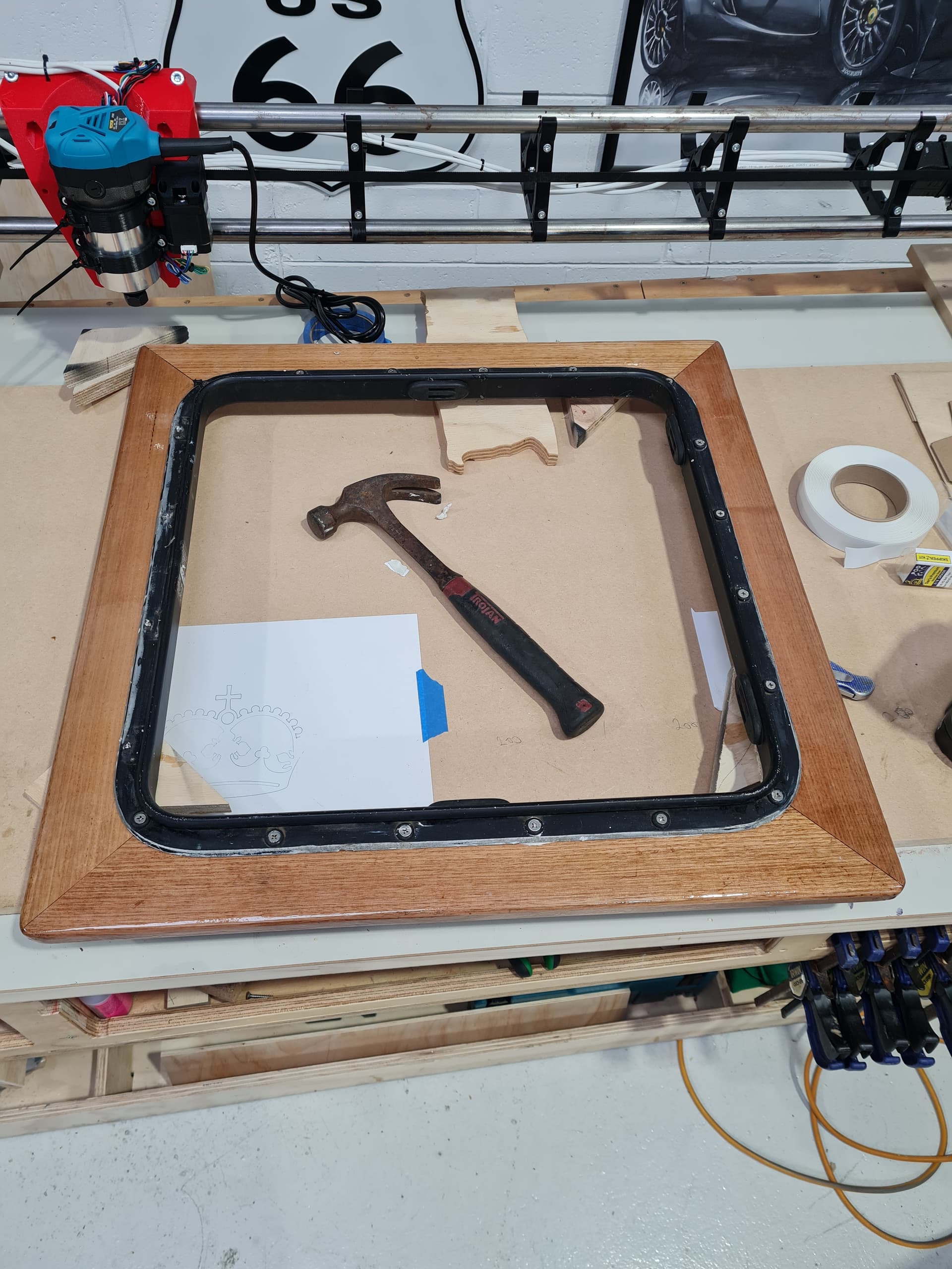
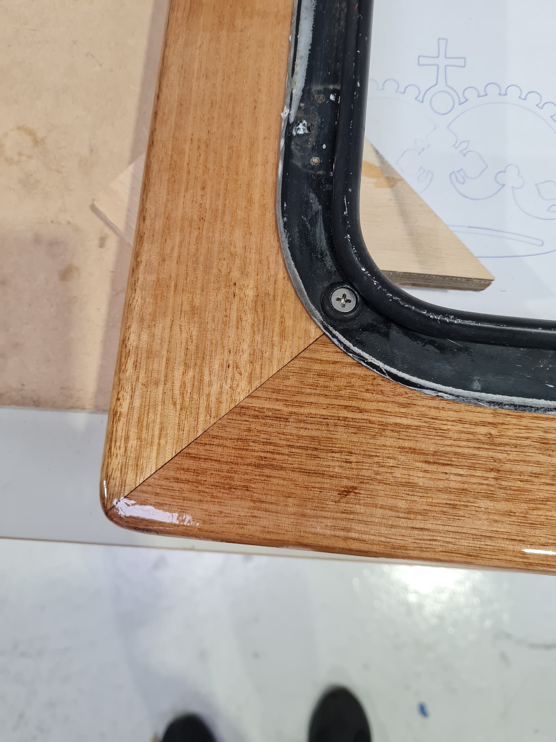
Tasmanian oak, epoxy glued and coated in thin epoxy. The 10 coats of varnish.
Not my best work, but i am not really in a shop to do fine detail, so i am pretty happy.
Then take that done to the boat and test fit, as melbourne was supposed to have a crappy weather day, but as it typical for melbourne, the beautiful out. Cold ish (for us) but blue skies and sunshine.
So had to do some more weather dependent tasks and some work on the yacht. So was not able to play!
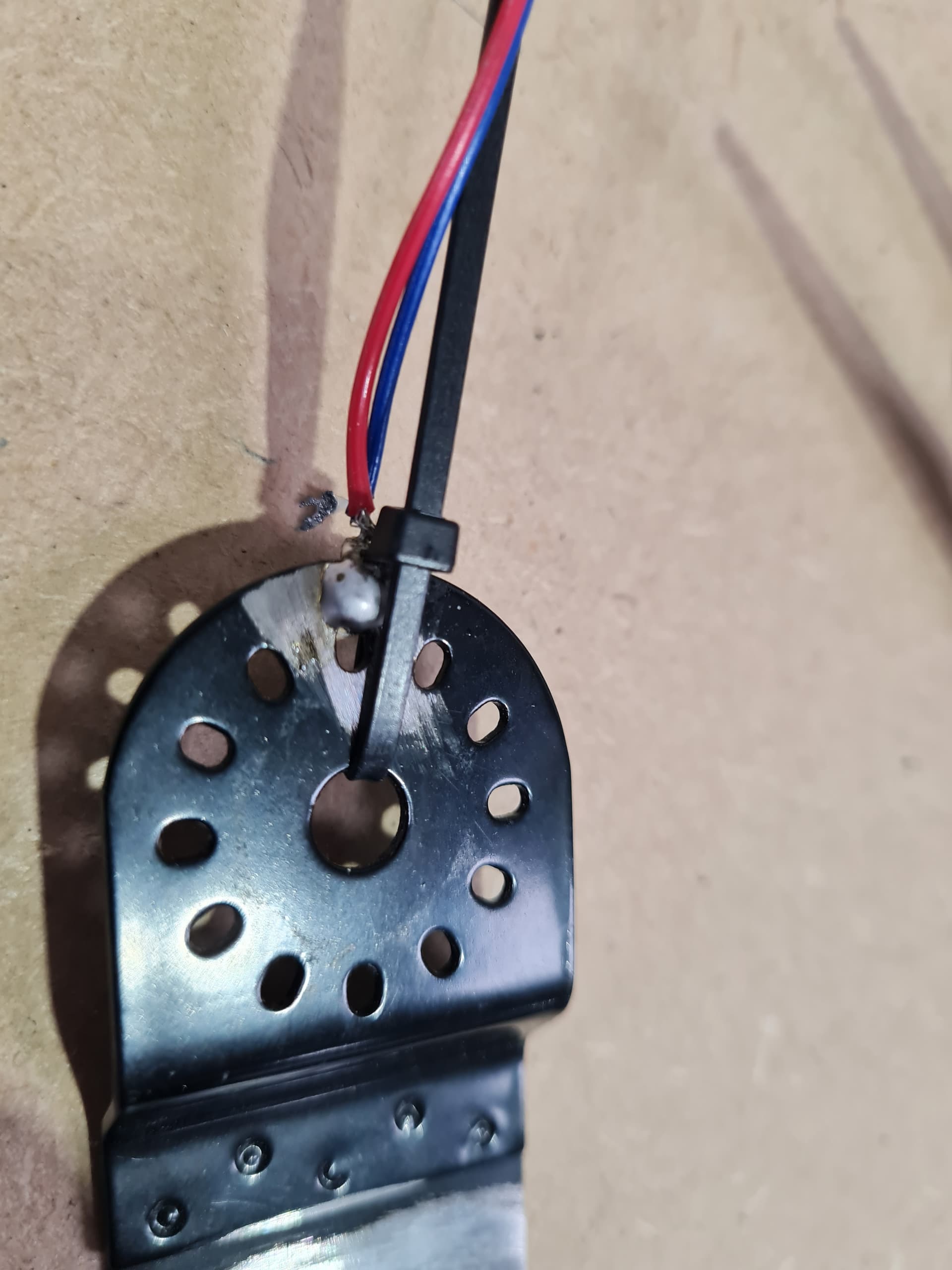
But i did get those things out of the way and decided to work on the touch plate. I had a bit of a good idea
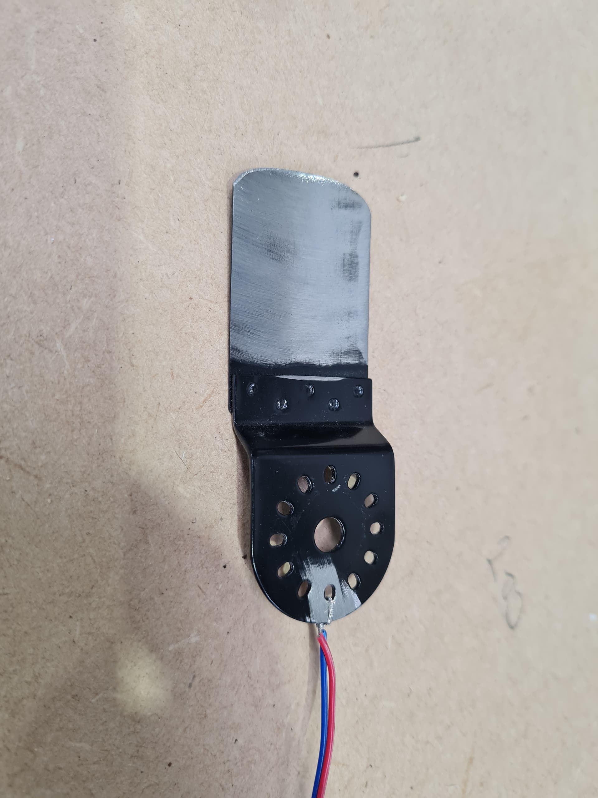
that is a somewhat cheap and used oscillation tool “bit”, it was powder coated or painted, but a little love with the flapper disk and i have a nice touch plate. As you can see i soldered the connection to it and here you can see i used a zip tie as support for the wire join
Throw an excessive amount of electrical tape at it and you get
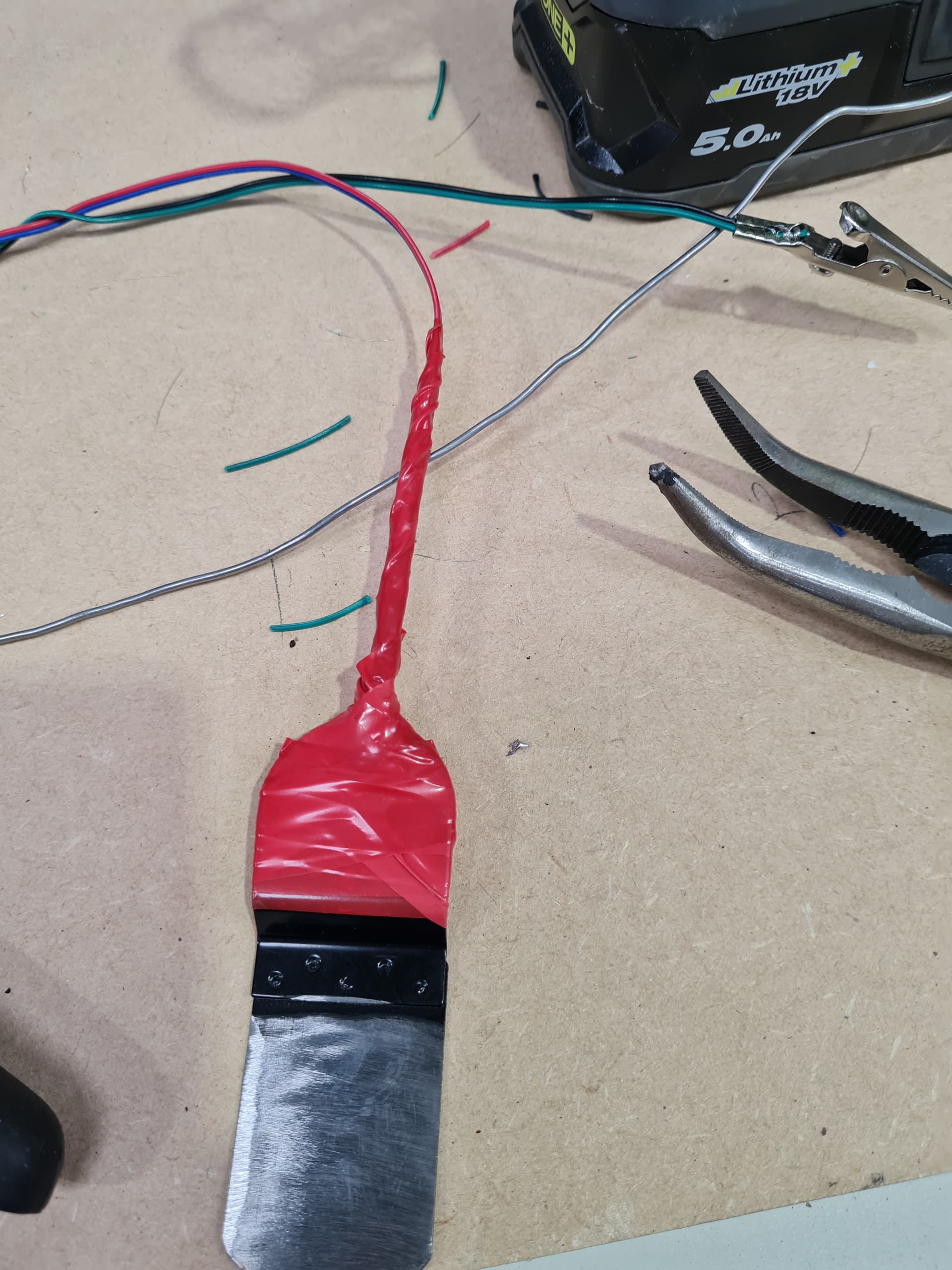
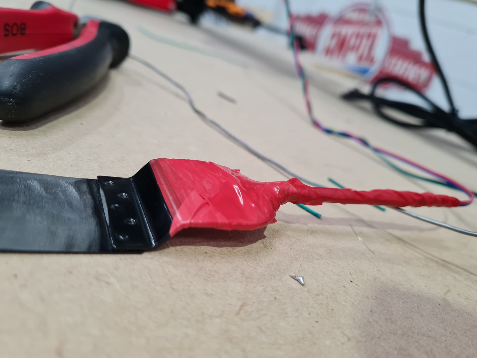
Like doug, i rhink it will live here, but time will tell.
I would not mind to mod the core and implant some magnets up there actaully…

So not bad progress, i want to go and check the wires on the board connectors, i am using dupont connectors, but i think they are SLIGHTLY too big for the pins as i am getting some inconsistent endstop triggers. I used a small amount of hot glue on them so i will have a look at that tomorrow.
I am so close, but i dont want to break stuff just to get it to cut something.
I really HATE having to adult.
Lol
5 Likes
Hi All,
Well i hope you all had a good weekend, I only got a couple of hours on the CNC, between jobs and family dramas, rain wind and boat jobs.
I am so close now, the only reason I didn’t cut on the weekend is that I had forgotten to update the thickness of the probe, and at the time I thought that was set in the firmware, but i now know its set in the texts we copy into ESTLCAM, so I have modified that for the thickness of the plate and re-saved all the files. so hopefully this week at some stage i will be able to do my first cut.
Chris.
5 Likes
Ok, I had to adult again last night when the girlfriend had a terible day at work and wanted me to come around. Man giving up valuable shed time, i must like her.
Ok so fast forward through another painfull day at my work, yes I dont hate my job just the place i work at, and i am finally at the shed .
But no go. ![]()
So it looks like the probing sequence is not quite working as advertised, lol. (Again prob cos of the brought i brought.)
So you start the file and it immediately throws up a pause screen.
Normal.
You get rid of that and it drops back to the main “print” screen. But still sits there waiting for you to hit the resume button ??normal??
Once you hit that it should slowly drive Z down and probe for the metal touch probe on the surface.
But it doesnt it actually moves the Z UP quite fast maybe one full revolution and then that pause screen comes back. I am going to ASSUME that is is asking me to put the probe away.
Click ok on the “pause screen”
It again drops back to the “print screen” and waits the the resume to be hit
Once you do hit that, the Z moves up in clearnace and then heads to the first spot and start the cut process.
So i have checked with m119 and the “Probe” is showing as open when its not touching the metal and Triggered when the plate is touching the end mill ( with the aligator clip on the end mill)
I know i have changed thebstart script to include the probe and set the hight of the probe to 0.65mm which is the thickness of the bit of metal.
I cant see or feel the 0.65mm height correction, now that i really would be able too, but that imeadeate jump up and not going slowly down says somthing is wrong someplace.
Ok, what is working.
Homing works X, Y and Z all movement is innthebright direction and if i let the project/gcode run it seems to run with no issues. So that is good.
Ok, so anyone got any suggestion?
1 Like
let’s see your program start code from Estlcam, or at least the code that you’re using.
To probe you want something like:
G90            ; Absolute positioning
G38.2 Z0       ; Probe towards Z=0 until you contact the touch plate
G92 Z0.65      ; Set the current position to 0.65mm
G0 Z5          ; Go to Z=5 (lift off of the touch plate)
This assumes Marlin, and not using alternate workspace coordinates.
2 Likes
Hi Dan and thanks for your time.
Ok, so i just got to work and i think i see what i have done wrong.
Here is the code directly out of ESTLcam, I got it off the the V1 page.
;Project
;Created by Estlcam version build
;Machining time about hours
G92 X0 Y0 Z0 ; simple set everything to zero command
; code from V1 Eng
G92 X0 Y0 ; Set Current position to 0 on the X and Y axes.
M0 Attach probe ; Pause to connect touch plate
G38.2 Z0 ; Probe down to touch plate
G92 Z0.65 ; Set new Z position to thickness of touch plate
G1 Z2 F900 ; Lift off touch plate
M0 Remove probe ; Pause and wait for touch plate removal
M106 ; This will turn on an IOT relay to start a router or vacuum
G90
M03 S {S} (this is actual < s > but it stuffs up the website)
So the order of operations i use is, HOME X,Y &Z. Move the head to where i want to cut and then run the program. As far as i understand it should set X and Y to zero then drive down Z until the prob is touched and then retract try again and eventually retract move Z down another 0.65 (probe plate thickness) and set zero.
But looking at my code here, it seems to be setting X,Y and Z to zero.
“G92 X0 Y0 Z0 ; simple set everything to zero command”
Now looking at it, that line should be removed as that was there when i was playing with the LR3 and getting it to move, doing the crown etc. So the text should be
;Project
;Created by Estlcam version build
;Machining time about hours
; code from V1 Eng
G92 X0 Y0 ; Set Current position to 0 on the X and Y axes.
M0 Attach probe ; Pause to connect touchplate
G38.2 Z0 ; Probe down to touchplate
G92 Z0.65 ; Set new Z position to thickness of touchplate
G1 Z2 F900 ; Lift off touchplate
M0 Remove probe ; Pause and wait for touchplate removal
M106 ; This will turn on an IOT relay to start a router or vacuum
G90
M03 S