Splitting it in half should work. There is even three screw holes to bolt the two braces together, no glue needed!
P.s. If you can get it diagonal one piece is best.
And since you will be cutting the strut plates before assembly do not cut the slots and keyholes, just drill the holes. That should actually make it a tiny bit better as well. I just did that on my last build and loved it.
Noted! Who knows what the next few months might bring - perhaps a set of struts! ![]()
Hmm Ok,
Yeah the LR3 cant cut the plates as its just not Long enough, even putting the part on a angle.
So it looks like I will have to either cut them as a solid board and then drill the holes like you mentioned, or cut them in two parts as i suggested.
Decisions, decisions.
You know I think I am going to do both. I think I will just hand cut the plates for the moment which will get me over the line and be able to use the LR3. I guess I can use a hole saw for the access needed over the back and underneath, but i really like the idea of the engraved front plate.
I guess that will be new learning curve to cut, engrave and index so i can move the work piece down and repeat. LOL damm that sounds like a lot of work…
No I was trying to say use the CNC just drill holes where they should be and not do the keyhole and the slot. It is an easy edit in estlcam.
If you look close to this picture, you will see the plates don’t have any of those features. I just drilled the holes.
https://us2.dh-cdn.net/uploads/db5587/original/3X/e/0/e037b4a76368f5c930ebaeace9c985ced14692e1.jpeg
Oh ok, that make more sense.
I guess a pair of holes would make a it easier to index the part down/up due to the small Y travel I have. Another learning curve right there, but with my small Y travel it something i am going to have to get useto i am thinking… woo hoo…
I think that I will hand cut some and use a hole saw to start with. Maybe stack 3 on top of each other and drill for the braces to ensure they are all the same and true.
I read that you say no more than 200mm apart, and I remember reading someplace that you say more is not better (pipe brace wise), but is 200mm what I should be aiming for brace wise, remembering my gartry is 1475 mm pipe length?
Thanks Ryan.
1 Like
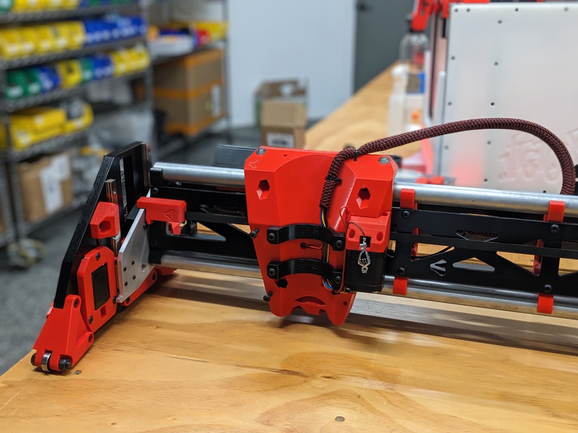
Ok, i had a bit of tike today and needed to destress a bit, so the LR3 got a bit of love
I replaced the electronic box with one of the ones from @DougJoseph stavle of designs.

Then i Frankensteined up my dust extractor together
.

So that is a whole home central vac going onto a triton dust seperator bucket
Eventuality, i will have a taller section and a boom to route out and over the table, ok that doesnt make a lot od sense, its late ans been a long day. Lol
3 Likes

Ok, fixed that opps.
Jusr a question for the smarter people that atlre playing along at home.
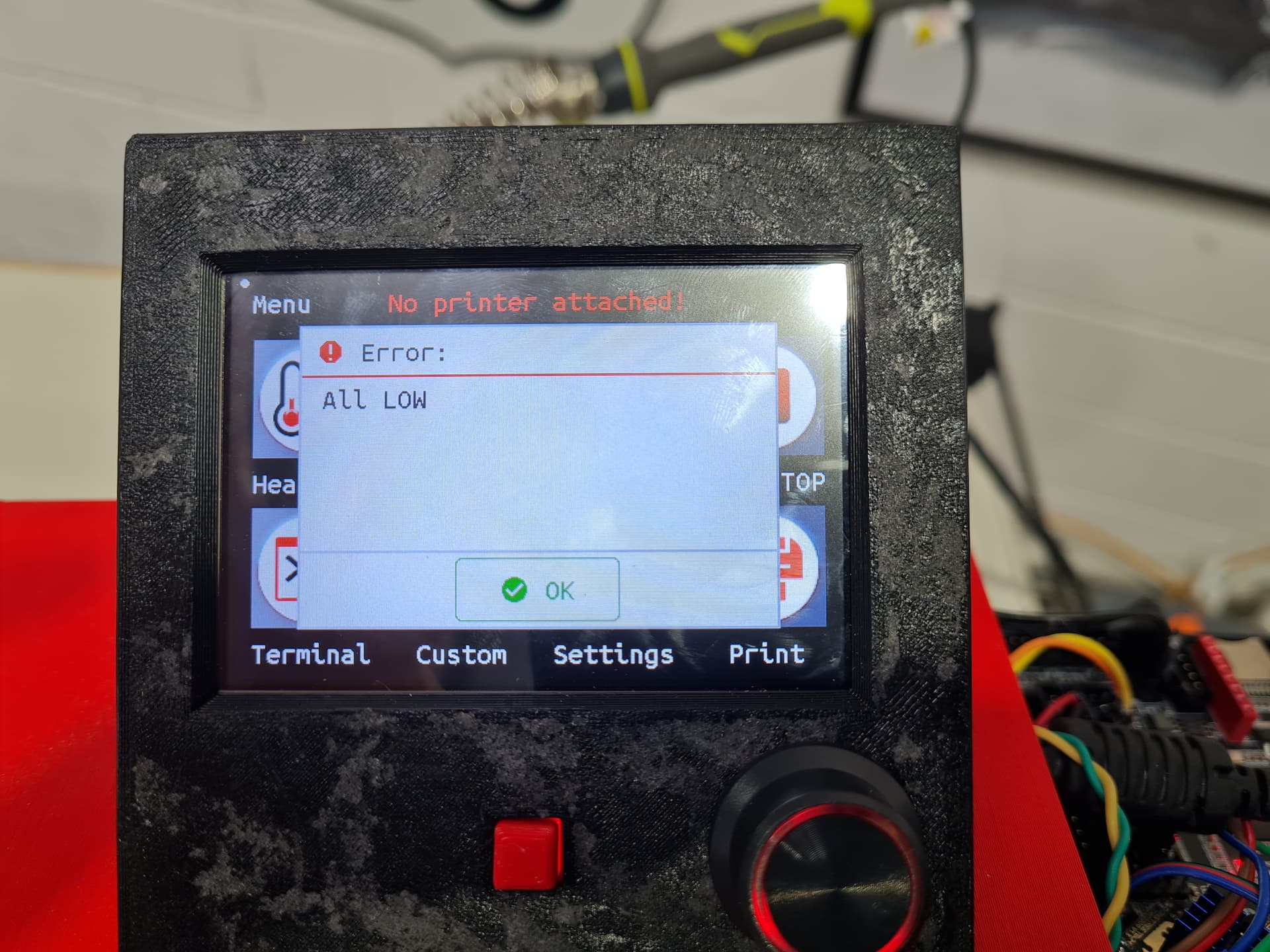
Anyidea why my LR3 says “all low”
Because it’s picking up a signal from your tyre pressure monitor?
(sorry, that’s probably not particularly helpful! ![]() )
)
2 Likes
Usually it says that when you do not have any drivers in the sockets.
Or it says that when there is no motor power.
2 Likes
Hmmm interesting.
As there are drivers in all the sockets.
Basically you plug in the power and the TFT lights up with the logo and then drops to the normal screen, but along the top there is “no printer connected” and then about 10seconds or so later there is a series of beeps and then that screen is shown. after you hit ok the LR3 is live and you can move it.
Oh and i got the spoil board in and the … “side” ones as well done this weekend (thanks @barry99705

I also checked the hight of the gantry to the spoil board after homing and it was only about 1.5mm out so a couple turns on the small screw for the endstop adjustment and its perfect.
So now I have to order the router, I am just going to go the cheapie VEVOR brand as money is a bit tight at the moment.
I also sat there for a while mentally communicating with the LR3 and we decided how I am going to do the bracing wood for the gantry. The gantry is 1475 wide between the plates, so I am going use the idea of doubling up the pipe mounts so I can cut the boards in two pieces and still mount them. After sitting there for a while I figured out that by cutting the front and bottom boards in two bits 1125 and 350mm wide I can mount them easily. And by adding a third extra pipe mount on the other end of the gantry, I could even stager the joint to limit racking/ movement due to the join at least for the front and bottom. But if I cut the one at the back in 3 pieces 1125, 250, and 100mm I can have a removable panel at the back for maybe a RPI or access to the transformer etc.
But that does leave one space between the braces at 250. (The first brace after the one bolted to the side plates) is 100mm, they have the temp braces on them, then they are spaced at 200mm. But because of the odd size, one gap is 250mm @Ryan is that ok?
(sorry for the selective pictures, its not my space so have to be careful of what is in the background…)
4 Likes
Looks good! What length is your table?
Edit: I was too fast, your gantry width is written in the topic.
That all sounds normal.
I’m sure it would be fine. I don’t remember the exact calcs I used to get that figure but I think we could easy space them out more.
1 Like
Oh i could do the math to spread them evenly, bit I thought i read somewhere that 200mm was the widest you should go…
Hi, @waimea ,
Yeah, its turned into a strange one. It was supposed to be a full 2440x1220 sheet but due to the space have I been given i decided to spin it around and mount it to a door so i could still use it.easier.
My theroy here is that if its not easy to setup and use, i will just not use it. So permanently mounted to a board is the best i can do with the space i have.
Also during my build the IDEX build was released and that has made that the width far.more usable. So that is going to happen, the parts are printing now, but i need to make cut first!!!
2 Likes
My CAD is fully parametric, I think it will work for the ~737.5 that you need.
1 Like