Another New LR3 Build in Australia

Ok, sorry i have not been updating the progress on the table.

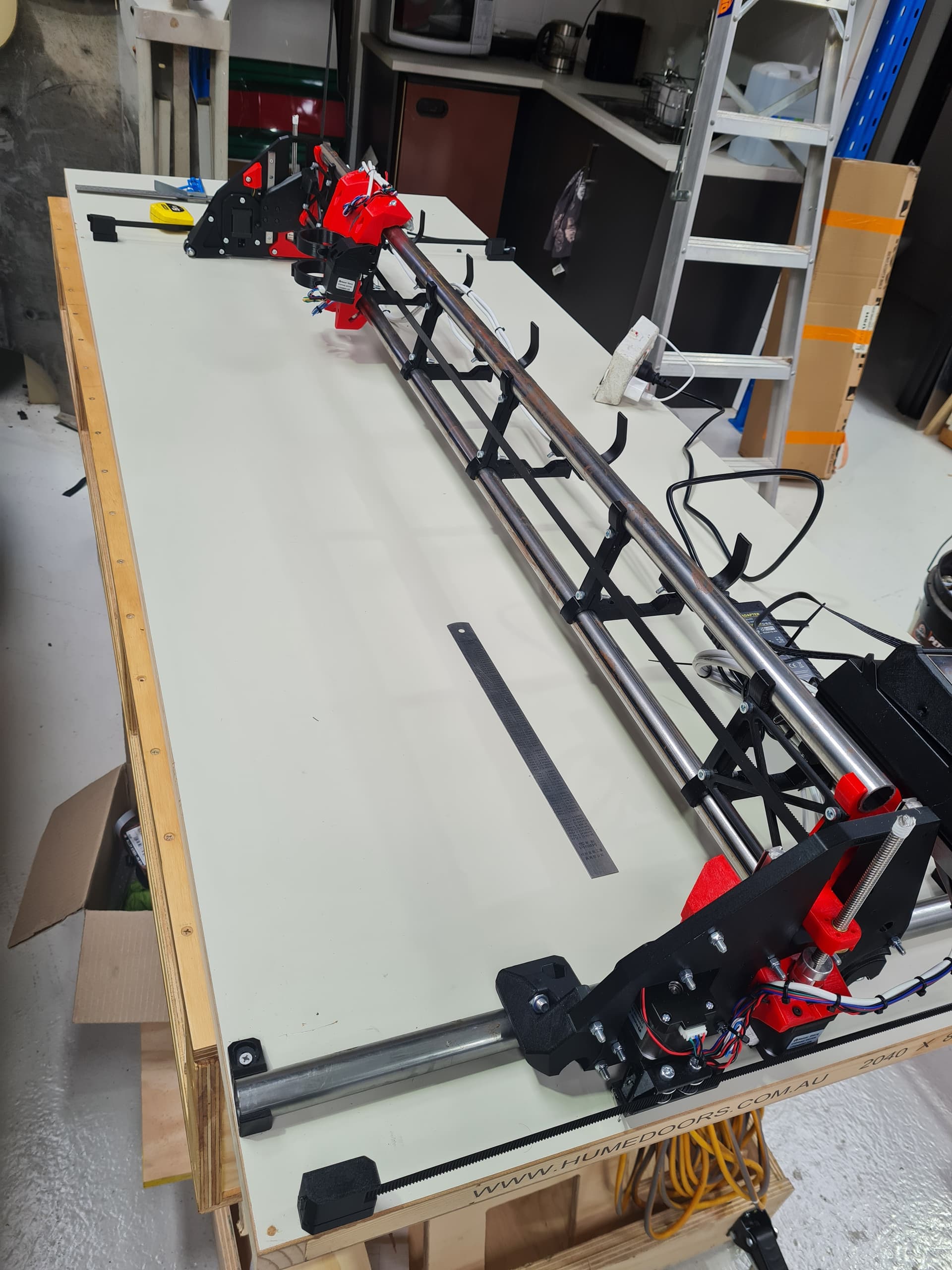
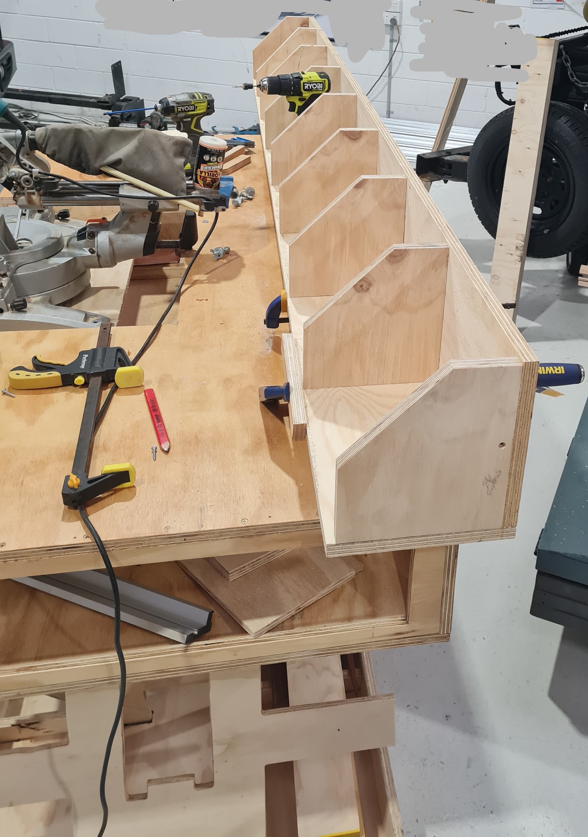
I have completed the “Wings” for the Paulk table.


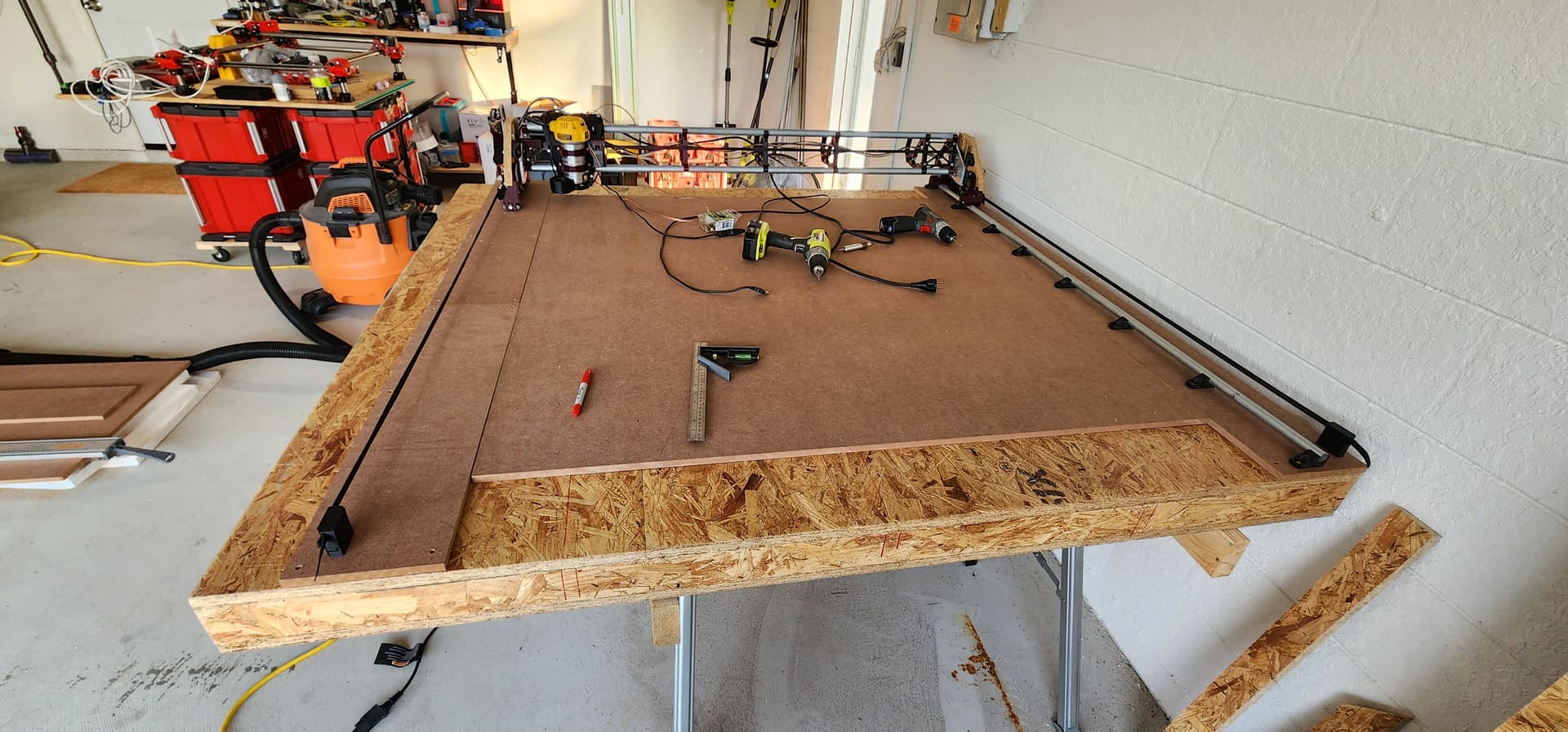
This face will be the side the LR3 will be riding on or have the rail connected to it.
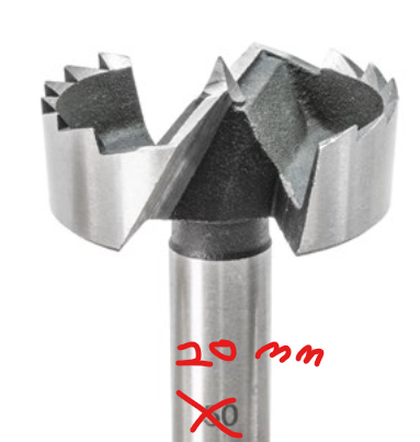
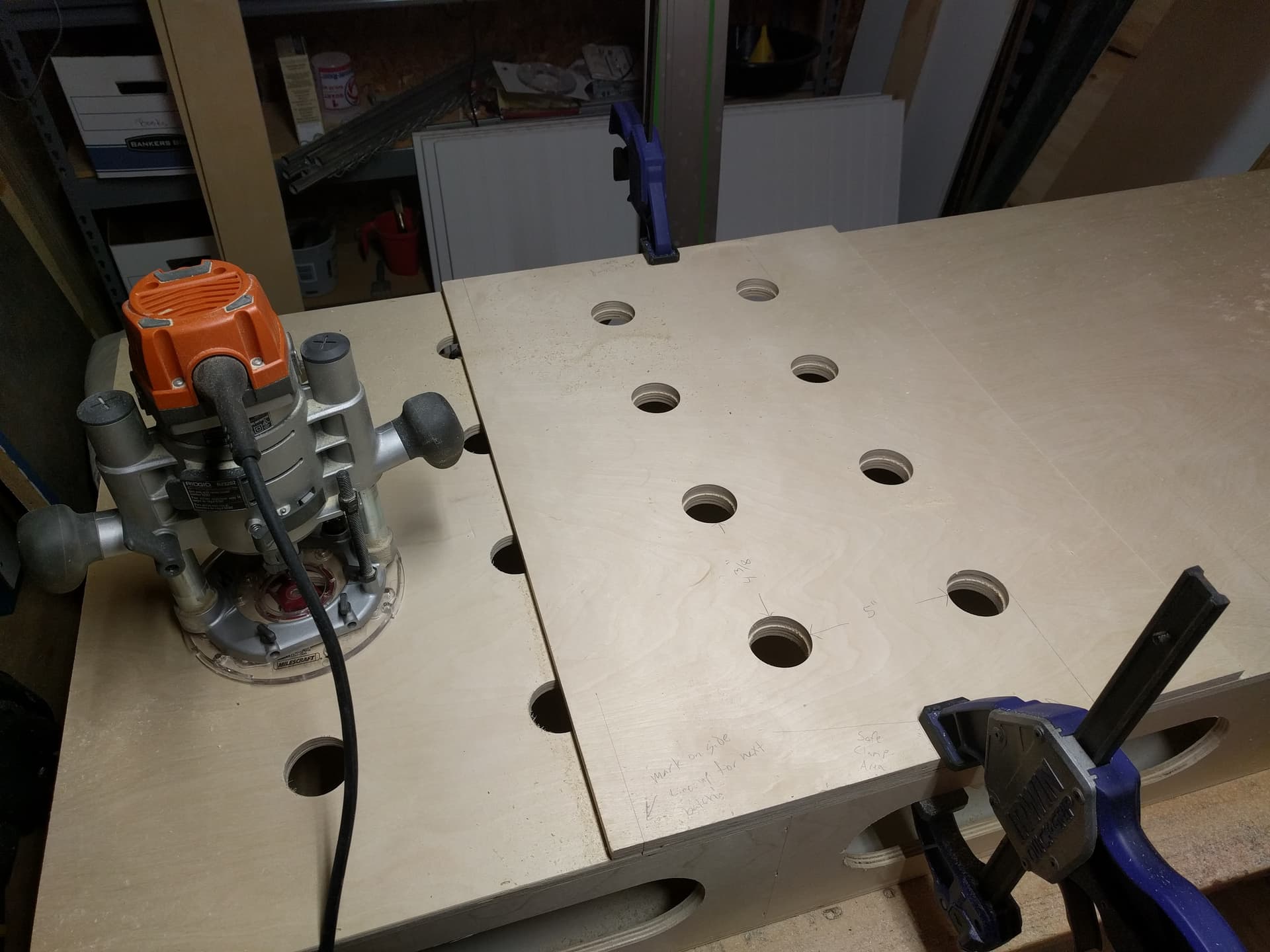
There will be another sheet of 18mm MDF on top of this to allow the connection to the bench, via the array of 20mm holes @ 96mm x 96mm centers. I am working toward the LR3 actually peck drill or maybe even cut these out. But that is a ways away just yet.
Until then i am just going to set them in place and drill a hole for a nut and bolt.

Here is another shot of the gussets.

As I mentioned in another thread I have an area in the workshop that is quite small to store my stuff, i can use the workshop, but have to pack up after myself. This area is actually under a small mezzanine and that is around 2.4m at its smallest so I was hoping to use some ropes and pullies to hoist these wings in to the air tight against the underside of the flooring to get them out of the way.
I was also considering a simple cardboard box over at least the LR3.

I also mentioned in that other thread that i was considering a smaller set of “wings” say the same length as the gantry, approx 1400mm to work on smaller projects like inlays and stuff. so that will be interesting.

2 Likes

Yep,
I got a bit of time to test the new setup and the gantry homes properly now !

Well that is all she wrote for this week, I have to drive 4 hours into the country to see my parents and do some work around the house, and then head back on sunday.

so I wont be able to take the LR3 back to the workshop and set it up on the bench. :face_with_symbols_over_mouth: :rage:
Its like having xmas and not being able to put the toy together and use it!

2 Likes

Ok, Weekly update.

Nothing. lol.

Well not exactly true, I got the LR3 back to the workshop and somehow managed to break 2 of the X supports, so I am going to have to reprint those.

I was also doing a bit of reading on the forum and figured out how to make bookmarks! I know its a simple thing, but man that is handy! Anyways via that reading I have decided to scale down my LR3. I have decided to use a standard hollow core door as the base (I have talked about this in another thread.) but due to the way I am going to have to store it, I am going to use two doors screwed together, both will have the length cut down to match my table and the cut off portion have the solid end refitted and glued back in.

I am thinking that this will give me a few advantages,
(1) Storage
My storage solution will still work with the ability to suspend it from the ceiling (hence the two doors ) it will make setup a simple matter of lowering it onto the table, probably bolt it down to some extent, then go to town.
As I spoke about in the other thread, I originally wanted to be able to cut 1220 x 2440mm sheets down, but over the break and the 4 hours drive one way to my parents place I thought about it a bit more and decided that I was not going to be doing things like that right now. Yes sure i had plans to do stuff like that, but the space i have is going to really make that hard.
(2) Ease of use
I am a big proponent of “make it easy to do and people will do it” at work. So if I need them to do something, I make is as easy as I can, I even go back to the staff after its deployed and ask “how can I make it easier/ what do you need to make it easier” after getting past the “don’t make us do it” comments, I find the best way FOR THEM TO DO IT, not the best way I think it should be done. (way more to that conversation, but I will leave it there)
If I can make it so that the only thing I have to do is lower the CNC onto my workshop table and plug it in, I am WAY more likely to use the CNC and gain the experience needed to decided what I am ACTUALLY going to be doing on it.

Down sides.
(1) not being able to cut 2440x1220 sheets down or really big parts.
again I just cant see me, right now, needing to do that.
(2) not being able to cut the 20mm grid of holes into my Paulk workbench for ultimate accuracy. To give you an idea what I am talking about
image

knowing that the holes are square, does allow you to use the bench for a lot of things from gluing to cutting.
But I think I can get around that by having the LR3 cut me some drilling templates, as big as I can and use a high quality forstner bit to do the drilling
something like this (medium quality) saw tooth unit.
image

So, more work but i think it will be better for me in teh end.

1 Like

I made a routing template for mine.

2 Likes

Now that is a great idea! thanks heaps!

I assume that you are using a top bearing patterning bit to do it?

Pattern collar on the router base.

1 Like

Ok, so i had the day off work after running around for doc appointments etc and i did a bit of work on the LR3

So i was able to get the rail mounted to the door, the belt holders and then finally the LR3 onto the door.

@vicious1 in terms of the using the door for the base of the cnc to begin with, one thing to take into account is that the screws have very little purchase into the skin of the board. In the terms of my build the rail mounts, other than to two outside ones that are screwed into the frame, are virtually only using the screw to stop them from moving, not really applying any downward pressure to the rail foot.

My only current probelm is that the X (the metal rail) is homing the wrong way. Not a big deal, but i was making all the changes to the code (remember i am using a new board) on my work PC, so even though i have my laptop i dont have the code changes.
I will fix that and move the code to my personal laptop and the make the direction change at the same time

I was a little shocked at how small the cut area is now if i am honest. But the reasoning still stands. I think that mounted onnthis door it will be easier to use and therefore i will use it.

You can reverse the direction of a stepper by reversing it’s plug. 1234 becomes 4321 and it goes the opposite direction.

Are you going to put a spoil board on it? If so, you can cut strips of board the same thickness as the spoil board, or from the same board, and glue them down to the door under the rails. This’ll give it something to screw into, and make it so you don’t lose any cutting height.

1 Like

Hi Jeff,

Thanks for that, but the gantry move in teh right direction when I press the X +/- buttons, its just the direction of homing. I seem to remember there is a section for that in the code… hopefully…

Hi Barry,

That is an excellent suggestion Barry.
I was going to do an MDF spoil board, I was thinking of two layered design which would allow a bit more space for longer bolts going into the bottom one, as the top layer would be some furniture M6 t nuts in them
image
And using the LR3 to pocket in a circle for the head of the T nut.

I will probably then deck the surface of the MDF and maybe get the LR3 to put a grid of lines on the top as I have seen done here.
All that would be so that I could replace the spoil board, as i am a bit worries of the learing curve and damaging the surface while learning. So maybe a 3mm MDF glued to the top and surface that…

Hmmmm

So gluing down the spoil board would be good as it would then be using the structure of the door (a torsion box) for flatness etc.

Ok,
God dam this marvellous / bloody horrible forum.
Damm, I am not sure if I am happy or not.

I just read the entire IDEX build thread by @jamiek, damm dude you are a mad scientist.

So now I am looking at my 1400 wide gantry and thinking…

3 Likes

No, no, no
build one and get it going, then MAYBE I will convert it.

Bwhahahahahahahahaha </crazy laugh>

ok, getting into featal position, check
start rocking, check
sucking thumb, check.

Nooooooo. Just glue down the parts the rail and opposite drive on. Like this.


My spoil board is only where it can actually cut. I’ll prolly eventually cut the two side pieces a bit narrower to make surfacing easier. Maybe.

1 Like

Yeppers, I got ya.
I was just thinking how I can do it for my setup using the door etc and also what I am thinking I want to do in the future. I especially like that you pointed out the loss of z hight if your not careful.

I have a lot of parts to cut to finished the wood work of my yacht, and I am thinking that a grid of holes to mount fixtures in, fences and clamps will be good.

Sure I can just screw them down, but hey I have a CNC.

1 Like

Hi All,

Ok, I had dome time off work over easter to do some work on the sail boat. Still lots to do on that, real fixer upper … SIGH. But I got a fair bit of fiddly woodwork modelled in CAD (Cardboard Aided Design), cut, shaped, fitted, filled sanded, painted, sanded, painted, sanded and painted. Plus some other jobs started, so now I cant procrastinate any longer over them, lol. //end boat update.

// start LR3 work. LOL
But now to give a bit of love to the LR3.

So I had a bit of an issue around the unit homing in the wrong direction. So I found that in the code under “#define Y_HOME_DIR -1” which got changed to +1 so that should fix that problem.

I also saw that @vicious1 has released a new TFT35 firmware, so I will download that and put that on as well tonight.

That should see the LR3 ready to move into Squaring and crown stage. Throw some MDF at the door as a spoil board and I should be ready to cut the braces. This might be an issue as the unit is wider than it is long… But i did see someone put them on an angle and was able to cut them, so i will measure those and figure that out as well tonight.

-=-=-=-=-=-=-=-
Now to give myself a bit more clarity around remaining jobs…
Load updated code to fix homing direction. & Test.
Try initial squaring test
Try drawing crown.
Spoil board
Measure Gantry for strut braces
Create strut braces (spiffy front one with measurements engraved.)
Cut strut braces

-=-=-=-=-
Ok, as i am using a different board the SKR EZ3 PRO, I am going to try and list the changes I am making for other people to play along at home if they want.
After Fresh ok, unzip of the SKR PRO source builds i have made the following changes:
-=-=-=-=-

BOARD_BTT_SKR_V3_0_EZ as the board in config.h
STM32H743Vx_btt as the environment in platform.io
Set “true” to invert status of all the endstops
Set “#define Y_HOME_DIR -1” to +1 (not sure if this is just my setup or not.)

now lets add this new define line In pins_BTT_SKR_V3_0_common.h, #define XMAX_PIN PC2
-=-=-=-=-=-


I cant help myself… starting to print stuff to upgrade to an IDEX build

5 Likes

Oh buddy, that is exciting. I am following along, Jamie’s has sparked an interest in me as well.

yeah Jamie has found, what I think, is the perfect middle ground.
I cant say I will get it done quickly, as i still need to get the LR3 making sawdust, dust I REALLY like the idea of it.
I will probably make a new thread on that once i get al the bits. This thread is getting a bit wild and abstract… lol.

2 Likes

Ok,
So I was at the LR3 last night (its is now at the workshop) and measured the cuttable area.
1250mm x 550mm. a bit of a far cry from what i was planning. But needs must…

Now the gantry (X or Y, I always get those confused :thinking: ) where I have to cut the panels is 1475mm, I think, or close enough & my machine will not be able to cut those in one hit.

While I was trying to make that fit on a diagonal and couldn’t I started to think about options, sure I might be able to get then cut via someone here MAYBE, but I was wondering if there is another way to do it, and my slightly broken brain came up with this “cunning plan”…

Ok I will admit I am probably over thinking this…
My “cunning plan” was to print 2 extra tube supports and glue them to another one that is about say 3/4 the way down each end of the gantry. In my slightly broken brain, this would give each panel a place to land and the two tube supports glued together would stop/ transfer any movement. Then I could cut the panels in 2 parts for each side, one larger and one smaller (think the size of a temporary strut brace or may be double the size, 2 bays instead of one), staggering the larger and smaller on each side of the gantry?

@vicious1 will this work or is there a better way to get these cut and installed? these seem important, I am assuming you are using them to stiffen the structure.