Just finishing up my second Lowrider V4 build. Everything is moving in the correct direction however the limit switches are not working, non of them.
I included the $ss and $limit test results.
Jackpot V3
Yellow brick road build
Wildcard - I do have Bart Dring's isolated RS485 card installed but have not edited the yaml file or connected a spindle to the machine as of yet.
I didn't change anything, just put in the SD card and put power to the machine
When I trigger the limit switches I do not get a light on the jackpot, The probe does work as it should however.

Thank you for the help.
I am hopeing I feel really silly once the issue is solved!

$ss
[MSG:INFO: FluidNC v3.9.9 https://github.com/bdring/FluidNC]
[MSG:INFO: Compiled with ESP32 SDK:v4.4.7-dirty]
[MSG:INFO: Local filesystem type is littlefs]
[MSG:INFO: Configuration file:config.yaml]
[MSG:INFO: Machine LowRider]
[MSG:INFO: Board Jackpot3 TMC2226]
[MSG:INFO: UART1 Tx:gpio.16 Rx:gpio.4 RTS:NO_PIN Baud:115200]
[MSG:INFO: I2SO BCK:gpio.22 WS:gpio.17 DATA:gpio.21Min Pulse:2us]
[MSG:INFO: SPI SCK:gpio.18 MOSI:gpio.23 MISO:gpio.19]
[MSG:INFO: SD Card cs_pin:gpio.5 detect:NO_PIN freq:20000000]
[MSG:INFO: Stepping:I2S_STATIC Pulse:2us Dsbl Delay:0us Dir Delay:1us Idle Delay:255ms]
[MSG:INFO: User Digital Output: 0 on Pin:gpio.26]
[MSG:INFO: User Digital Output: 1 on Pin:gpio.27]
[MSG:INFO: User Digital Output: 2 on Pin:gpio.0]
[MSG:INFO: User Digital Output: 3 on Pin:gpio.2]
[MSG:INFO: Axis count 3]

[MSG:INFO: Axis X (3.000,1223.000)]
[MSG:INFO:   Motor0]
[MSG:INFO:     tmc_2209 UART1 Addr:0 CS:NO_PIN Step:I2SO.2 Dir:I2SO.1 Disable:I2SO.0 R:0.110]
[MSG:INFO:  Neg Limit gpio.25]
[MSG:INFO: Axis Y (3.000,2443.000)]
[MSG:INFO:   Motor0]
[MSG:INFO:     tmc_2209 UART1 Addr:1 CS:NO_PIN Step:I2SO.5 Dir:I2SO.4 Disable:I2SO.7 R:0.110]
[MSG:INFO:  Neg Limit gpio.33]
[MSG:INFO:   Motor1]
[MSG:INFO:     tmc_2209 UART1 Addr:3 CS:I2SO.14 Step:I2SO.13 Dir:I2SO.12 Disable:I2SO.15 R:0.110]
[MSG:INFO:  Neg Limit gpio.35]
[MSG:INFO: Axis Z (-147.000,3.000)]
[MSG:INFO:   Motor0]
[MSG:INFO:     tmc_2209 UART1 Addr:2 CS:NO_PIN Step:I2SO.10 Dir:I2SO.9 Disable:I2SO.8 R:0.110]
[MSG:INFO:  Pos Limit gpio.32]
[MSG:INFO:   Motor1]
[MSG:INFO:     tmc_2209 UART1 Addr:3 CS:I2SO.19 Step:I2SO.18 Dir:I2SO.17 Disable:I2SO.16 R:0.110]
[MSG:INFO:  Pos Limit gpio.34]
[MSG:INFO: X Axis driver test passed]
[MSG:INFO: Y Axis driver test passed]
[MSG:INFO: Y2 Axis driver test passed]
[MSG:INFO: Z Axis driver test passed]
[MSG:INFO: Z2 Axis driver test passed]
[MSG:INFO: Kinematic system: Cartesian]
[MSG:INFO: STA SSID is not set]
[MSG:INFO: AP SSID FluidNC IP 192.168.0.1 mask 255.255.255.0 channel 1]
[MSG:INFO: AP started]
[MSG:INFO: WiFi on]
[MSG:INFO: Captive Portal Started]
[MSG:INFO: HTTP started on port 80]
[MSG:INFO: Telnet started on port 23]
[MSG:INFO: Probe gpio.36:low]
ok

$Limit
Thank you MakerJim for the advise. I ran the command and captured the results.
I see others post a nice neat report, sorry this is the best I could do.
Clicked Y 1
<Idle|MPos:0.000,0.000,0.000|FS:0,0|Pn:Y>
:                     Y
:                     Y

Clicked Z1
<Idle|MPos:0.000,0.000,0.000|FS:0,0|Ov:100,100,100>
:         Z
:         Z
:         Z
<Idle|MPos:0.000,0.000,0.000|FS:0,0|Pn:Z>
:         Z
:         Z

Clicked X
<Idle|MPos:0.000,0.000,0.000|FS:0,0|Ov:100,100,100>
:
:              x
:              x
:              x
<Idle|MPos:0.000,0.000,0.000|FS:0,0|Pn:X>
:              x
:              x
:              x

Clicked Y0
<Idle|MPos:0.000,0.000,0.000|FS:0,0|Pn:Y>
:               y
:               y
:               y

Clicked Z0
<Idle|MPos:0.000,0.000,0.000|FS:0,0>
:   z
:   z
:   z
:   z
<Idle|MPos:0.000,0.000,0.000|FS:0,0|Pn:Z>
:   z

Clicked X
<Idle|MPos:0.000,0.000,0.000|FS:0,0|Ov:100,100,100>
:
:
:
:              x
<Idle|MPos:0.000,0.000,0.000|FS:0,0|Pn:X>
:              x
:              x
To be frank no I am not. I had help at this point and well, you know. I am sure this has to be the issue however X also failed to recognize the limit stop.
I will try to sort this out this evening.
Thank you for the help.
Question, I have a jackpot v1, when the limits are triggered it lights up an led on the board. The plan was to use this function to identify each limit switch to make sure they were in the correct position, however I am not getting any lights on the jackpot v3. Is this the expected behavior for this board?
Yes it is. Ryan decided against leds on the JP3 to save space and cost. We now us $Limits to see what is being triggered. I would double check to see where each limit switch is plugged in. They could all be shifted over so they don’t work when homing.
I am sure this has to be what is causing my problem. I should be able to get back to this tomorrow. I will trace everything out and make sure everything is where it should be.
Thank you Jim, the light at the end of the tunnel is getting brighter by the day. I have enjoyed the building and learning almost as much as I enjoy the items this thing allows me to make.
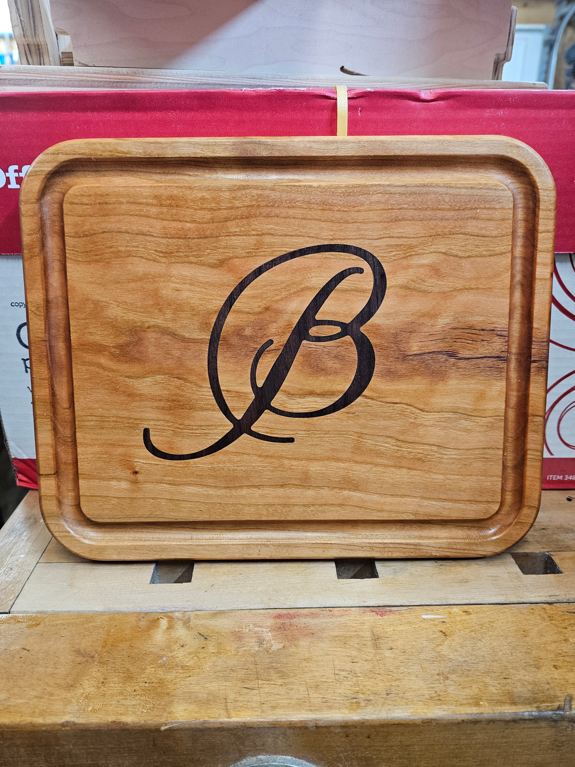
Okay, then I applaud you, because it looks really, really great!
You cut it with a straight endmill I supposed since MillMage does not support V-carve inlays yet, correct?
Dang Bob, from having issues straight to a fantastic inlay. Congratulations.
And, don’t worry about it, we all make simple mistakes. The lowrider v2 almost didn’t exist because it took me three days to find a loose grub screw on a pulley.
It was made with a flat bottom 1/8 inch endmill. The female pocket is .002 inches larger than the male insert. I do the male part first then the pocket at a very tight tolerance. I then enlarge the pocket at a rate of .001 inch until I can get the male part to fit. I did have to modify the font in a few places so the mill would fit without enlarging the font.
Ryan:
This is my second Lowrider V4 build. The first one is a 24 x 48 size, this is the machine the cutting boards were made on. I have a need for a larger format machine, my wife and I talked about it, niether could stomach the thought of dismantling Clyde because he just always does the job.
I have heard that the smaller machines are more ridged, I hope the new larger machine can match the work Clyde has been able to produce. The new machine is 50 x 60 for now with it being extended to a final size of 50 x 100 once the new shop is completed. I have lots of cabinets and signs to make creating the need for a larger format machine.
Thank you everyone for the help and the kind words.