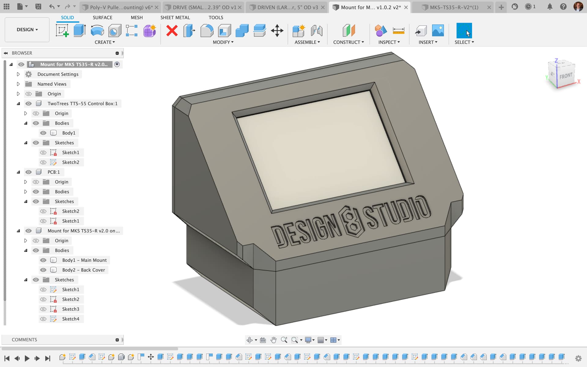
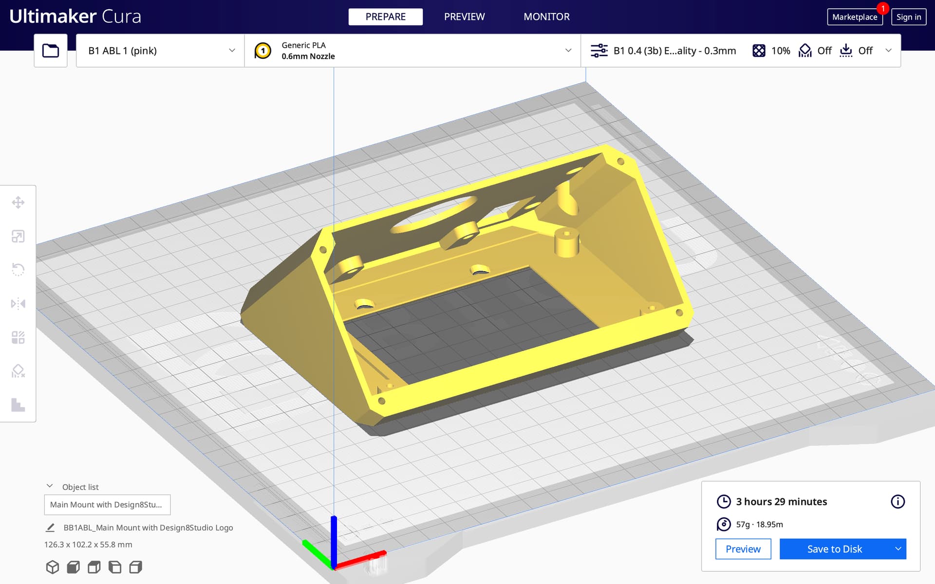
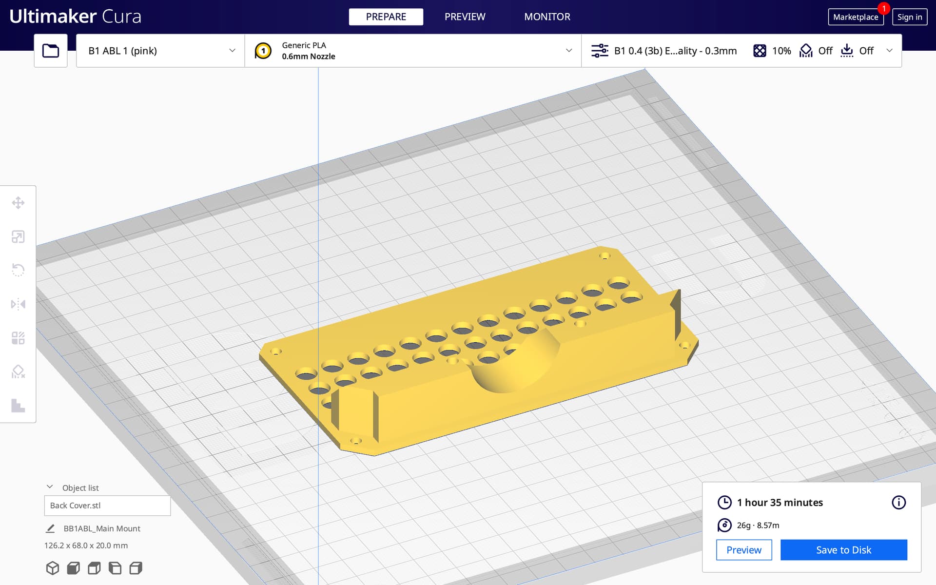
However, I also worked to add an MKS touchscreen (model TS35-R v2.0) to the same TwoTrees TTS-55 diode laser rig. I got it installed, including designing a 3D-printed holder that mounts both the existing metal control board box (at the bottom) and the new touchscreen, onto the aluminum extrusion at the front of the rig:
The wiring is right, and the stock firmware of the touchscreen “works” (right out of the box!) in a “laser mode” that controls the GRBL based rig. The touchscreen and mainboard are both MKS items.
Major issues (2) & minor issues (2)
1. The laser rig has “lost” USB control via Lightburn on laptop. Without the touchscreen, laptop control worked. With it, laptop control does not work. Any ideas?
2. Framing of job and cutting of job are in wildly different locations!!! Framing location seems correct. Actual cutting is way off in wrong location. This is cutting from a GCode file outputted by Lightburn, and transferred to SD card which is placed in TTS-55 main board, and run from there via the MKS touchscreen. Any thoughts?
3. The stock firmware on MKS touchscreen “works” with the MKS control board, but it is in portrait mode instead of landscape mode, and my need is for landscape, so user interface is sideways. “Settings” page has no option to switch orientation. Anyone have MKS touchscreen firmware that is compatible with laser burning and that is in landscape mode?
4. The stock firmware on MKS touchscreen “works” with the MKS control board, but it is a “black and white” theme, whereas I have seen nice colorful themes. (Plus it is in portrait mode instead of landscape mode.) Anyone have firmware compatible with laser burning that colorful (and is in landscape mode)?
The TS range of screens from MKS are specifically designed for their DLC32 main board. You say the TwoTrees laser machine has a MKS mainboard fitted but can you confirm the model number of it?
The TS range of displays is, AFAIK, just a dumb screen with all the programming done by the system board electronics, if the twotrees has a different system board the fact that it works at all is a miracle!
The TS display does indeed have a colour display when used with the DLC32 system board.
It sounds like the screen is ‘taking over’ the serial port of the system board when it is connected, are you sure the USB does not work at all?. This might indicate the twotrees system board has only one serial port defined in its firmware.
It sounds like you have two different origin locations between lightburn and the touchscreen…not sure on that one!
Landscape mode is the default when driven from a DLC32 and the firmware for the system board comes pre-compiled so there is no way to see if there is a ‘rotate screen’ option. There is also a config.txt but there is no options in there for the screen orientation either.
Perhaps your best solution might be to get a DLC32 board (assuming the twotrees board isn’t one already!) €16.24 shipped!
The TwoTrees board is listed as “Makerbase MKS LTS v1.1” and it’s apparently very similar to (apparently a slightly cheaper to make version of) the Makerbase DLC32.
That got me essentially the same portrait mode, mostly B&W interface I had before, but I must have some GRBL PWM / frequency settings wrong, because laser power is dimenished.
So then I tried the former. I installed the v2.2 firmware (that’s made for DLC32 board_v1.0), and it gets me the landscape mode with nicer, more colorful interface. However, the laser won’t come on, neither when connecting LightBurn on the laptop, or when running GCode from the SD card. — And again, that may related to me having some GRBL PWM / frequency settings wrong.
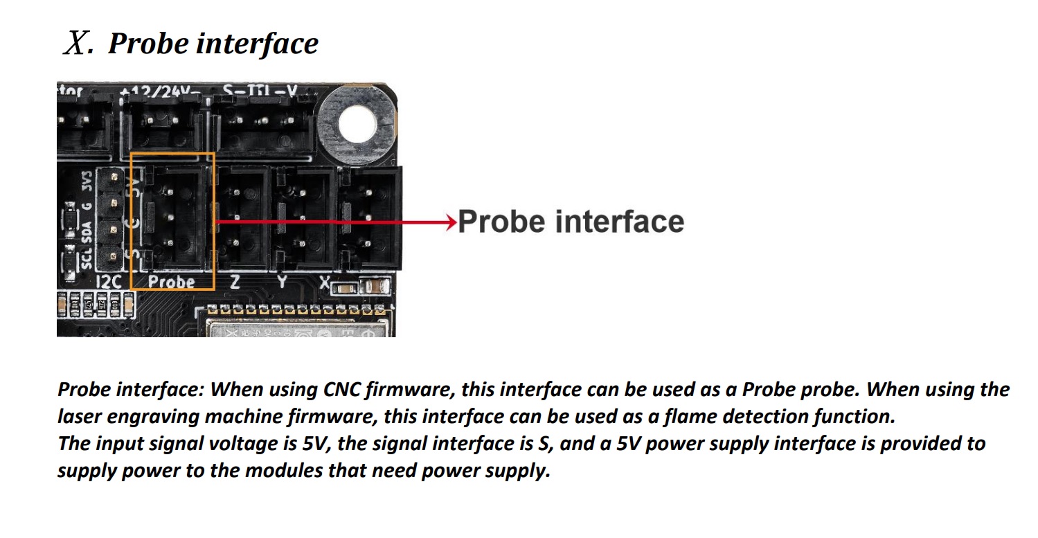
An added bonus to having the DLC32 is it can be fitted with a flame detector which is a useful appliance for a laser machine!! It works really quite well.
After doing some various flashing and reflashing, I did see that I could get USB and touchscreen at the same time, if I was careful on the USB port being right and not confused.
It may have been a difference between “absolute” coordinates and “user origin” coordinates. I still have some strange strange differences between job “placement” from the SD card when compared to USB…
Update: I’m about to order that board. I’m assuming I need the one that comes with what looks like 3 little “stepper driver” type boards. It is listed as costing $15.12 (USD) before tax, and with free shipping.
You appear to be missing the $32 laser mode in your command list. Maybe that has something to do with your laser not working!. It will certainly affect the quality of engraving you will get because laser mode enables M4 operations.
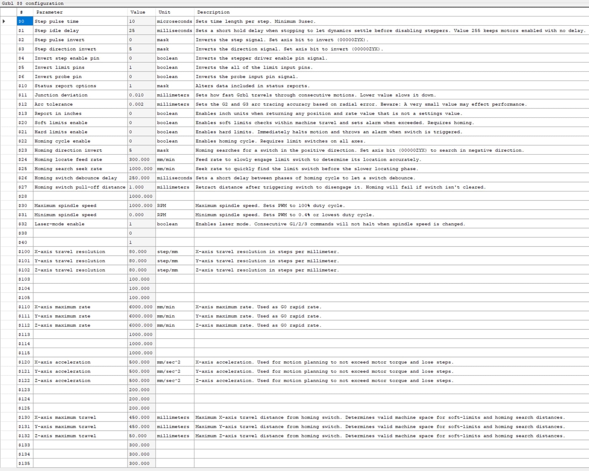
Here is a screenshot of my DLC32 GRBL config (not actually set up for a machine as it is just a spare board for me)
with $28 and $32 being the most obvious differences.
You could continue to mess around with user modified firmwares… or just buy a DLC32 and go with the official firmwares!
I see you have made a decision!
That board will need three stepstick type driver modules, I assumed your existing dlc board used the same, if not you will need to add the three driver modules, either A4988,drv8825, tmc2208, tmc2209 standalone. Any will do. I use TMC2208 because they are very quiet in operation.
I will double check. There seems to be a significant difference between what gets exported from LaserGRBL, versus what gets exported from Lightburn. Here’s the “more complete” list that came from a LB export.
CORRECTION: the difference was perhaps between a “suggested” set of values I downloaded, versus what came from … LaserGRBL? Makerbase utility? I am now confused as to what I first posted above, and what’s below!
UPDATE: The values below are not from LaserGRBL, they are from a Makerbase flashing and configuring utility:
Also, regarding $28: I tried to write that to the board, but I seemed unable to get it to “take”… yet it shows above as being written. I had no idea what value to write, so I had tried a “10” !!
OK…but that is using lightburn. Lightburn may be adding that parameter because it isn’t in your LaserGRBL config and it is in my laserGRBL config from every single GRBL board I possess. This will surely degrade your results when using LaserGRBL will it not?
If you are getting a DLC32 all this is mute. Presently your LTS board is using a user-inspired firmware and who knows what is going on. I can confirm the DLC32 laser firmware is in colour when connected to a TS35 display, is in landscape mode and does work a laser connected to the TTL socket.
It would be interesting to hear your comments after all this is sorted out and you have tried both Lightburn and LaserGRBL about each programs functionality. I know lightburn is well regarded and I think LaserGRBL does a fantastic job too and doesn’t get the kudos it deserves as a free software that manipulates bitmap files into excellent engravings.
You will only need two stepstick drivers as you don’t need the Z axis…
Thank you so much. The updated post (above) reflects that the outputted GRBL values are taken from the board by an MKS utility and exported as an .NC file.
I may try one or two other previous firmware versions before pulling the trigger on the other MKS board… see if I can get something functional.
UPDATE
OK, so I backed the firmware version down to 2.0.8_H35, dated Jan 5, 2022, and it gets me a working laser, and a landscape mode with a colorful interface. I may not have to order the replacement board after all!
Laser works again, but in LightBurn it still does not work unless I switch on “Constant Power Mode“ and I still think it is weaker than it should be. I may order that other board after all.
Seeing as how your LTE board is supposed to be a low cost version of the current DLC32 (by virtue of it only having two channels) perhaps you might like to try the current dlc32 firmware on your board?.. What could possibly go wrong?
It may be the same firmware because the DLC32/TS35/laser firmware also has a V2.0.8_H35_20220105_N.bin
One last thought before pulling trigger on the other board…
Is there any chance the laser’s weakened output is due to a lack of power? The power supply brick that came with the laser was 4 amps (12v). Is it possible the 4 amps is enough, but barely enough, and adding the screen tips it over to not being enough power?
OK, I just switched out the 4 amp 12v power supply for a 6 amp 12v power supply, and it seemed to make no difference. Maybe I’m just imagining that it’s falling short of full power. I guess I need to locate a repeatable test on a trustworthy “repeatable” type of material (with already known results) and see if I can replicate it.