I got a great deal on a purchase of a used TwoTrees brand laser engraver, model TTS-55, which is a 5.5W diode. It’s a nice entry level laser CNC rig. It has a vertical screw for adjusting focal distance, and a horizontal screw for locking in the height, once set.
I bought it from their website, under their clearance page, which has some used items, which they certify as fully functional. Mine was like new, everything was included, and I cannot see any way in which it was not like buying a new unit, except I agreed in advance to not have access to after-sales support.
I also bought the extension kit for it, so its usable area is enlarged by a considerable amount, and I also bought their air assist kit, which is nice, with a knob for adjusting how much air it puts out. It claims to be capable of 30L/min. I don’t know that I have a way to test that, but at the full setting, the air flow at the laser “nozzle” is good and strong.
The laser rig comes stock with a nice metal “focal length assist column” and comes with a 3D-printed holder for it. However, the printed holder’s cup was too small to hold the column. So, I designed an improved version of the holder, available here:
Here’s a quick video I made about the new holder, which can also work for the same column on at least three different models of laser rigs from TwoTrees:
, TTS-55 (5.5W), TTS-10")
Mod’ing to add end stops for homing
One of the niceties that this entry level rig lacks is end stops for homing. There are at least a couple of nice videos about adding those, but they seem based on using a more “complex” end stop switch (a Makerbase design) that has circuitry on it, while the end stop switches I already had on hand are the more “simple” ones, like those we use on V1E LowRider v3, and such.
End Stop install & related details
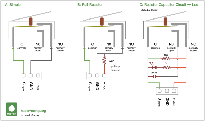
I chose to use the common, “simple” end stop switches that don’t have such things as pull-up resisters or circuitry, and to use wiring for the “Normally Closed” circuit method instead of the “Normally Open” option. My understanding was that the GRBL based control board comes set to expect “Normally Open” switches by default, and I would need to edit the GRBL Settings parameter identified as the “$5” value to switch for “Normally Closed.” (I cannot remember right at this moment if it was already right or had to be changed.)
Wiring was done as shown in “A: Simple” scheme on this web page:
… Again, the wiring plan I used is the “A: Simple” option in this illustration:
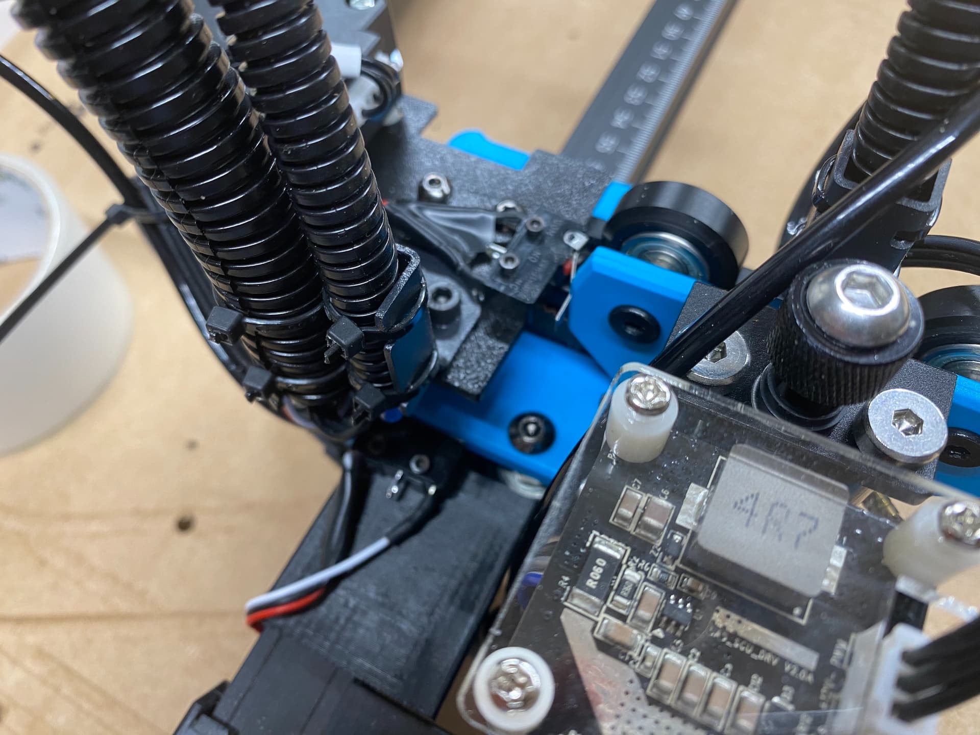
On the motherboard / control board inside the laser, which (on my edition) is a “Makerbase MKS LTS v1.1” there are four pin-set ports in the upper right: one for a “probe,” and three for end stops: Z, Y, and X. The ports have three pins each, and the pins are labeled (from top to bottom) as 5V, G, and S, which stands for 5 volts, Ground, and Signal.
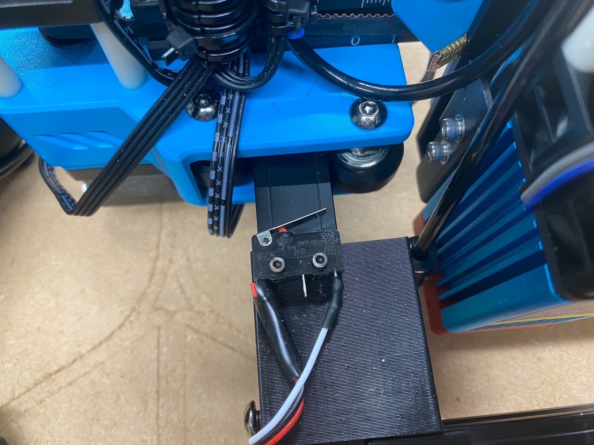
As shown above, the “COM” (or Common) tab on the end stop got soldered to a wire that connects to the “S” (signal) pin, while the “NC” (Normally Closed) tab on the end stop got soldered to a wire that connects to the “G” (or Ground) pin. This works for me.
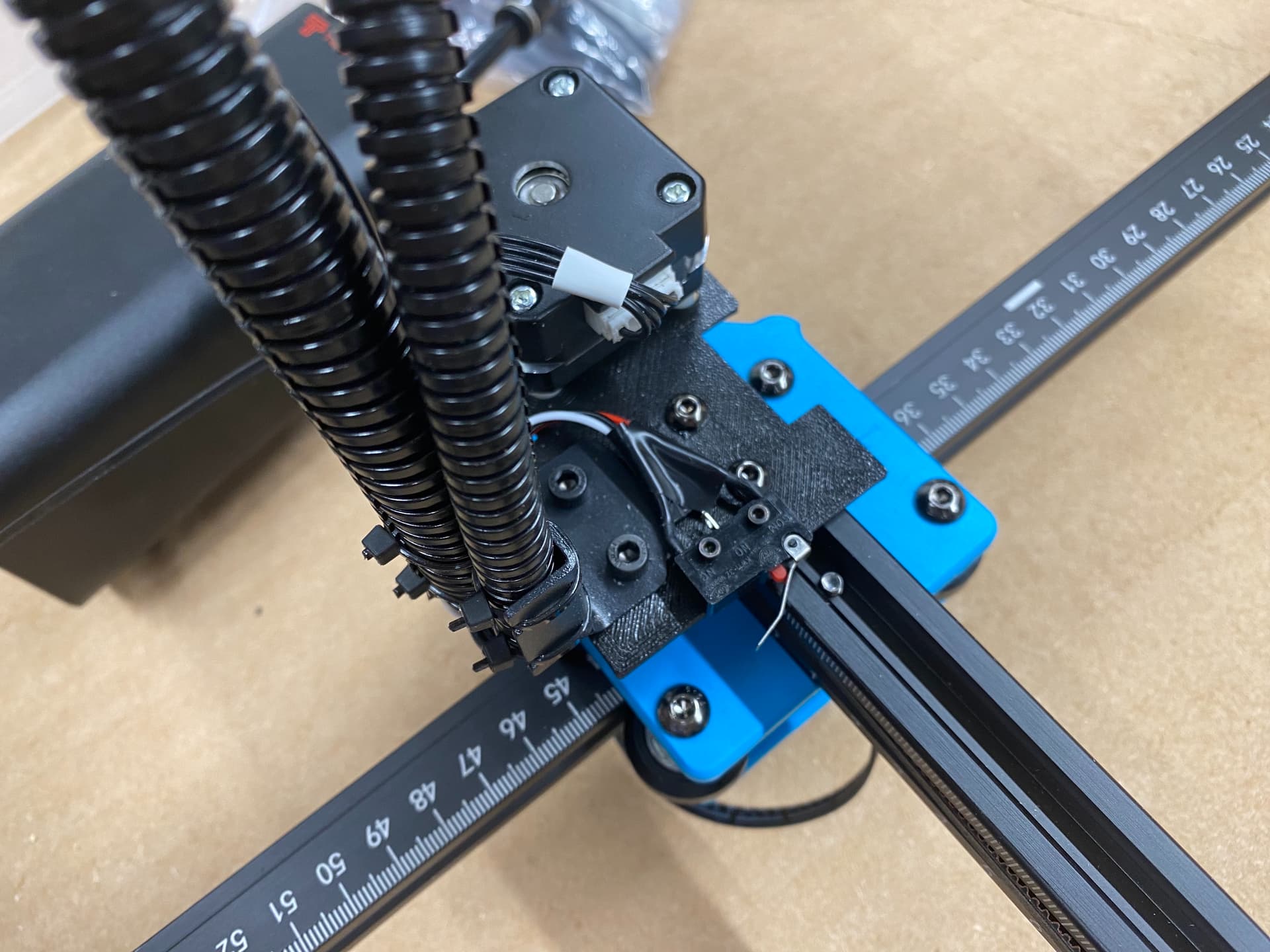
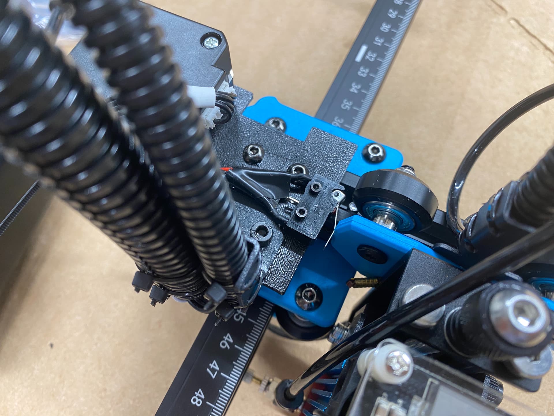
Below are some pics of the main board, with the first end stop switch installed for “Y” — and some pics of the Y end stop itself, which is attached to a printed mount I got from a thingiverse listing here, followed by some pics of the X end stop, also attached to a printed mount from the same listing. Be aware that one of the two mounts in the listing was not correctly oriented for printing. I had to rotate the part in the slicer to lay it flat for printing.
The thingiverse listing for the mounts is related to this video about installing end stops:

I eventually found out that not only can the GRBL Settings be edited and written out to the control board using LaserGRBL software for Windows, but also by LightBurn, which is available for Mac or Windows.
In order to use the USB connection to the device, controlling it by my laptop, I had to install a port driver.
I installed the port driver for Windows that came with the device (on a memory card that came with provided software, drivers, test files, etc). An adapter was provided so the memory card can be used on computers.
I also later searched the web and discovered a port driver for Mac, and I downloaded and installed it too, so I can control the device with LightBurn on the Mac side as well as on the Windows side.
The port driver for Mac, mentioned above, was obtained from here:
…but is also apparently available from here too:
Other tweaks
In order to get this thing working like I wanted it to, I had not only tweaked the “Y homing direction invert” option inside the GRBL Settings, but I also tweaked some Device Settings inside LightBurn as well.
One of the helpful Device Settings was to enable the “new” $J jogging option, which causes any jogging (that occurs after homing) to respect the boundaries of the work origin, by simply stopping the laser head if you try to move out of the bounds of your set usable area.
Another couple of settings I adjusted were to set the “user origin” as the center of the actual work area, and to tell the LightBurn app that I want to use “user origin” for jobs, and (in Device Settings) that, after a laser job completes, I wanted the device moved to those same “centered” coordinates , instead of back to the homed universal 0,0 that was found during homing.
If you are trying this modification, please let me know if you have any problems or questions.
Makerbase MKS LTS v1.1 board with Y end stop wire connected 01

Makerbase MKS LTS v1.1 board with Y end stop wire connected 02

Makerbase MKS LTS v1.1 board with Y end stop wire connected 03

TwoTrees TTS-55 (5.5w) Laser Engraver w Y end stop added on 3D-printed mount 01
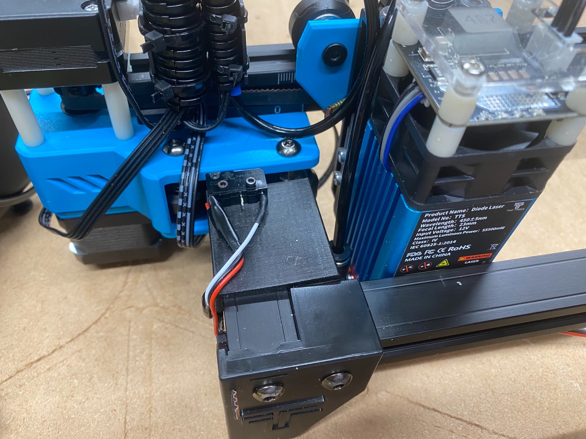
TwoTrees TTS-55 (5.5w) Laser Engraver w Y end stop added on 3D-printed mount 02
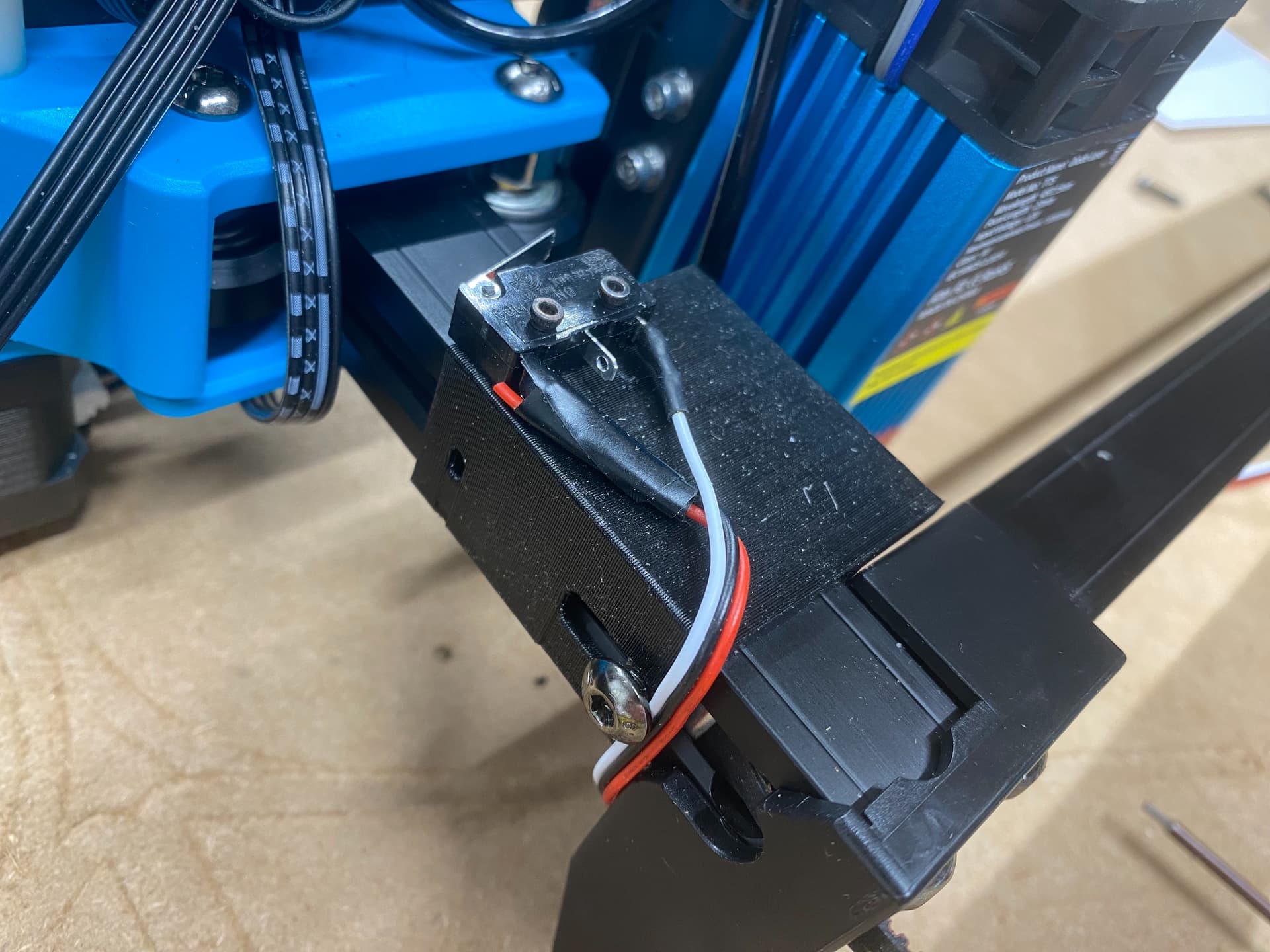
TwoTrees TTS-55 (5.5w) Laser Engraver w Y end stop added on 3D-printed mount 03
TwoTrees TTS-55 (5.5w) Laser Engraver w X end stop added on 3D-printed mount 01
TwoTrees TTS-55 (5.5w) Laser Engraver w X end stop added on 3D-printed mount 02
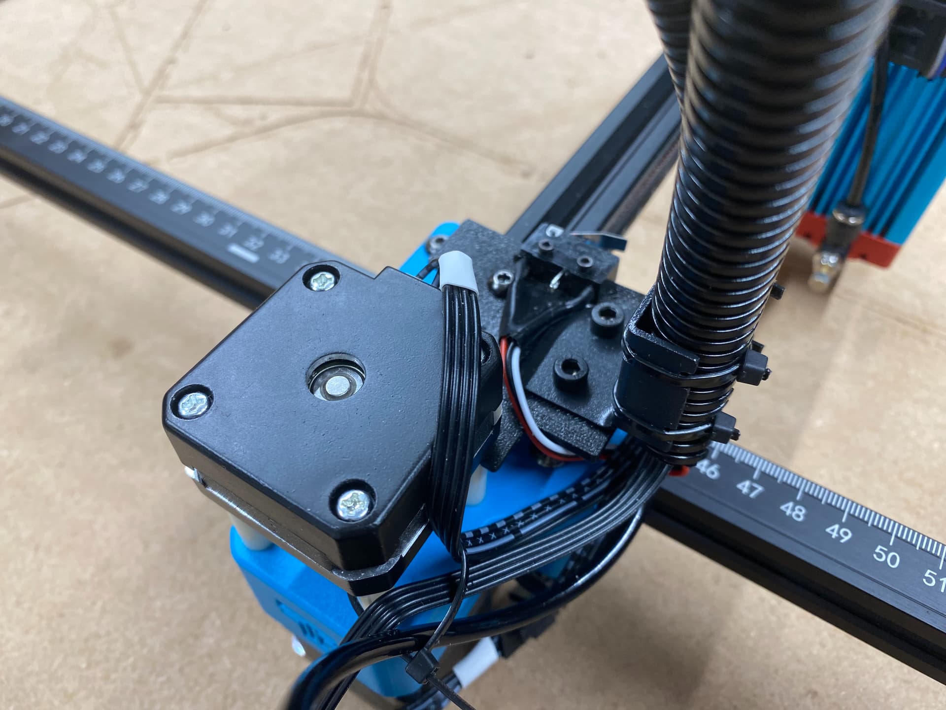
TwoTrees TTS-55 (5.5w) Laser Engraver w X end stop added on 3D-printed mount 03
TwoTrees TTS-55 (5.5w) Laser Engraver w both X and Y end stops added on 3D-printed mounts 01