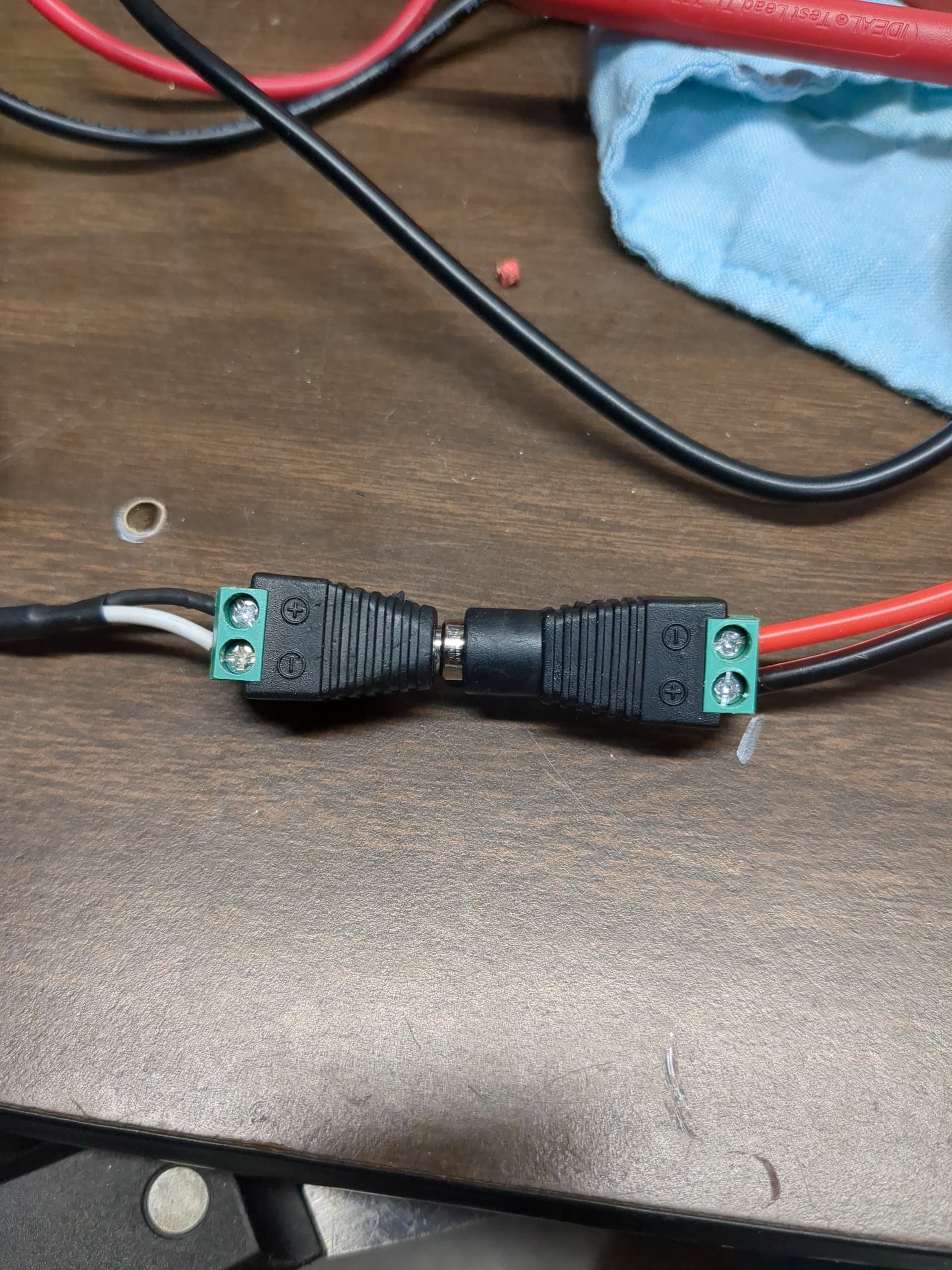
Got the 24v PSU from the V1E store. I terminated black to + and white to - on the male power connector, and I terminated black to + and red to - on the spade cables that came with the SKR (also V1 store).
When I test continuity from the spade terminals to the prongs in the power supply, I get continuity on the center pin of the power supply and wall plug for both spade terminals. Is this how it’s meant to be? I thought the center pin was meant to be ground, one vertical prong is +, and one is -.
This is for the 24V output from the power supply? The power into the power supply of 110 would not be using one of these plugs.
Typically the center is + and the outer is - for all the ones I’ve used. Maybe follow the labels next to the screw terminals. Red is +, black is - typically for DC, while white is neutral - , black is + for AC home wiring. You aren’t showing where the wires come from or attach to…
It really doesn’t matter what the +/- are on the plugs as long as white goes to red then and black to black.
Is the output voltage truly 0 V? If you disconnect the power supply from the barrel plug, can you get a reading on the output? I bought a few of those plugs from microcenter and the little bolts stripped right out and didn’t hold anything.
I haven’t tested output voltage yet - I’m just out to make sure that when I plug it in, I don’t fry the board.
The white and black wires are from the power brick. The red and black wires are the spade connectors. I removed the terminated barrel plug and tested directly on either the white or black wire - both show continuity to the center prong on the power brick itself.
Should I be using the DCV setting on my multimeter to test output voltage?
I’m not quite sure what your concern is, but as long as both terminals (+ and -) do not have continuity with each other, then everything is fine.
Although I would suggest you change your cable colors. Red is usually + or VCC in DC applications, and - or GND is usually black. As for white and black, those are more commonly found for AC applications. White is the neutral line, and black or gray is the phase.
If I have to use other cable colors besides red and black in DC, I use all light colors (red, white, yellow) for + and all dark colors (black, blue, brown) for -. If you do something like this, I would suggest you stay consistent with your color coding because it will confuse you at some point.
Back to the problem. You should check with your multimeter between your terminals. If the barrel connector is connected and you measure with the multimeter between + and -, and there is no continuity, everything is fine. Before connecting, just check which cable is which to connect it properly to your board.
Edit - I’m an idiot - I missed that you are using Black and White wiring on the DC side of the PS. Ignore the message below, which assumed that you were talking about the Black and White AC wires on the PS.
I’m leaning on my electrical theory courses from a few decades back here, but I think this is normal.
Normal (North American) wiring standards are:
White - AC Neutral
Black - AC Line
Green - AC Ground
Red - DC +
Black - DC -
The AC side of the PS is basically a transformer coil, which is just a long piece of thin wire wrapped around something. The DC resistance will be quite low (< 1 Ohm) between the two ends of the wire. AC impedance will be higher due to reactance, so it doesn’t blow the circuit breaker when you plug it in.
The Neutral (white) is connected directly to Ground (green), so resistance will measure almost 0 Ohms. The Line (black) is connected indirectly to Ground through the coil winding, so resistance between L-G should measure very marginally higher that N-G (maybe as low as a few tenths of an Ohm), but pretty much the same as L-N.
The DC side is different in that, in addition to the low side transformer coil, it will have some type of rectifier (diode bridge is most common) and possibly a voltage regulator (Zener diode or other method) to limit/adjust the DC output to the specified voltage. Depending on the design, measuring between + (red) and - (black) may have high resistance in one direction and low resistance in the other.
As mentioned, it’s been a few decades since I did any electrical theory, so I may be out to lunch here, but IMO a better test of the transformer (PS) is to simply plug it in and measure output voltage,. Just visually check your AC cord to make sure that you have connected everything properly at the plug end and at the PS terminals
This seems wrong. Red is normally +, Black is normally -. It’s not standard to use Black and White for DC, but that is what you have. As mentioned above by @Jonathjon , the White wire is + and the Black wire is -. Connect that white wire to the same jack terminal as the red wire and connect the red wire to the + on the SKR.
You could also toss the power connector, crimp some spade connectors to the PS wires, and directly connect Black to SKR - and White to SKR +. This will be much more secure, and will prevent accidental disconnection during operation
Is it very short or is it continous ? Most of the times when you have a very short moment of continuity between vcc and gnd, because there is most probably a capacitor that is charged by the multimeter. If you have true continuity e.g. when the multimeter ist just beeping the whole time, then you may have a bad PSU.
Did you test the psu without the wires to meake sure that definitely nothing in between the PSU and the connector ?
@Bartman
I’ll be using this box, which has a cutout for the female barrel plug adapter. It won’t come out during operation.
When you say plug in the power supply, you mean to a regular household outlet with the multimeter connected to the bare black and white wires on the DC side? I’m a bit hesitant to connect this to live electrical current if it’s going to blow out my multimeter or the power supply.
@Fabian
It’s continuous for a moment before fading out. My multimeter doesn’t beep, but the display does show only a short continuity moment that seems to persist until I switch the multimeter leads. Quick video showing everything: Imgur: The magic of the Internet
Thanks for the pictures. It looks good to me. The PSU should be good to go. It behaves as i would expect it - if you connect it it charges a capacitor and if its fully charged there is an open loop on the meter. The 300 or so ohms you see is far away from a short circuit. I would be more worried if its 5 to 50 ohms or so. Its fine.
If you want to be extra sure, just strip a bit more of the insulation and bend the wires away from another(so they definitely dont touch if you switchbit on). Then put your meter into voltage mode and probe the PSU while it is switched on. You should read something around 24v.
Yes, but to increase the safety margin, plug it in first, then connect the red lead on your DC Volt meter to the white (+) PS wire and the black lead on your meter to black (-) PS wire. You should read positive volts. If you are reading negative volts, then black is + and white is - (very unlikely)
I have the same box on my LR3. It is mounted on the gantry, which can travel up to 8 feet, so there is at least a possibility in my case that the wire could be knocked loose at the connector. I just wired the PS directly to the SKR to eliminate that possibility. But many people use the plug with no issues.
If you are set for DC Volts on your meter and you connect the meter to the DC leads, there is near zero ( 0.000001%) chance that it will damage your meter. If you power up the PS without connecting it to your SKR, then there is 0% chance of damaging the SKR. The likelihood of damaging your PS by plugging it in is probably less than 0,5%, and if it does blow up, then that is an equipment failure beyond your control, and I’m sure that Ryan would cheerfully replace it
The terminals on the SKR board are laid out in a way that could trap an unsuspecting builder. No problem if you only jumper the first two terminals as per instructions, but if you jumper the third and fourth terminals as well, then it is easy to reverse polarity and damage the board…
I want to thank everyone in this thread for taking the time and patience to help me out. It’s very rare to find a community that actually gives input to newbies asking questions - I’ve gotten too used to online hostility and “RTFM” when asking what I thought were informed questions. It’s very rare to get constructive help and I’m grateful to this forum and the V1E community.
This is only the second or third time I’ve futzed with building anything that involves wiring up a PSU, but I think this is the first time when non-standard colors and a power brick were involved. I only know some basics of electronics so I’m taking precautions when high voltage is involved as to stay safe.
The board did test and power on successfully - now I’ll just have to go find a way to keep the bare wires in the terminal from moving around so I can use barrel plugs, but that I’m a bit more confident in researching.
We hear this a lot. And I know I get spoiled to it and get reminded real quick any time I go to another forum looking for help outside of V1. Most of the time I end up asking here anyways because there are so many here well versed in other things
One good way to do that is to use crimp ferrules…
Below is a random example from Amazon. Get a kit with a 4-jaw crimper and a selection of different sizes. You crimp the ferrule on to stranded wire and it compresses the wire so it is much more secure in the terminal blocks and thus less likely to have the wire loosen up in the terminal block. You want to use a ferrule that just fits around the stripped wire so that when the crimper compresses it the whole thing is then a more or less solid rectangular block.
I use this on all the stranded wire I put in any kind of screw compression terminal block.
We try really hard to foster a sense of cooperation and community here. Thank Ryan for that- it’s the norm and we really do try to help each other out.