Bartman's LR3 build thread - A New(bie) Adventure!

Introducing - “Little Red”!

…or at least the bones of it.

This version is the interim build - 30" cutting width, and about 52" cutting length. I’ll be using it to cut permanent struts (2.5mm aluminum sign stock) for this version, and possibly for the larger “Big Red” version (or I might wait until I know the exact build size, which is still TBD, dependent on figuring out the side belt mount thing, aluminum thickness, etc.).

Once the smaller struts are installed, I’ll also use it to cut aluminum XZ and YZ plates (6mm or 9mm, not sure which yet) to replace the temporary printed ones…

It will be too small to cut the pieces for the table, unless I use my table saw to rip the plywood sheets into smaller sections first. I was hoping to avoid that and do the entire project using the LR3.

2 Likes

Wohoo, the third fairy tale CNC! :smiley:

Hadn’t thought of that angle,. Actually there wasn’t much thought at all. This is the small one, and there will be a big one, and they will both be red. So… Little Red and Big Red. (I tend to be literal :face_with_diagonal_mouth: )

2 Likes

WOOHOO!!! It’s starting to look like a real LR3!!!

I don’t have an existing table for this, and I don’t have a full sheet of plywood or MDF to mount this to yet, but I did have a couple of leftover 8’ pieces of 3/4" exterior grade ply and a couple of pieces of 1x4 in the garage, so I cobbled together a temporary table that will suffice for me to do a few movement tests and to learn how to use the machine.

I used some 1/2" split loom for the wiring extensions in the gantry and controller box, and some small mesh loom (the stuff I bought from Ryan was a bit larger diameter, but I found some smaller stuff laying around) for the wiring on the outside of the YZ plates. I used 1/4" plastic “R Type” cable clips to attach the wires to the 5mm bolts on the outside of the plates. Looks not bad IMO, but once I build the final version, I’ll probably use heat shrink to encase the wires rather than the mesh loom…


Speaking of heat shrink, I had a few challenges with the crimp terminals for the end switches, so I chose to use solder connections on all of the switches instead. I used heat shrink on all of the terminals, as well as the first several inches of the wires.

I used @DougJoseph’s remixed SKT/TFT case (low fat version). I didn’t have the DC power plug that it was designed to use, but instead I just tie-wrapped the power cable to the “sled hold down bracket”. Otherwise the whole thing worked very well, and I was pleased that it had ample room to fit all of the cables easily.

I was pleasantly surprised to find that all of the stepper motor connectors on the SKR board already had the JST connector clips removed. It made life much easier.

However the connector for the black wires from the display was still there, and I had a few nervous moments yanking on the connector with a pair of needle nose pliers trying to dislodge it. I had to apply so much force, I was seriously concerned that I would break the board, but eventually managed to get it off without too much drama.


I do have a couple of questions:

I wired up all 4 sets of DC power connectors, whereas the instructions only mention wiring up the first two. Will this be a problem?

Second question - I noticed a small hole in the front belt holders. What are these for? I thought maybe for adjustment screws for the endstop switches, but there are no nut holders, so presumably the screws just thread into the holes???

Anyways, I am pretty much at the point where I can plug it into the wall outlet and start having it move under its own power. Many thanks to all for the encouragement and guidance to get me this far.

Stay tuned for future progress reports…

2 Likes

Looking awesome!

I don’t know for sure on this. Need to defer to someone else.

Ryan (@vicious1) has a good habit of remembering to design a screw hole on each end stop for the added option of correcting a lack of homing and/or lack of square, by inserting a screw that the end stop switch would touch early, instead of the main end stop later! I suspect that is what this hole is for.

1 Like

Hopefully not, but the second 2 are for a 3D printer’s heated bed. When that gets turned on, the input gets connected to the output. For safety and “less to go wrong” I would disconnect those. Do leave the other two, they are needed.

As to a problem… look closely at the polarity labels. They are not + - + - + - but + - + - - + + - the “Hot Bed” output is reverse polarity, so this will result in a short circuit to your power supply. Bad news!

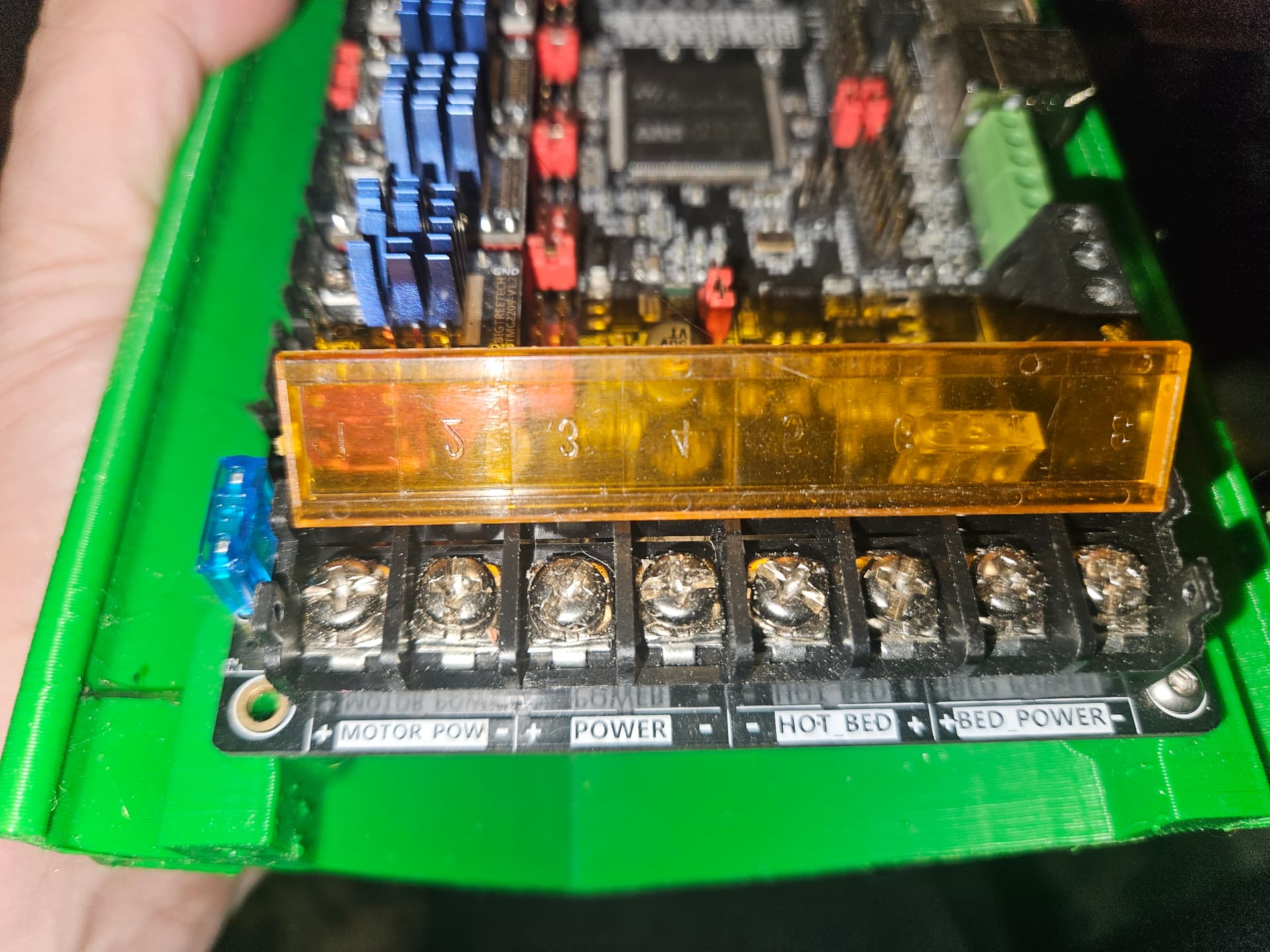
… you will want to disconnect the “Hot Bed” and “Bed Power” wires…

1 Like

Holy Crap! Thanks for pointing that out, I completely missed it. I glanced at the first two and the last one, and missed that the third was reversed.

I was thinking initially to wire the bed outlets up to possibly use for other outputs in the future, but your “less to go wrong” point rings true (especially after seeing the reversed polarity). Wire snips and screwdriver, here I come.

1 Like

You can leave the “Bed Power” connected. The “Hot Bed” is the output to the heated build platform, or “Heater 0” for Marlin. You can use that for a relay control.

2 Likes

Looking great! Have it make its own robot noises!

Soldering seems like the best plan. I think several other people (myself included) have done this.

2 Likes

yes, but really not needed or used.

2 Likes

Its looking great!

3 Likes

IT’S ALIVE…

Powered it up and ran it through some initial movements. I had a couple of issues:

Several of the motors were wired backwards, so I had to flip the connectors (no big deal, somewhat expected)

When I sent the first Z command to move 1 mm down (Z-), the Z2 (rail side) motor zoomed all the way to the top (wired backwards explains the direction, , but the runaway is still a mystery). I had to scramble to unplug it quickly. On that movement, the Z1 motor either only moved 1mm, or didn’t move at all.

I had another time where both Z1 and Z2 crashed again (at least in the right direction this time), and several attempts where any Z movement responded with “Error: Print Halted - Kill Issued” message. I also had a weird issue where commands to any of the motors (X, Y or Z) from the LCD screen would only allow a single movement +/- from starting position (if set to 1mm, it would move from 0 to +1, and then back to 0 and -1, but would not move to + or - 2).

I unplugged everything again, checked all of the wires, and discovered that the Z1 wires were misaligned, and only connecting to 3 pins (photo is an example, it was actually the Z1 pins).

Once I corrected that, everything seems to be working great. I can home on all three axis, all of the endstop switches (including the touch plate) appear to be functioning properly (all LEDs working properly, all M119 commands showing correct status when activated or idle).

There’s not much point in doing the square test at this point, as I will be moving it all to a full size sheet of plywood in a day or two (more likely a week or two, at the pace I’m going), but I do sense a crown drawing in my near future.

2 Likes

It’s not clear from your description. Did you unplug power to your board? (If so, do you have plans for an e-stop button or at least power strip with a switch?)

If it wasn’t unplugging board power, and you unplugged your stepper cable- that’s a really bad idea. Unplugging powered stepper motors is a common way to blow drivers.

No, I unplugged the power cable when it happened, and did so any time I opened the case to work on the wiring (along with waiting a minute or so to let any stored energy dissipate).

So far I don’t have plans for an E-Stop, as the cord connection is fairly conveniently located for unplugging, but that may be something I will consider for the final build. I’ll probably look for a way to include the router power to the same switch as well.

1 Like

I just have a power strip for everything screwed to the front of the table. I use that toggle as an estop. It is much easier and stops the router too.

3 Likes

That is an awesome looking machine. For what it is worth thank you for the details and documentation you have done on it. I wish I would have looked at your post three days ago. It would have answered a lot of the questions I have had.

4 Likes

LOL, before I began I read every post in the LR3 forum going back 18 months (and I’ve kept up on every post since). It took me several weeks, but man, the amount of ideas, inspiration, suggestions, trouble-shooting tips and just great information was incredible. It saved me so many missteps in my build, I can’t even imagine how I would have got this far without doing so.

5 Likes

Now thats dedication. I thought I read a lot of them you win!
I am finding the forums are more helpful than I ever thought, but still have trouble finding exact things I am looking for.

Well not much progress to report over the last two weeks.

I did manage to draw out my first creation using the LR3, but it’s not something that I’m going to frame for posterity…

The boards on my temporary support platform were rough, warped, bent, and generally unsuitable as a surface to draw on, and in my first attempt at EstlCAM I neglected to set the travel Z height properly, but I was rushing to get this drawn for an entry to win a new Kobalt router (sadly I was not one of the lucky few), so I suppose I shouldn’t feel too bad about the result.

I managed to get to the lumber yard and pick up a couple of sheets of 3/4" ply (factory grade), and after tossing a lot of ideas for a table design around, I decided to scrap the idea of building a torsion table for now, at least until I get a few hours of cutting experience behind me.

For now I have set up a single sheet of plywood as a temporary work surface, which should allow me to cut out my aluminum struts for the short gantry, as well as aluminum XZ and YZ plates to replace the printed ones I’m using at the moment.

I’ll build a basic full size table over the next few weeks, but with holidays fast approaching, that may not end up happening until the new year.

3 Likes

Well I finally found enough time to get Little Red moving on the larger temporary surface (I can’t really call it a table at this point, just a sheet of plywood as noted above.

I did a quick check for square, and with X = 770 mm Y = 1400mm , the difference between the two diagonal measurements was +/- 1.5mm. Pretty darn close for a first attempt IMO!

Next up was the “crowning achievement”…

There is obviously a couple of low spots on the surface, and I just strapped the Sharpie to the tool holder, rather than using any fancy spring loaded pen holder, so I can’t really expect perfection. But it does prove that Little Red is fully capable of moving around as directed by a gcode file.

I also received an early Xmas present to myself in the mail. I bought a 1/8" Makita Collet and a whole bunch of various end mills from Sienci Labs. I was going to buy from the V1E store, but with international shipping and the usual costs and delays associated with that, it was faster and cheaper to get them from Sienci, who are conveniently located in Canada.

So I think that I’m almost ready to start cutting the aluminum struts for Little Red. I might try to shim up the plywood in a few places to get rid of some of the worst low spots first, and with Xmas madness just around the corner, it may be some time before I actually get cutting.

4 Likes