There is a jumper to choose high or low.
No
The signal is 3.3-5v you can use a 24v mosfet if you want because those switch the ground and we do not use the positive side… You are kinda interchanging some words here I think.
1 Like
Don’t ever apologize for trying to learn things…or for trying to be safe while doing it ![]()
2 Likes
Relay 24V in from power supply.
relay signal in can either be trigger by a high (3.3-5V) signal or a low (ground) signal. All the regular pin on the board are 3.3-5V and would trigger high. The fan and heater pins you would use the negative side and triggers low.
The mosfet triggers are easy because they are already defined typically and no firmware edits are needed.
The caveat is you need to find one that does not do odd things when you power up. Some trigger for a second and others do not.
As you can tell, even though english is my language, im not very good at that either. (this is the first time ive ever commented on a forum, and im 36 years old lol)
Sorry I missed this part altogether. No worries at all. That is why we are here. I don’t know any of this stuff Either. I buy several in case I screw up and when I figure it out I share it here. Unfortunately I have not written or drawn anything up for the relays yet as I am under the gun to ship RMRRF machines ASAP…then I will do something more formal.
Not surprised, but the led’s are brighter after switching to 24V from power supply…
If I use the FAN2 (-) as a trigger (I’ve been calling it a signal, not sure if that is technically the right word), I’m assuming this requires firmware edits, this is also a low trigger.
If I use a high trigger with a 24V mosfet with a regular pin from the board (can you define what a regular pin from the board is) is because based on the board construction it can have 3.3V, 5V, or 12/24V.
Personally i would like to have a setup that does not require me to change firmware because im totally new to doing such, but im also new to mosfets. Based on my internet search this is a mosfet…
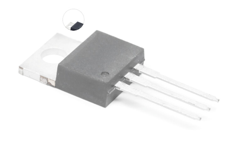
or this is a mosfet…

How would i integrate this into my setup… or is it easier to use the low trigger that you have pointed out, and edit the firmware?
Honestly i learn more when it is not spelled out
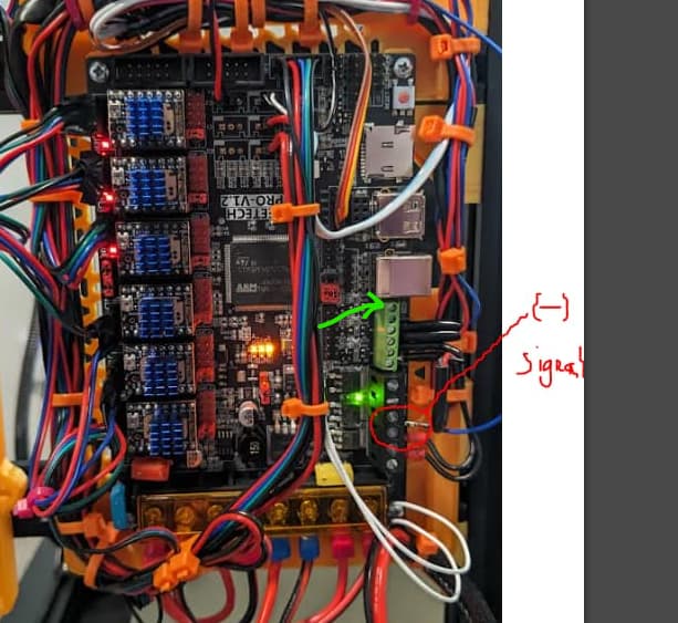
If you use one of the heater pins the mosfet is already on the board. I believe they are there for the fans as well. But the pin Ryan has circled in his picture is a heater pin and works great. Same basic thing I am using from my Manta. Use the - side and set your relay to trigger low. Once you pick your heater pin to use post the pin number and one of us will try to help you with how and where to set it in the firmware.
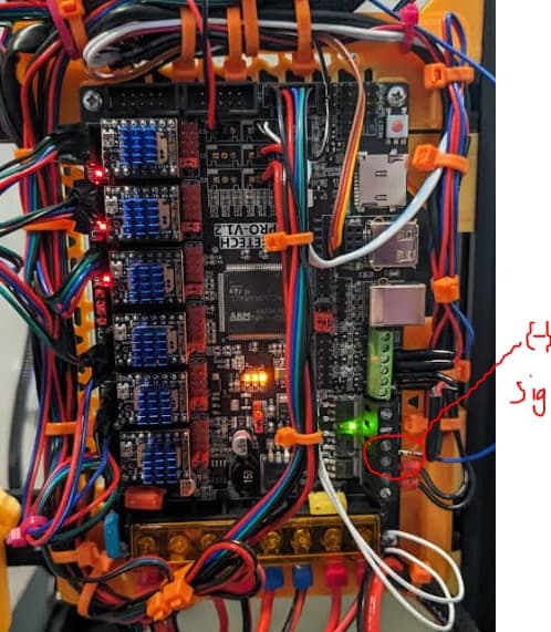
I am using the exact pin that ryan pointed out now
1 Like
So after switching the relays to power supplied from my 24v power supply, I left the trigger wire in HEAT1(-) from my board just to see what would happen… before switching to the pin that ryan suggested. And my relays are set to switch high
Trying to upload the video I took just now… looks like due to the size and format its a zip file for now
When I move up the Z axis during home function and kill the power, the print bed does not drop fast, it drops nice and slow like intended. So now my question is why is it working?, I have not changed anything in the software? It slows the drop when I kill power but will it do something weird when I try to print…
FYI: by Z axis does not yet home all the way because I am in the process of updating firmware to account for the fact that my build space is 300X300X400… Hence the error when I am using my homing function
For video you have to upload to YouTube or something similar and then post a link
@Jonathjon, @orob , and @vicious1
Here is the video…
-
This is using 24V from my power supply, to power the relays.
-
The relays are on HI switching setting
-
I have my signal wire for the relay (switching) coming from HEAT1 (PD1-4) negative pin using a SKR Pro 1.2 board with MP3DP V4 firmware from the V1 docs (thanks to @orob for pointing me to the right place"
I was going to update my switching wire to the fan pin that Ryan suggested but first I wanted to see what would happen with this setup 1-3 above.
FYI, i have not reconfigured marlin in any way from the V4 firmware. This is why my home function errors out, since my Z build volume is 400mm
This is the first video i have ever put on youtube lol…

Sounds like the brakes are working when the alarm kicks in. I don’t understand why your z isn’t making it to the top, but once you get that fixed, it should be ok.
In Marlin you have to specify the Z height. Default is 200 I believe. So once it goes past that it errors out thinking the probe isn’t working. Once he sets it to 400mm he should be able to home no problem.
It looks like the way you have it wired as long as your power supply is on then the brakes are disengaged. For marlin that should be fine. Not so much the case in Klipper LOL
2 Likes
wow, so looks like I can move on to the next project, updating my machine in marlin…
I have spent quite a bit of time researching how to use platform IO, and I found the area of code the sets build size.
The only thing I was trying to figure out next is how the home function is coded, I want to make sure with my increased Z, and Y from 200-300 that it is using 1/2 of those dimensions to calculate the center position for home.
It is a little bit noisy, but really the only reason i wanted the brakes is so that when i shut off my machine it does not slam to the bottom and mess with my leveling
if you want it to be quiet, buy 3 more relays and short the other motor coils and you won’t hear it at all.
1 Like
they are pretty cheap, and considering the time and money I have in this thing already, might as well. I already have all the wiring parts I would need.
@vicious1 I also noticed some new items in the shop for 3D printers!

Is this probe better than the BL touch, I’ve had issue with the BL touch pin not having enough clearance in the probe to move as freely as it shoud