I am sure they are about the same. I have never had issues with either, the Micro probe wins for me because it is very small
1 Like
So I realized while bed leveling, and trying to run some initial prints, that when i kill a print in marlin it disengages the Z steppers, this makes my current set up of the Z brakes not ideal since the way i have it set up only “engages” the z brakes when there is 24V power. So when i kill power z brakes work great, however when i kill a print they dont come on at all.
How would i change my setup to engage the brakes once a print job is killed?
For that I believe you will have to set it up how @vicious1 suggested. I’m sorry I am really no help for how to set it up in Marlin. If you were on Klipper I could walk you through it easily lol
1 Like
How are you “killing” the print? If you are hitting the reset button on the screen it is resetting the board, that means you need to choose a pin that acts accordingly.
If you are hitting stop print you can adjust the firmware so it does not disengage the steppers (it should not by default if you are using my firmware).
You need to also use a trigger pin, if you want it to work under all circumstances.
Something isn’t quite right with the setup. With the trigger pin hooked up to the negative side and the relays set to HI switching they should never switch. They need to be set to low. But I also don’t think he ever set up the firmware to trigger the pin low either. Or does the heater pin give off some positive voltage until its pulled low to activate??
Another reason I hate low side switching.
JJ has this correct.
If the host side is using a GPIO that low side switches a FET, then you need to have the relays configured to see their returns switched instead of the high side.
The issue we are having on the other board with high side switching is the correct voltage. Some boards are 3.3v, and some are 5v logic. Either a relay needs to be found that handles both or we low side switch.
The other relays we have configurable input high/low.
Why would high side switching be better?
We have two options being worked on and tested now and I don’t fully understand why you hate low? I am not sure of the right answer but low seems easier.
1 Like
It sounds like there is no trigger pin to me.
I could be very wrong. But aren’t most of the boards hot on the positive all the time and do all the switching on the low side? If that’s the case even if he had the relay set for high side switch it would just be always on correct?
I’m wondering if he isn’t hooked into the positive side by mistake and by it being set to high switch as soon as he turns the power on the relays are switching. That’s the only way I can see it working with no trigger pin set up. Otherwise the relays would power up but not switch. He would get the green led on the relay but red would stay off until he triggered it.
I am hitting stop print. Which i initially did not expect it to disengage the Z steppers,
This is true, i do not have a trigger pin set up
Ok I didn’t think so. So whats happening is either you have the trigger wire on the + side and thats feeding the relay, or the negative is floating and triggering it because you have the relays set to high switching. At least thats my best guess. hopefully @vicious1 and @MakerJim will have a better correct answer for you. Then I can learn along the way as well lol
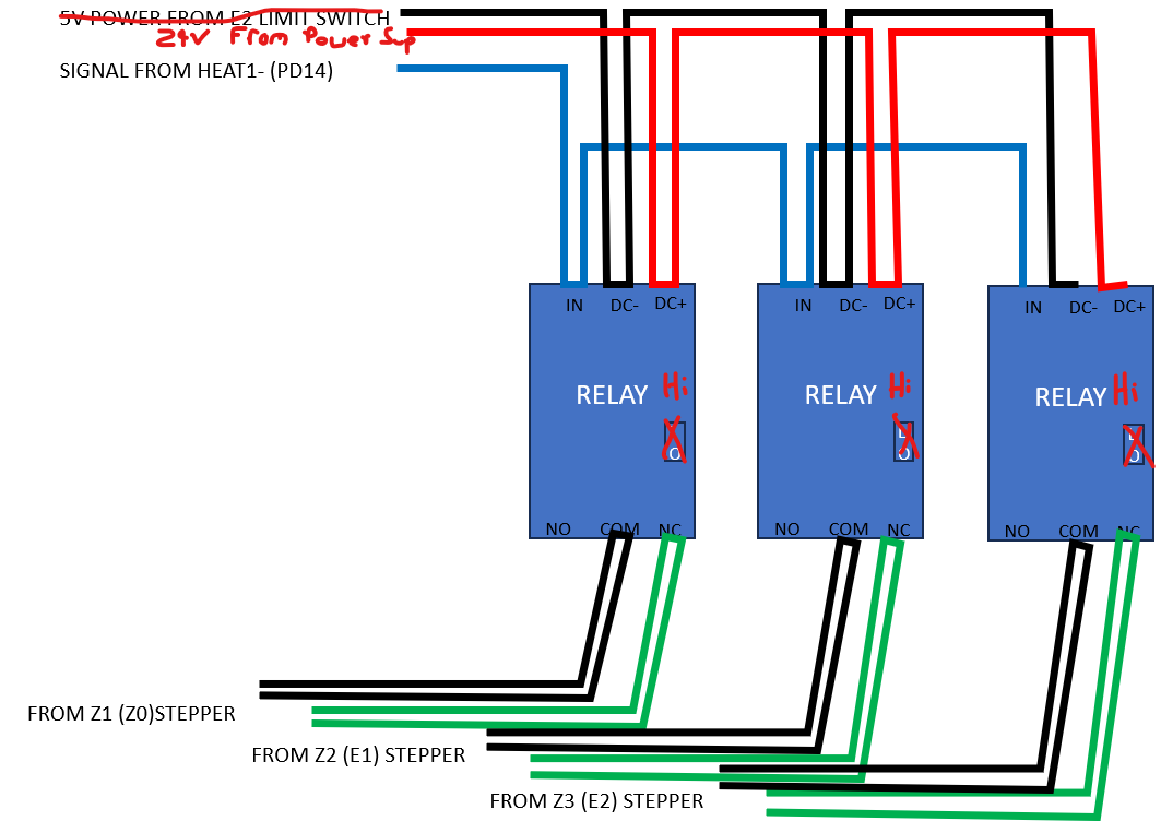
@Jonathjon This is how im currently set up… So the Z brakes work when i cut power, but do not work when i kill a print (hitting the stop print function on the TFT print screen). I though just the power cut of would be all i need, but then i found out that when you cancel a print in marlin it disengages the Z steppers.
I have not changed anything in the firmware
now i understand with greater appreciation the whoppy. needed this while trying to get bed leveled for the first print
1 Like
Right I understand how you have it set up. And if the relays were set correctly to switch low you shouldnt be able to move the bed at all without having the pin set up in firmware. So while it is sort of working now, its not how its intended to work. At least that is my understanding
Marlin does not have a way to clone a pin like klipper, so you need to edit your firmware so the steppers do not disengage when you stop, it is in configuration_adv. This means when the power is on the steppers are on. Then the trigger is not needed.
Currently I can’t think of a way to add a trigger other than splice the enable pin for one of the Z steppers.
Thats right I forgot you cant clone a pin in marlin. So yep need to make it where the steppers never turn off unless the board loses power. Then the brakes will work as intended
1 Like
Thanks @vicious1 Im starting to get a pretty good handle on to edit firmware, so ill see if i can get this to work.
Going to try to get a print in today before i change the firmware again because i itching to see its quality
1 Like
close older topics to help with spambots, and faster new user questions.