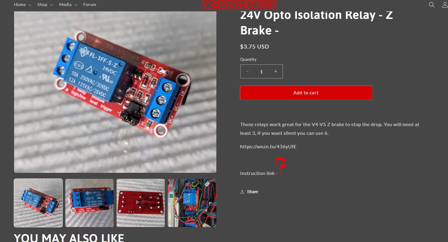
I am working on integrating Z brakes into my build, however trying to find a schematic for using the 24V Opto Isolation Relays that Ryan provides on the V1 engineering shop.
Looks like a link may be missing…?
I am working on integrating Z brakes into my build, however trying to find a schematic for using the 24V Opto Isolation Relays that Ryan provides on the V1 engineering shop.
Looks like a link may be missing…?
I should have mentioned that im building a V4 with SKR board and 24V power supply
There is a thread called use z-brakes that has the schematic on it.
Any reason you aren’t building the v5?
The V5 was still being developed when i started the V4, and i had to rebuild all the CAD since i was targeting a build volume of 350X350X450. This required additional reinforcements, and some other tweaks. It ended up being 300X300X400ish
That schematic does not look like it is for this particular board, I purchased 3 relays based on the comments Ryan has in the shop. Not sure how these 3 relays can be integrated based on that schematic. Basically looking for the schematic that explains how each of these relays are spliced in
I figured you had your reasons. I was just curious.
The simple relay method you have chosen shorts one of each motor coils to itself in the normally closed position. Pick 2 wires from one side of each plug. He took the black and green. When the relay triggers, the coil is disconnected from itself. Your board should have a 5v out power pin for an end stop and a ground you can use to power the relay then pull a pin from the lcd header that you can set to switch when the z motor driver enables. Wire all the relay enable pins together so they trigger at the same time.
I understand the first part, just a few questions on the part above…
So the relays are powered by 5V, can they be powered by more than 5V, say 24V, and what would be the difference for the relay?
I ask this because in one of the images i remember seeing you were powering the relay with 24V power, and the schematic itself shows 24V powering the relay.
Can you explain to me like im 5, what you man by “pull a pin for the lcd header that you can set to switch when the motor driver enables.” and what do you mean by set, is it somthing that i need to modify in the firmware?
You can get these relays in a variety of operation voltages. The ones I got from Ryan on my V5 operate on 24v so I used a spare heater pin to control them. I believe @orob uses 5v to trigger his relays. Same idea just needs a 5v pin instead of a 24v pin.
Great question. I tried to to do 2 things with the z brake setup:
so there are both 5V and 24V relays in my design. After looking at it, it might be overkill for the 24V relays because the 5V on the board also comes from the 24V source, but you can have 5V from the USB if not jumpered correctly, so it is an attempt to cover both power loss scenarios.
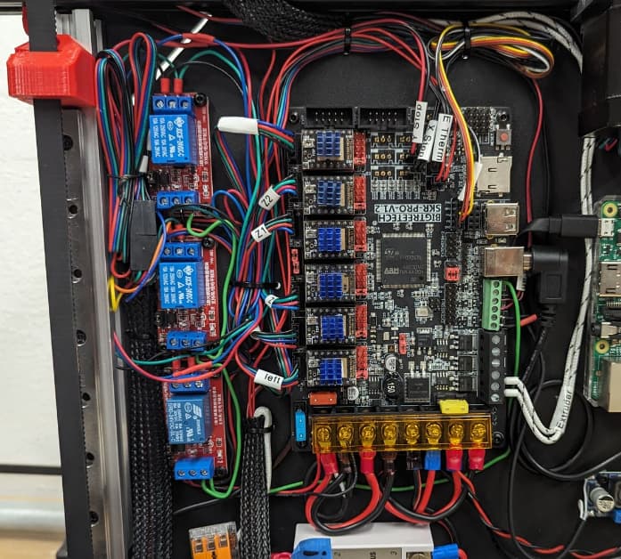
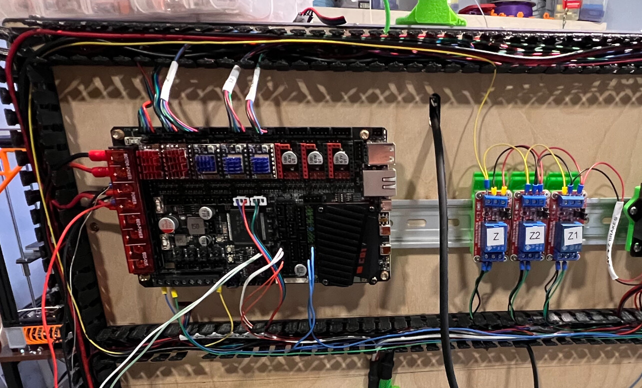
So I have power from my relays being supplied from the open limit switch pins I have available on my board. And I have pulled the necessary wires out from the motors to wire the relay in series with the relays.
The part that I don’t understand yet is how to control the relays.
What triggers the relays, I see in one of your setups you have a yellow cable that goes to the input on the relay. Is there a function I need to set up in the config file to trigger the relays on and off or is there an open pin on the board that preforms the triggering function required
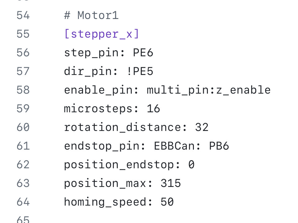
Here is how I have mine controlled in my printer.cfg
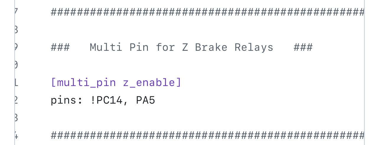
On the X motor I took the enable pin and changed it to multi_pin
Then I added a multi_pin section and included the enable pin for the x motor and the heater pin I am using to trigger the relays (where my yellow wire hooks up)
On a home the X always triggers first so that makes sure that when the Z motors are enabled the relays are already opened there is no short seen by the tmc drivers.
Note my PIN numbers might be different than yours depending on which board you are using. I’m running the Manta M8P V2
I should also mention that I am not running Orobs board, but running the 24v relays that @vicious1 sells in the shop. Ultimately it should be controlled the same way if I understand @orob board correctly.
Thanks you for this explanation @Jonathjon , This should help me get closer to the finish line with this printer add.
I’m a mechanical engineer by trade and I started this printer project after completing a lowrider and seeing how awesome the V1 community was. I wanted to challenge myself to get into more of the electrical and software side, electrical is not new to me ( nowhere near an expert though), but software is still very new to me. So I have lots of questions, try to work through them as much as can on my own first, but at some point advise is needed to gain new momentum.
Anyways just wanted to say I appreciate the help I received from this community especially the software stuff. I’m learning new shit every day almost, it been a very rewarding experience.
@Jonathjon I’m also running the same 24v relays the @vicious1 sells. So was concerned they would not function correctly with only 5v supply from the pins I have been using on the board.
Is there a performance decrease when using 5v on a 24v relay instead of the full 24v?
Curious. I have bees setups that run a fourth relay, what is the function of additional relay to what I have been working on with the 3?
Are you getting your 24v power directly from your power supply or another auxiliary device?
This sums up my last 9 years. I love it.
I forgot to mention this before but make sure you set the jumper to low side on the relays. That will make them work no problem. They get their 24v positive and negative from the power supply and just the ground to switch from the board. And they trigger no problem at 5v with the jumper set to low.
I’m glad I was able to help! I had to ask a lot of the same questions when I set mine up and @vicious1 was a huge help as always. I’m just glad I was able to take what he taught me and pass it along to someone else. This forum has been a wealth of knowledge and learning for me and I know so many others. I’m glad you are finding the same.
Also this forum is always helpful. I joined a German woodworking forum and some of the older members are so incredibly arrogant. I am so glad I was here first so I know there can be non-toxic forums. ![]()
This forum will spoil you for sure. I don’t know any others that are as helpful as this one. That’s why I come here for just about everything lol.
The 24v relays should be connected to the main board input power and switch when it switches. this was why there is a 4th relay on the other design. If you add a 4th relay that has a 5V coil to switch the 24V relays, then you can use a 5V pin triggered by the board. I don’t know how to do this in Marlin either. In marlin, the brakes are not as critical because falling is much less of an issue because it doesn’t shut off the motors each time you change the configuration. Typically there is a G84 at the end of your gcode file put in by the slicer to shut off the motors. If you remove that G84 motor shutoff command and have the bed go to its lowest point (max Z) at the end of each print then it will only drop the last little bit when the power is cut or you manually turn off the motors when there isn’t another planned print.
My relays have a 24v + and - coming from the 24v power supply and a negative coming from a heater pin to trigger. I only have 3 relays. This was how Ryan suggested I hook it up and it has been working great for me. Only issue I had was trying to use the Z to trigger the relays. It wasn’t fast enough. But by switching to X then no matter what it will always trigger first before Z so they are ready to go.
the heater has 24 coming off off it to trigger it. so that works. the enable pin to the 2209 was 5V, so that was what I used.