Yes I follow you now. My bad. It does work out well that you can have either 24v or 5v relays and still get the same effect. I came close to using an 8 channel relay board I have just to try out shorting both coils. But I was extremely pleased with how it did with one coil shorted. Will be installing them on the V4 real soon. Hopefully these 2 skr desk ornaments I have will be the only 2 I end up with LOL
I wonder if the desk ornaments just need new regulators or if the cpu is toast
From this post I ordered the parts that were suggested and have them at home. But I just don’t think I have near enough experience to make the part swap my self. And then really no way to know if anything else is damaged either beyond that. I know for a fact that chip on both boards is toast. Makes a nice bic lighter sized flame when it happens LOL.
I did that with an endstop miswire. The repair attempt pulled the pad of the regulator off the board
Yeah that one is just in a spot that’s not worth me even attempting to repair. Talked to @MakerJim about repairing it but I know he has a ton going on so I didn’t want to keep bothering him with it.
At this point if another one goes I’ll just replace it with a Manta and be done with it. So much nicer not having to have everything separate
What size wire and pin type are you using for the 24v power. I ask because on the octo relays the input port is pretty small and you have to double splice a lot of the wires, don’t want the wires to heat up to much.
I think it’s 24 or 26. I can’t remember for sure but it’s not big at all.
I’ve been distracted the last month with some family members’ having health issues.
But, I’m back slowly to catching up.
I’ve had some success fixing up some other boards that I came by- so if you’d like me to attempt to rescue a board- I"m game to try that. For the learning experience, no guarantees of success.
24 or 26 are too small, even for just board power if you’re not running heaters.
I just picked up some fork terminals off of amazon- I’ll make some test cables and if I’m happy with those, I’ll paste a link.
I’m about to start prepping an SKR pro that I fixed from a batch that I came by- and was going to use it as my Klipper test bed and maybe as a controller to finish out my stalled Repeat V4 as I instead build up a V5.
I get that for sure and I am in no rush at all. They are not currently needed for anything. I did order those parts so I can send them to you when I get back in town at the end of April. And I expect no guarantee at all.
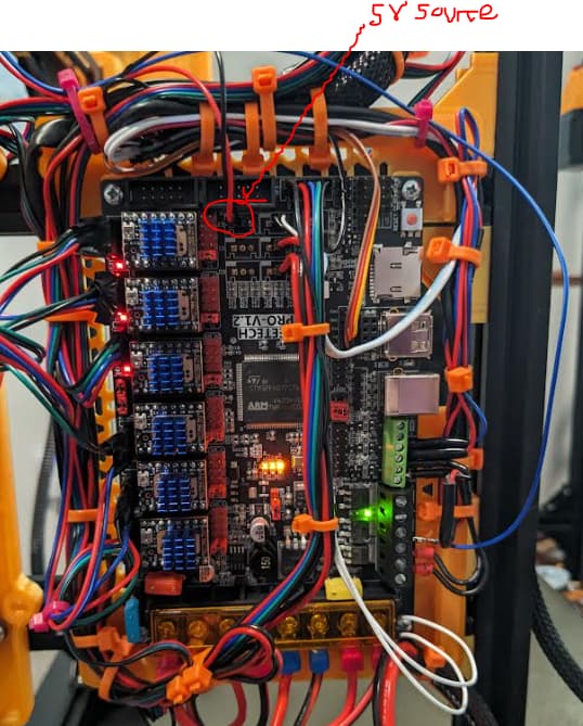
I looked again at what I ordered, Its 22. But this was not for board power. It was just to power the 3 relays. Board power is coming from this
It was working good for the little bit of testing I was able to do before I left. If I run into any issues I will replace that power supply with a meanwell 24v. But with mains powered bed heater I shouldnt need that much power.
Ok, first off, don’t judge my wire management, its a WIP since I tore up a lot of it to put in these Z brakes. I plan on cleaning this up once I’ve proven that everything is working properly, then ill re-wire, mess something up and have to go through all my checks again lol.
This is how I think these relays should be wired up based on the help from forum, particularly @Jonathjon and @orob
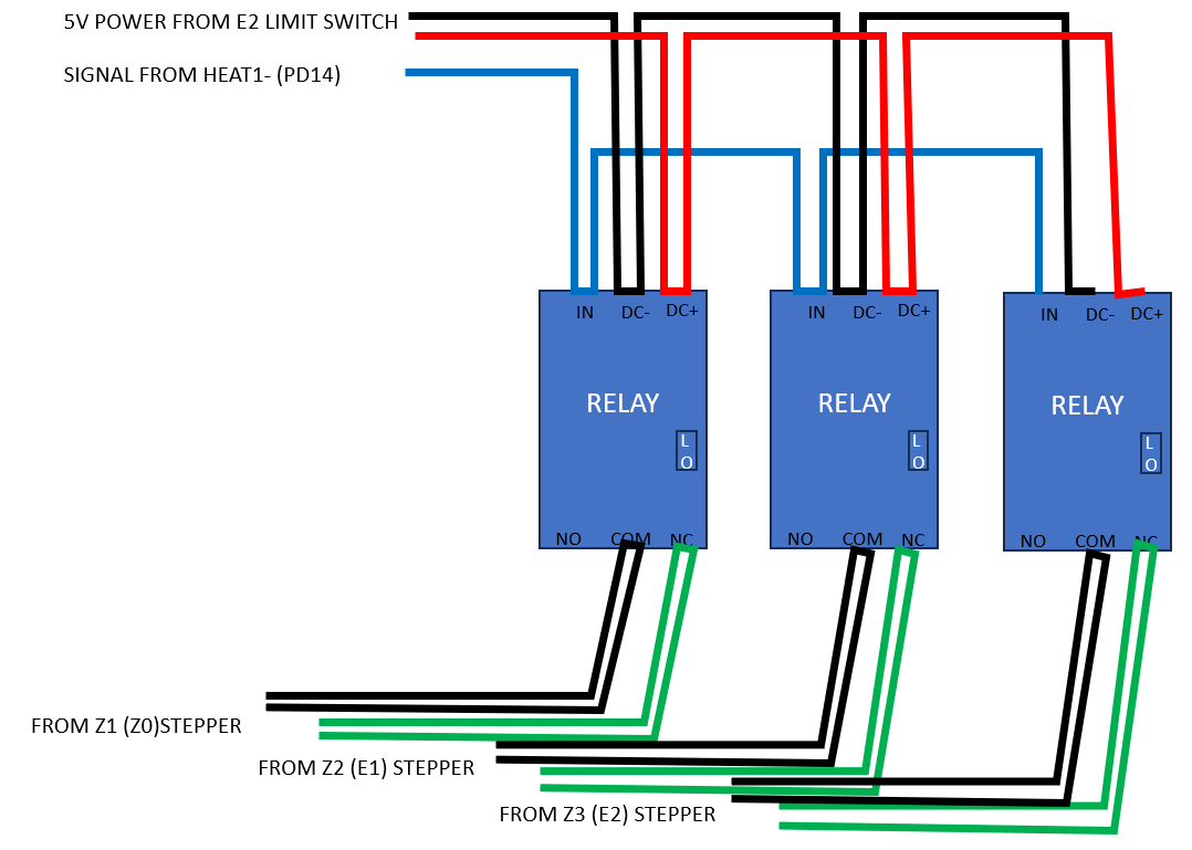
I decided to power the relays with 5V source from the boards empty limit switch ports, I was worried about running 24V power on these smaller diameter wires, and from what I can gather from the steppers themselves, 5V should be sufficient. And I think this should work because limit switch power using the pins I have chosen from the board should always be on when the board is on.
I thin used the HEAT1 (PD14-) for the signal source

Assuming all this is correct, I think I can now try to break stuff in Marlin.
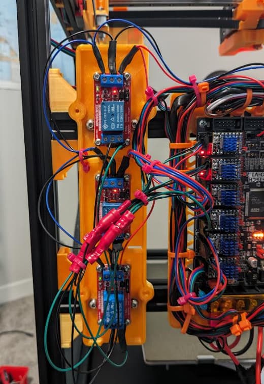
Once my new connectors come in from amazon, ill clean this up, looking pretty ratty atm. My dream is to build a harness from scratch the right way for my entire rig, but that may be a pipe dream for the time being
if the relay coil says 24V, then power it from 24V. If it says 5V, then the 5V from the endstop is fine. Don’t those relays have a trigger pin and + and - power for the relay?
1 Like
Meanwell 24V power supply is what I have chosen as well mostly because I remember some of my electrical engineer collogues saying that this brand will have fewer issues than the cheap ones off amazon.
1 Like
The meanwell is what I have on my V4. I went with the smaller one from Ryan for the V5. He is going to do some current draw test and make sure we aren’t asking too much from it. The little bit I was able to run mine before I left it was doing fine
The relay is 24VDC, but can I not use 5V to power it when the relay is in its low level trigger mode?

Until I get better connectors to use larger gage cable for 24V power directly from the power supply i figured this 5V setting was enough to prove out its function
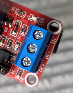
DC+ is 24, DC- is ground and IN is the 5V trigger pin from the control board. I think you have it right, we are just misunderstanding the descriptors of the setup.
Oddly the higher the voltage the thinner the wire needed. No worries though they draw very little current so it does not matter. But if it is a 24V relay you need to give it 24V, the trigger pin is 3.3-5V.
1 Like
So in my description im powering the relays with the power coming from the empty limit switch I have circled in that image above, and switching coming from the heater pin, which is 24V.
The lights i expect to be on, on the relays are on but what is sounds like is.
- I should change my DC power going into the relay to 24V from the power supply instead of from the limit switch pins.
- I should change my trigger setting on the relay to “High” instead of “Low”
So if the trigger pin is 3.3-5V, then I should not be using the HEAT1(-) pin to trigger the relays since that pin is 24V?

- agree
- depends on how you have it wired.
When the system is powered down, you want the normally closed (NC) pin wired so that you have the motor coil shorted by default. These relay boards can be purchased with switch high or switch low. I believe Ryan’s boards in the shop are switched low, so Low would be likely the trigger for you.
signal should be from a 5V IO pin like one of the end stop signals or the TFT TX1 pin works (if not using a marlin touch screen).
Ok, I think I understand now, Need to for sure, update my power wiring to some from my power supply, and I can keep my signal coming from the HEAT1(-) or PD14(-) which is 24V as long as I keep my relay set to HI and now LOW.
I promise I know stuff, ask me about materials or mechanical stuff and im your guy, I just slow this electrical stuff (still learning) because im being over cautious. Im over cautious because for my day job i build li-ion battery enclosures and have seen some shit ![]()
1 Like