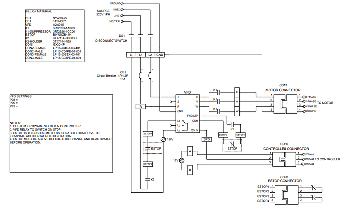
I don’t have practical experience with a VFD, but I’ve spent some time with laser control and poking round in the Marlin configuration files. In Marlin, you have to select your ‘S’ value representation. You can select from PWM, Percentage, RPM, and Servo. The V1 maintained firmware uses PWM, which works with lasers, but for spindle control, I believe you will want RPM. In practical terms, that means the same firmware (given your VFD) cannot be used for both laser and spindle. If you want to run both a spindle and laser on your machine it is highly likely you will have to reflash your firmware when you make a swap. Fortunately, that is easy on the SKR Pro.
To match up your VFD to Marlin, you will need edit the Spindle and Laser control section of configuration_adv.h. Here is my educated guess on what changes you will need to make.
First, you will need to enable spindle control (and perhaps disable laser control) by editing these two lines:
//#define SPINDLE_FEATURE
#define LASER_FEATURE
Then you will need to change what the S values represent in M03 and inline commands to RPM in this section:
/**
   * Speed / Power can be set ('M3 S') and displayed in terms of:
   *  - PWM255  (S0 - S255)
   *  - PERCENT (S0 - S100)
   *  - RPM     (S0 - S50000)  Best for use with a spindle
   *  - SERVO   (S0 - S180)
   */
  #define CUTTER_POWER_UNIT PWM255
And finally you will need to setup how the PWM values sent to your VFD map to RPM in this section:
  #if ENABLED(SPINDLE_LASER_USE_PWM)
      #define SPEED_POWER_INTERCEPT       0    // (%) 0-100 i.e., Minimum power percentage
      #define SPEED_POWER_MIN          5000    // (RPM)
      #define SPEED_POWER_MAX         30000    // (RPM) SuperPID router controller 0 - 30,000 RPM
      #define SPEED_POWER_STARTUP 15 // 25000    // (RPM) M3/M4 speed/power default (with no arguments)
    #endif
I think it works this way. In your CAM, you specify some RPM, say 22000. That value is then used in the ‘S’ values for M03 and/or inline commands when the postprocessor generates the g-code, so the g-code will have S2200. Marlin then uses the values in the previous section to calculate what PWM value it needs to send to the VFD for an RPM of 22000.
As for the PWM pin, you can use PC9 for both and simply reroute the signal between your laser and your spindle when you swap between them, or you can attempt to find an alternate PWM pin.
In searching, I could not find a definitive resource on which SKR Pro pins support PWM. I think PF7 and PF8 pins (which are on extension 1 along with PC9) are PWM pins. If it were me, I’d hookup a voltmeter to pins on the extension block and use M42 with an S value of 128 to see if I got half the voltage from a pin. I’m also clumsy, so I’d power down the board between each pin test to avoid inadvertently shorting pins.


