1.5in thick 6061 aluminum plate

Ive cut down to 22mm and the lash has become a big issue… i went back into fusion and dropped the step down by half and reduced the step over.
I retorqued everything and there was minor gap between the tool holder and the frame so i pumped as much hotglue as i could into the gap. I have yet to see that actually flex but you never know.
I may have to have a machinist run the 2 alignment pin holes since they run the entire depth.

I can honestly say i feel comfortable using the machine for 3/4in of material.

End stops, and a probe would make it all a hole lot easier.

Also like what was said about splitting up the cut… that would probably help a lot.

1 Like

I was hoping to add this to the top but apparently you cannot edit comments after like a day?

LESSONS LEARNED…

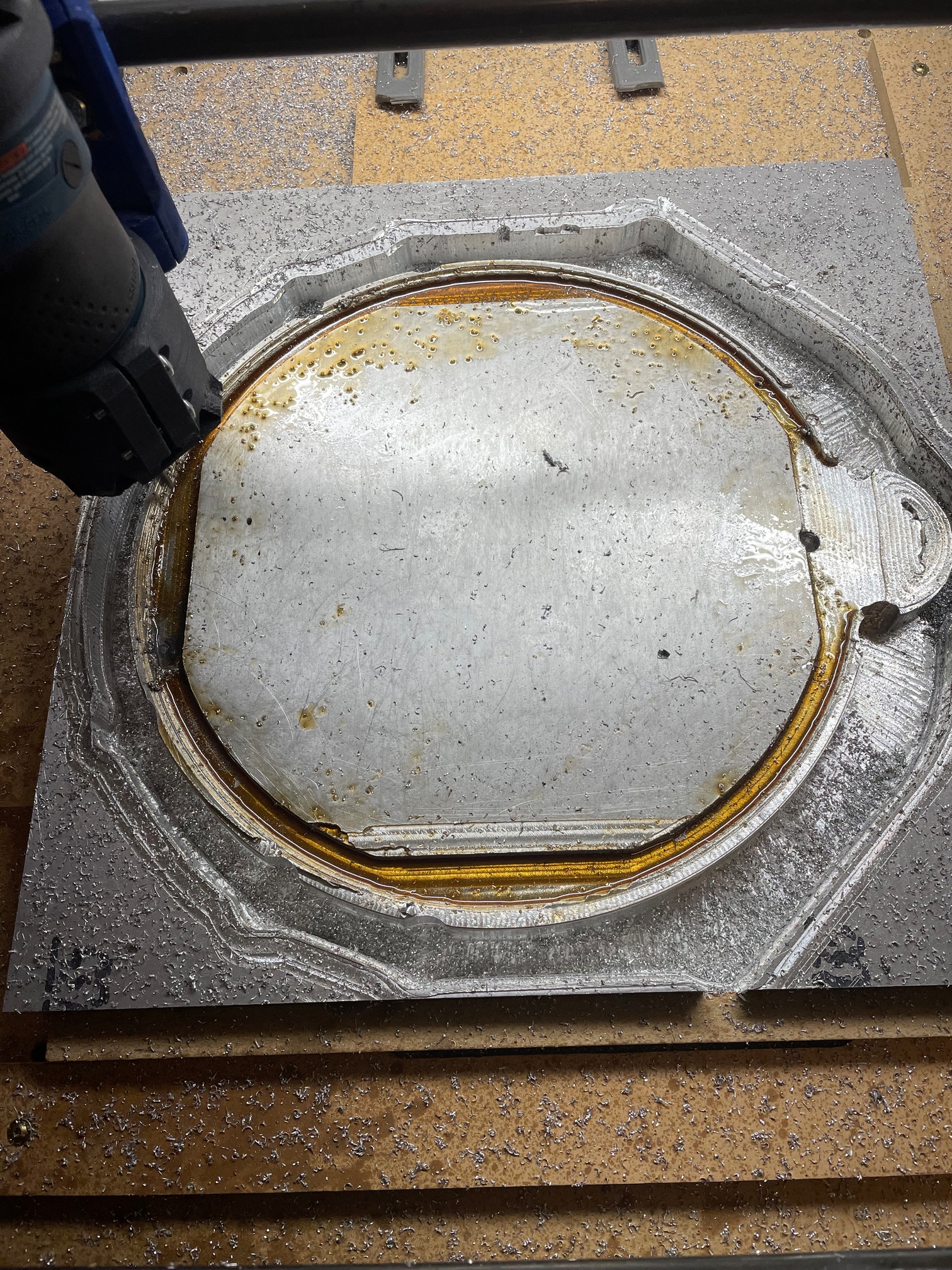
First off, I’ve barely made it through the first adaptive cut… 26mm deep. The initial machine time said 4hrs… it took me basically all weekend.

FUSION 360… In my fusion 360 CAM it wont start an adaptive cut from the origin, it will start in the helix. So I added a contour to trace the upper outside of the part, then it links the 2 cuts and continues from the contour into the correct location for the helix. This has the added bonus of verifying the alignment of everything if its the initial cut.
My post processor adds M codes that seem to freeze my controller, the big tree V1.2 I believe. M84 S0 and M117 specifically. the M117 command is the title of the step so M117 2d Contour and it will be there for each additional step in the gcode.
Because of the intuitive nature of the adaptive clearing, I thought it would be fine to set it to cut the full depth, I’ve since decided that 10mm is about as deep as you should go in a single run. so in my case I have 3 runs to cut my 26mm depth. This has the added bonus of cutting down processing time considerably, from 8mins on some cut to 30second.
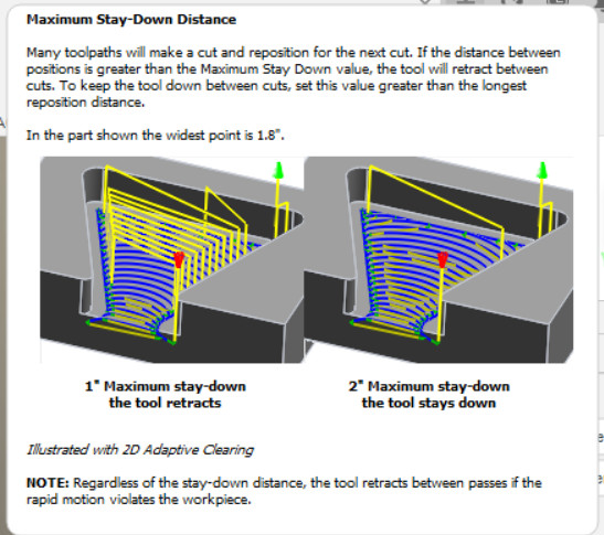
Maximum stay down distance in the linking tab is my best friend. having it too low increases machine time considerably because the tool is picked up and moved back to the other side of the cut rather that looping back. I learned this exploring, I may be the last man on the planet to figure it out.

MACHINE. My machine is ‘huge’, 20x40 cut area. it adds a lot of flex into the mix. when I cut AL again, i’ll definitely install a brace just outside of where gantry will end up moving. a 20x20 cut area seems about the biggest you would want to go without making concessions.
I went thru and tightened everything up in the beginning, and then at 20mm down like 8hrs of machine time I had to do it again.
The plastic parts are the biggest issue for flex, obviously. I use a carbon infused polycarbonate tool holder and once it is below the main gantry bracket the force the tool puts on it flexes it quite a bit. I imagine pla would probably break.
chattering is an issue, simply putting a finger against the router absorbs a lot of the vibration and makes the finish 1000x better.
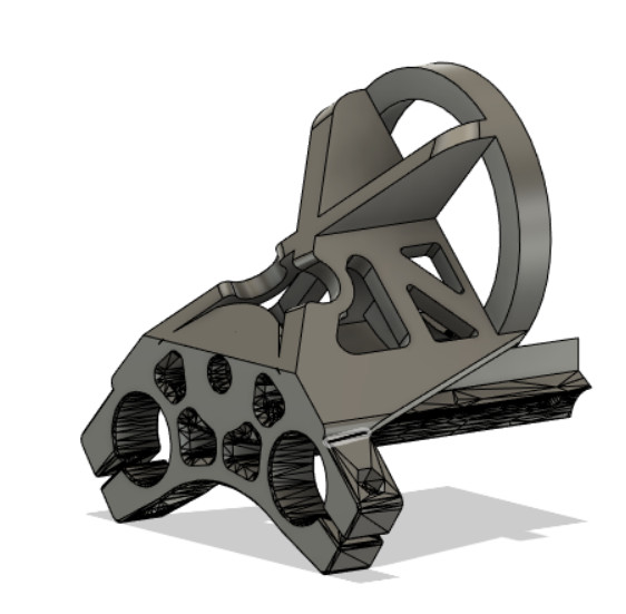
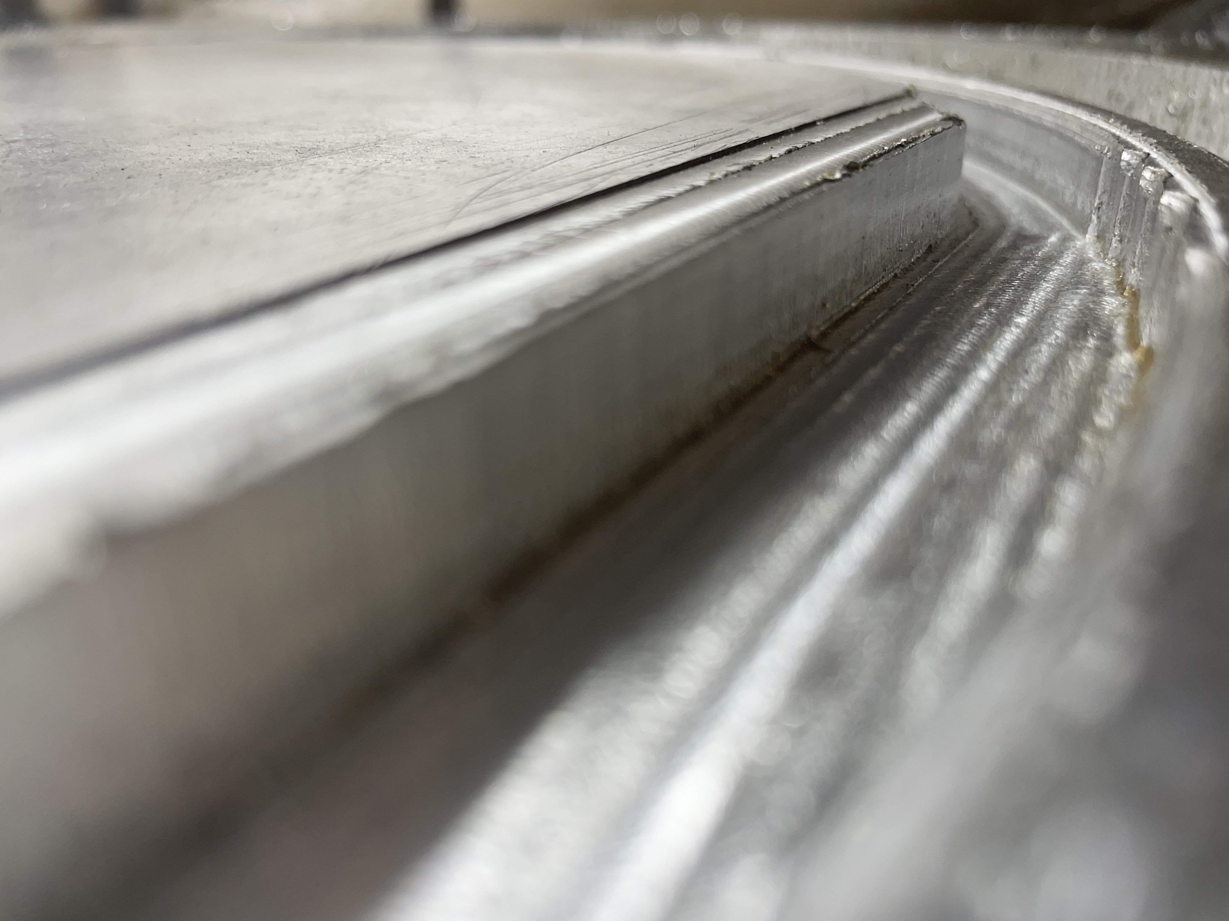
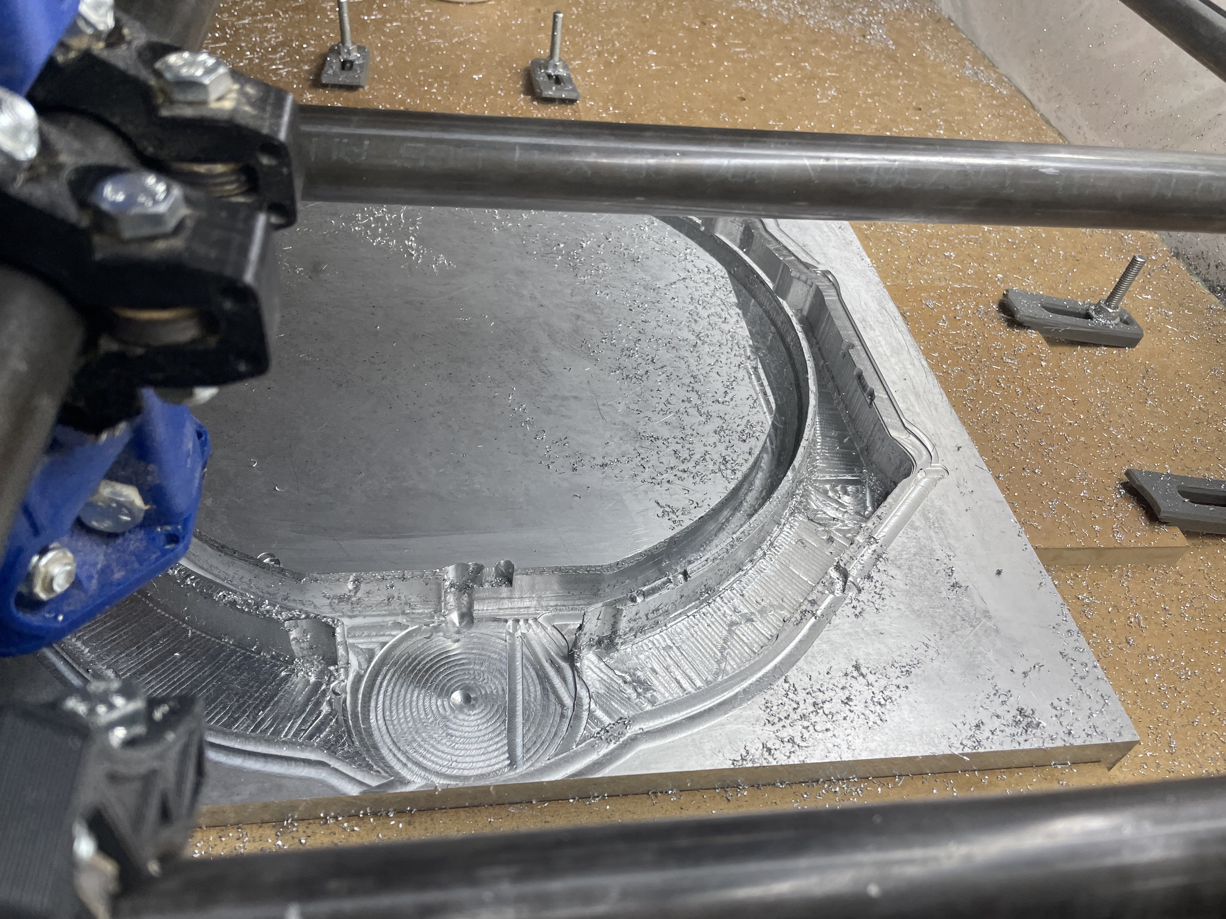
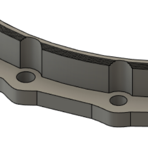
If you can manage it, I highly recommend designing a upper tool holder bracket. at depth I can watch my router move probably a 1/4in when the tool touches the side wall. This actually led to galling quite a bit in the end, the face of the part is as you would expect but the side is nothing but a smear of aluminum in the last 3mm of depth. For the tool holder i would try to do an x brace design to help combat the flex, as a bracket similar to the bottom wouldn’t stop sideways movement by much. When i’m finished with my design I will post a picture. ETA: added my design. its quick and dirty. I stole the Z coupler and graphed my tool mount to it… then added in bracing with respect to what I saw as the machine flexed… this should leave just what is in the gantry, and given if I hold the router while machining it works fine, i think its acceptable… time will tell. PS. yes the reverse Z coupler is intentional. I know it looks funny but it should work.

An airblast seemed to be, meh, if you have one, great! if you dont, whatever. one pass on the adaptive was 17mins. and I had to clear chips once every 10 minutes. part of my machining was done at night and my compressor is 5times louder than the cnc so I would shut it down to appease the neighbors and family. Now tight bore holes could be a different story, my tool seemed to do a great job of throwing the chips though so I dont think it will be.
A nice vacuum is a must. I used a 12gal Rigid shop vac with a reduced 32mm hose, think house vac size. I could keep it back 6in and still pull the chips away from the cut zone. Pay particularly close attention to the way the gantry is moving, I let my hose get in the way once and it kicked the machine WAY off course.
An E-stop on the stepper power was a great help. during a crash i could hit pause, kill the stepper power, and then realign the machine manually before restarting everything.

TOOL… I used an SPEtool 3in long 1/4in wide carbide O flute bit from amazon, of the 2 i’ve had in the machine one chipped but that was after a particularly rough collision and I dont fault the tool.
the bosch colt 1hp router was great, I was able to cut 2mm down and keep a clean finish. I dont recommend that DOC though as the upcut bit will pull itself into the material if it has enough to grab onto.
I’m going to do a contour facing operation here in a bit with a speedtiger 2 flute upcut 2.5in long bit too hopefully clean up the smear, I will post my thoughts when it finishes… or if it fails.

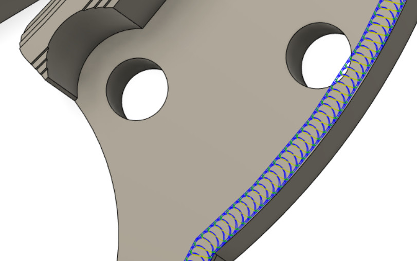
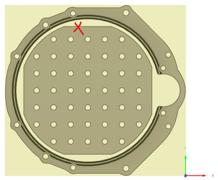
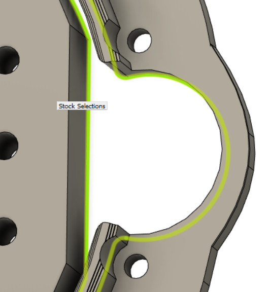
PART DESIGN… I have bolt reliefs in my part, if you can, dont cut features like those with adaptive. almost every one of my crashes was due to those bolt reliefs and how the adaptive machines the trailing edge. a couple contour passes after the initial rough out would have been a much better plan.
image
perhaps increased rigidity in the tool mount would prevent the issue, but I cant be sure just yet.

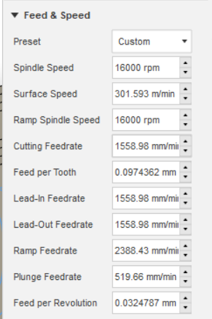
FEEDS AND SPEED… this topic is a lot less rigid in practice… I used the settings below
for Scientists and Engineers
image
Freedom Units
image
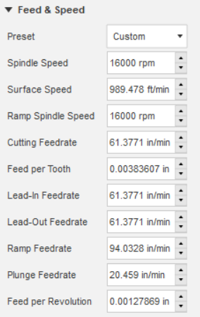
I used a DOC from 2mm, accidentally, to .5mm… 1mm and .7mm were the bulk of the work and they seemed fine. I used the initial settings above and changed the speed on the machine from 100% down to 50% and up to 160% without a noticeable change in quality… I used this to my advantage, in areas where I knew deflection was going to be an issue I slowed it down, and in other areas I sped it up.

FINAL THOUGHTS… it is 100% reasonable to machine aluminum on a regular mpcnc primo. I would say the limit on a basic setup is 1/2-3/4 of an inch. But with modifications I think the limit is tool length/strength. its definitely not a speedy process… I was naïve and thought I could knock out the entire part on the weekend. Pretty sure I’ll finish it around xmas time. 2 wks for those of yall in the future. I’ll keep posting updates as the journey continues, #pokemon, but wanted to get the bulk of the findings out before I forget everything.

PS. I dont have these, but given some of the issues I had I would think a multiaxis probe and endstops would be great things to have.

You can create or use a sketch from your design for this. Add a point wherever you want the entry, then on the 4th or 5th toolpath tab, you can select the point as the entry.

Also, keep your eyes open for “keep tool down”. It works in tandem with the stay down distance. I like it a LOT for contour paths to avoid the retraction before each depth, but keep in mind that if you have another contour starting point inside that max distance, it doesn’t seem to recognize that retracting is appropriate. I got caught rapiding through some cedar at about 1/2 inch deep. Oops.

That’s really pretty deep for a “plastic” cnc in aluminum. Again, caveat that it’s probably perfectly acceptable with light stepovers and close to the gantry (i.e. not too deep).

I think it probably contributed to the flex you saw at lower passes. You’ll see less of that with shallow stepdowns, and you can make up for the loss in MRR with higher stepovers and chiploads (feed) and you can easily push decent tools to 20,000+ rpms.

I’m not sure what you mean by trailing edge, but i use adaptive for small holes as long as they are more than twice the tool diameter. As an alternative to the contour, check out the bore path (under 2d). It’s a great way to finish holes like that, and I also go straight into the smaller holes (less than 2*diameter, but still big enough to helix).

I’m amazed that you are tackling such a large job without endstops. KUDOS! As for the probing, several of us got it working on marlin. The only issue was that using the zmin as probe didnt work, and we had to manually define the pin (even if we defined it as the same pin that zmin is on). That may or may not have been fixed in the last 2 years. I flip my broken tools upside down and us them as probes.

All in all, it sounds like you learned a lot, so no matter what happens with your part it’s probably worth the experience. I know you said it cost around 150-200 bucks (too lazy to go back and find it) so that’s pretty cheap education. Plus, you’ve probably been entertained and challenged at the same time. I 100% agree that the primo is reliably capable of aluminum GIVEN SOME ATTENTION TO BUILD QUALITY. We all know that guy that can assemble an mpcnc but not manage to cut softwood well. That guy should definitely not try to cut aluminum. My burly cut mild steel happily, and now that I’ve resized my primo, I’m gonna try that again.

The only thing I’ll add (since future folk eyeing aluminum will certainly look here) is that good tools make all the difference. I don’t have any experience with the one you chose, but it seems to have worked well. There really is no sense in trying the cheap tools just to see, unless you have a pile of scrap and plenty of patience to work with. I have because I did, and spent more than i should have breaking tools. Spend the 20-50 bucks and be done with it (1/4 in) or else go with those 1/8 kyoceras ryan sells. Those are pretty cheap, really, but still 3-4 times as expensive as the import tooling.

Again, congratulations for learning all this stuff and not scrapping the stock. It’s kind of a big deal.

An update on the importance of rigidity… I tore down the cnc to install the new tool stabilizer… turns out my polycarbonate tool mount split in half just above the clamp ring for the tool. So essentially it was only being held by 2 bolts.
I imagine this happen around the same time that tool chipped as everything went down hill after that crash.
I’ve reprinted everything with 5mm walls over the 2.4mm. .8 nozzle, 3 wall passes, now 6. I’ve also redesigned the corner parts and gantry truck to install them as a removable mid brace. Fingers crossed I can get this thing sturdy enough to make it down to 38mm…

I do have a band saw that will easily cut the rest of this part, less the bolt holes. but that defeats the purpose.

I did use the speedtiger bit to do a finishing pass on the walls, they happily tore the material to shreads… however i’ll hold my opinion on the tool till they get a fair shake on a fully working machine.

3 Likes

Hi,
I struggled for ages to cut aluminium. Until I found the recipe: The rule of “5’s”
.5mm DOC
Feed: 500mm/min
Plunge: 250mm/min
1F upcut bit
No need for coolant like ISO (my pieces are only faintly warmish…)
NOT trochoidal - straight cutting only.

I now cut a lot of ALI - and the results are beautiful. No issues at all.

Duncan

3 Likes

I have a lot more to cut, so I’ll give your process a go. It would certainly speed things up to avoid the adaptive features…
i’ll finally be back at it tonight after work so fingers crossed it all goes smoothly

Good luck mate - and let us know how you get on. Remember, if there are no pictures, it didn’t happen! Ha ha

I ditched the airblast and started flooding with cutting fluid… if this were a video game, this would be the definitive edition directors cut premium edition remastered release… think ff7 not gta…

The section i cut previously, the deflection kept cutting the sidewall at an angle, loads of chatter, and galling along the sidewall… with the flood, the cut is so crisp there is no deflection at all… i started flooding 3-4mm down into a 10mm cut and after flooding the bit was able to cut the previous amount of deflection out.

The addition of the upper tool mount was worth all the pain of fitting it. Before the cutting fluid i was getting a bit of chatter around the longer sections. Now its all gone.

I vac the chips, flood, then start the pass… i can make 2 passes before it gets so bad that i get concerned, i have yet to see a point where the chips begin to mess with the cut once they are coated in fluid.

I’ll definitely go back and make a finishing pass with fluid on the previous section…

And 100% confident the bore holes i was concerned about like 20 posts ago are going to come out perfect.

Oh and 1 last note, before the fluid i slowed down to 50% speed in sketchy sections… after i ramped up to 135% speed with no discernible loss of quality.


3 Likes

Everything has been going great. I actually got it going to a point where i didnt think i needed to babysit it.
No
Then out of nowhere the toolpath fusion created decided retraction was pointless and drove the router at depth the the offcut, thankfully.

Smoked the router.
The people at Lowes are super helpful and going to swap it out

I cant recommend adaptive paths with the little circles. Maybe my fusion is wrong or perhap my machines software needs adjustment but i loose a step or 2 per pass with that style of adaptive.

I’ll post a picture late of the path, but if youve made it this far into the read then you know what i mean.

Crap adaptive path: Crapdaptive if you will

Not so swirly and much more accurate machining:

Under the geometry tab, machine boundary selection, tool outside boundary gives you the contour style, inside boundary gives you the swirly stuff… or it does for me.

The adaptive path that is a smarter contour path is better imho. It helixs in, the first cut is .8 deep and 6mm wide which puts a lot on stress on the machine but i have yet seen it slip. After that its .8x2.4 on my setup and its great… zero intervention.
The 10mm i milled the other day was the contour style and the 3 crashes i had last night were the adaptive.
Im back using contour today and everything is smooth as silk. Well, beside the no retraction part but that is fully on fusion/my craptop

The next full part i make after this one i wont use adaptive from the start and report back.

1 Like

I kinda like it.

The contour plowing through your stock without retraction is probably the max staydown distance i mentioned in post 43 above. Easy enough to fix once you know what you’re looking for. You want the distance small enough that the lead out end point and lead in start point are captured together to avoid retracts just changing depths on the same contour, but large enough that it doesn’t try to go from one contour to another without retracting.

Most folks have so much success with adaptive that they recommend it OVER contour. Sounds like the pass you ended up with is full slotting the first go. That’s definitely pretty deep for a full slot. Not sure why you would loose steps on the crapdaptive though. The lead ins/outs are usually slower, so maybe they are getting into some rubbing or recutting and aluminum is building up on the mill? Nah, you’d have probably mentioned it. Same depth?

my best guess is just the amount of movement one or two steps fall off. I’m still doing adaptive passes, well i select adaptives in fusion. they just happen to be a bit straighter. I don’t know the underlying processes behind them.
I do know that my inner ring is missing a few millimeters of material because I couldnt tell what was happening right off. if you recall way back at the top I lost 1.5mm on a pass I assumed it was the load placed on it by the deep cut, but given all the other issues i’ve had that immediately disappeared switching to the contour style passes i’m pretty sure its been an issue this entire time. I kept having to make corrective passes that I thought were deflection or lost steps due to whatever… but I think its the adaptive path.
The setting you mentioned states that its overridden if it “violates the workpiece” which I assume would mean that if it knows its going to smash into a huge chunk of metal.
image

besides setting me back a few hours, no real harm came of it and switching it back to machine outside boundary fixed everything so its whatever.

i’m down 26mm now and while I was looking away something caused the tool to jump, my best guess is the flute grabbing the side wall. anyway that kicked the machine off course and I shut it down for the night. I guess my non-interventionist policy is out the window. it was fun while it lasted…

Just to illustrate my position in another way, I went 10mm without issue, then 4mm fighting issue after issue, and then 12mm with almost no issue, it did end on a failure so I cant claim none. and on top of that its 3-4x faster.
I cant deny that its a good bit of stress on the machine on the initial cut. you can hear it struggle. but i’m rocking a 1.5in long flute on my bit and at this depth i’m below the carriage, which extends the moment arm and amplifies forces, by about an inch… It hasnt lost any steps on 99% of the passes, since I wasnt looking I cant say wtf happen on this last one, but i’m an inch deep into a block of aluminum, I doubt this is ever going to be a routine milling operation for the mpcnc, and she was kicking ass the entire time. its obviously up to the task… well mine is. it is kitted out in poly carb over pla and chromoly steel over emt… and a 1hp router… so maybe that helps. standard steppers though, tough little buggers.

I half certain “workpiece” means “model” because I’ve had exactly the same thing happen before, predictably and reliably. Doesn’t mean it isn’t a bug, though, or that you didn’t have a one-off glitch. Did it cut through your final part?

The missing steps thing really bothers me, though. Just moving shouldn’t be enough to lose track of steps. It’s a computer and it’s while job is to calculate and count. The reason it bothers me is because I had some DM-542 drivers a while back that were faulty, and they’d lose steps just by moving, and the more they moved the more they’d lose. But you only lose steps on that particular type of path so your drivers are fine. If your cutter isn’t struggling in the actual cut for those, then I’m kinda lost. In my head, i can imagine rounding errors stacking up, but in reality the error would probably average close to zero and we should have enough decimal places that it shouldn’t be noticeable anyway. Hopefully somebody else has an idea, at least something to look for next time this pops up for someone, since it’s not really an issue for you.

At any rate, sounds like you’re making pretty good progress and your adapter is going to actually work. That’s HUGE for a project like this. No matter what happens, remember that SOOOOO much of what we do is 1/2 in mdf, through-cuts, 1 inch wood carving, shallow engraving, odd inlay, etc. You’ve loaded up a 40 pound chung of metal into a machine whose integrity is guaranteed by printed plastic parts and your removing what, half? 3/4 of the metal with it?

The MPCNC is definitely more capable than people give it credit for, and you’re building a great case. THIS is the sort of thing we try to convince people when they want to put NEMA 23s on a stock build.

My suspicion is that the amount of movement allows the motors to slip, not that the drivers or board are losing the steps… I really have no idea, I just have data.
I do believe the x and y motors are ideally sized for 99% of what the machine can do. Now that I have an oversized router, the heavier tool mounts, the tool brace, and a bit that pulls down on the gantry, I think a heavier Z stepper might be a decent upgrade… but only in the case of something like this.
Ive looked at the part and tried to get an idea of what happen to cause the issues last night. The crash happen at the furthest point from the origin where i get the most chatter. I am pretty sure given the doc, the chatter, and the flute grabbing the sidewall all added up to enough force to kick it all off… you can clearly see some pretty gnarly scaring on the face of the cut so I believe it dug down before going crazy… I’ll go thru and tighten everything back up before I restart tonight. maybe I can find my gopro and mount it so that if I happen to turn my head again it will catch the action.

I did notice that now with the cutting fluid the chips happily stick to the rails and find their way into the bearings. I havent seen it skip from that yet though. I switched from true cutting fluid to mineral spirits and the thinner fluid flows and cleans up much easier.

On this one, My offcut is actually a part in my model. I needed a way to keep fusion from machining the entire 13in diameter of the inner area, so I whipped up a model and use it to constrain the toolpath. So fusion should have lifted it over that regardless of my settings. the x is where it tried to drive across at like 14mm deep.


this is just showing off the depth, you can sort of see the scar on the back right corner of the middle section… and the 2 scars on the front face are where fusion changed the entry point randomly on me.

2 Likes

And the center piece is also selected in the model setup? That’s my last non-bug guess.


yep…

I meant in the job setup, where you at the origin and stock size. At the bottom of the first tab, you get to select the models to include. Usually, it defaults to the first manufacturing model if you created one, or everything of you haven’t. Fusion will let you select whatever you want for constraints in the toolpaths, whether it’s part of the setup or not.

But I’ve inadvertently clicked a solid before and ONLY got that one included. I’ve also clicked a model that was outside the stock, and fusion allowed it but failed to generate toolpaths. THAT was fun to figure out.

Ah… um i’ll look into that… i’ll assume yes for now given that it misses it in ever other situation though…

I came to say that i changed the radius of the part on the corner that caused issues which gave me a slight offset. I doubt there is a way to selectively offset 1 corner in here… anyway, the bit is .5mm from the wall and its cutting cleanly again…

I have to say that spe is pretty awesome, they warrantied the 2 broke. Bits and this one is at like 18hrs of machine time now…

32.8 deep now… no issues have come up… but going to pause the print i had a brain fart and ended it… sooooooooo frick me i guess…

Well, you know the depth. Can you ctrlF to find it and delete everything above it? That’s usually what I do. Should get you close.
If you’re getting brave you can change the top height in fusion and recalculate.