1.5in thick 6061 aluminum plate

I have a primo? I think. ~3” of z, and i want to mill out a trans adapter for my race engine. I have successfully milled it out of mdf already and everything went smooth, none of my aluminum tests have panned out though. Chip clogging and breakage and all. But that was sheet metal and my calculator gave me some really crazy speeds, i have a new one.

Anywho, to the point. I dont care about finish as long as its dimensionally accurate inside, think flywheel clearance, and in the bolt holes. I am setup for 1/4 endmills but im exploring 1/8, i just cant find any that will cut that depth.
This is happening regardless of if it is possible, sooooo. Im not afraid to break a tool or ruin the plate, burning down my house is also semi okay… /s

Do any of yall have helpful tips to ensure it goes moderately well? I have the bosch colt 1hp router, An airblast will be installed today, i have a 12gal rigid shop vac that will be close by and a craftsman 5gal that will be on a spindle mount. Im considering coolant, i’ll ruin my table, but thats just a reason to upgrade. ETA: I forgot to mention my entire frame is 1" chromoly steel. and i have cut area of 20x40, the stock is 17x17
Im on mobile now, i’ll switch over in a bit an see about loading a picture of the adapter.

Helpful tips include
Things to check for rigidity,
Feeds and speeds
Alternate tooling
Etc

Single flute(DLC coating if you can get it), high rpms ok, air blast is critical, feed rate in the 0.001"-0.002" chip per tooth (after accounting for chip thinning), 0.020"-0.030" step down should be safe. Use Adaptive/trochoidal paths if possible.

The siren song of HEM always calls, with large DOC and light stepovers, but that requires higher feed rates that i just don’t think work out well for us (well, for me anyway).

As for rigidity, turn all the motors on (EXCEPT for the router, lol) and see if you can flex or wiggle anything by pushing and pulling on the endmill. If you can’t notice any obvious movement, it’s probably good enough. The cutting forces on a sharp endmill really aren’t too high. More rigidity than that helps surface finish, though. Less could lead to deflection, which yields higher loads on subsequent passes.

1hp is plenty for 1/4 in endmills, and they have larger flutes for chip evacuation. If you decide to go with 1/8 endmills, get a few of the short Kyocera mills that Ryan sells. I’ve had AWESOME results with those, and all the other 1/8 I’ve tried were somewhere between mediocre and disastrous. Of course, they may not teach where you want them to. It’s it just the stock that is 1.5" or is that also the deepest cut to make?

3inches of Z should be fine but 40 inches of travel is long. You can get the most rigidity at a corner so make sure you’re not loading the stock at the middle. I think it should be ok at the corner, but WORST case, you can move the legs over for that job and leave the tubes hanging out the side and the extra belt hanging down.

i considered moving the legs, but then i have to adjust belts and my stepper wire is ran thru the tubes so I am actually considering printing an modded version of the leg pieces and running emt across as a pseudo brace. That way I can reduce my cut size down when needed. I built the cnc to cut slices of a 3d car body to make a buck which is why its so big. its a one off race car, hence the trans adapter.

this is jibberish to me. so far i’ve only worked with soft wood and mdf other than my failed sheet attempts. so can you translate that to idiot speak?

You can brace the outer tubes easily enough, but that long gantry tube is the one that’s going to shake around and flex. Maybe an empty truck could help, but I would be surprised. All of my mpcncs have only run wire through the gantry tubes, and extensions would do the trick. But if it won’t work for you, it won’t work. I still think working in the corner should be adequate, even without a resize.

flutes = number of “blades” or teeth on the endmill. You’ll see 1 or single flute. You might also see “O-flute”. I honestly have no idea what the difference is, but I guess are often advertised for plastics and seem to work well on alunimimium too for the same reasons.
DLC = Diamond like coating. Great stuff. There are other coatings, too. I think titanium is OK, but you’ll want to double check before you trust me. Stay away from any costing that has alunimimium in it. It will probably stick to the alunimimium you’re cutting. Uncoated is also ok, but the coatings can really add some reliability over long runs.

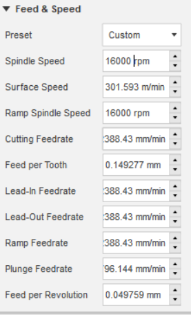
RPM/Speed=how fast the spindle is spinning. I started out cutting AL at around 16k rpms, but now i cut at 20k+. I’ve seen plenty of folks cutting at 25-30k, no problems. No need to slow that down.

Air blast= either rig up a nozzle to blow air on your endmill or be prepared to stand there with an air hose. Biggest problem for me is when the chips don’t exit immediately (especially on deeper cuts) and they get picked back up by the endmill and cut again. And again. And again. The heat they should carry away gets reintroduced, and the stock starts to get gummy when it warms up. Also artificially increases the chip load, creates even MORE heat, and borks up the surface finish.

Feed rate/chip per tooth. How fast the steppers are driving the spindle. First figure out the spindle speed (rpm). Multiply that by flute count(1) and desired chip load (chip per tooth, 0.001-0.002 in = how much material is cut by each flute on every rotation). Say you’re at 25k rpms. 25000rpm*0.001in/rev 25in/min. Similarly, 0.002–> 50in/min. I like 0.001 on the low end to reduce tool rubbing, which is when the endmill doesn’t get a big enough bite to shear off a chip and instead the uncut edge of the stock just sort of smashes instead. Makes a lot of extra heat and will wreck your endmill, maybe your day. 0.002 is about as high as I’ve gotten on my mpcnc and with your long gantry may be your limit as well. Of course, if things are going well maybe you can beat that. You can increase the cpt on the fly by increasing the feed override.

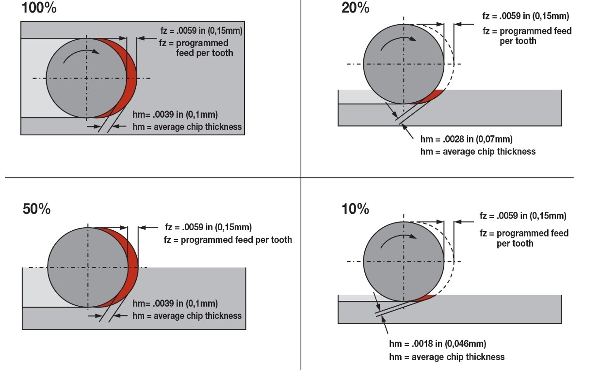
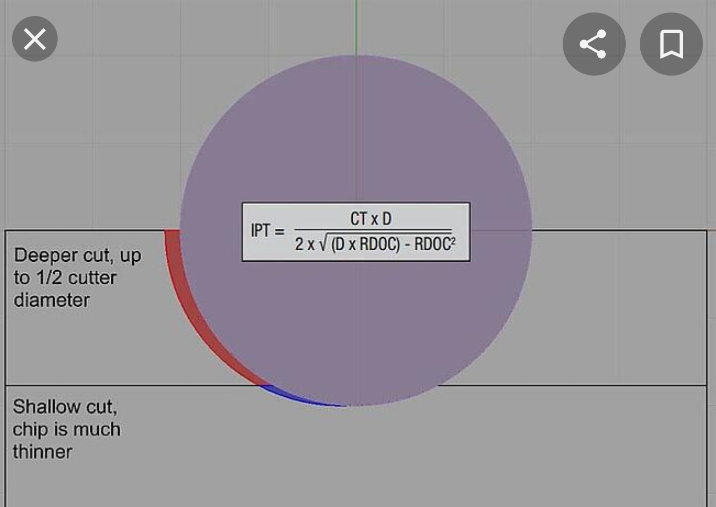
Chip thinning is when you have less than a 50% stepover. I’ll find a picture to post in the next comment, because it’s much more efficient than trying to exclaim with words. Basically, the father away the center of the endmill is from the stock, the thinner the chips are. That’s another way of saying less chip/tooth, which can result in (again) rubbing. Solve this by investing the feed. There are formulas to calculate the exact chip/tooth, or if you’re good with trig you can derive it.

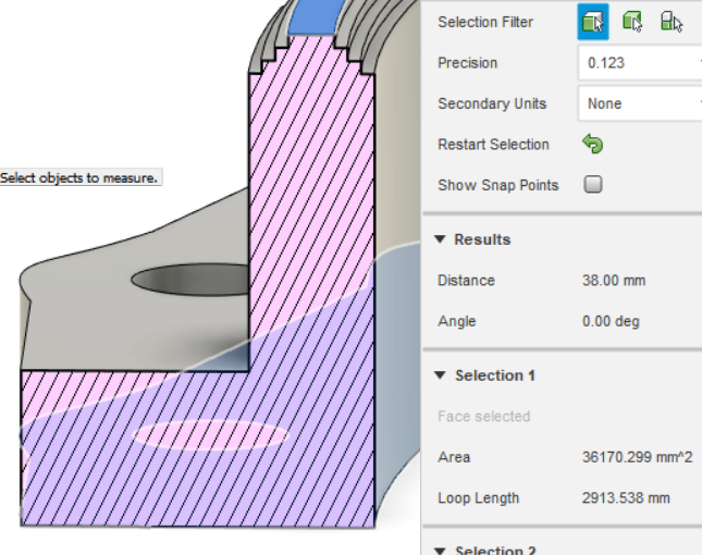
DOC = depth of cut. How far down do you want the endmill to go on each path? Rigidity will always be our first problem, and you need more rigidity to go more deep. I had am 8x10 mpcnc for a while, and I’d cut 0.04 to 0.07 with 1/8 endmills. You can get the same (or better) MRR (material removal rate=DOC x stepover x feed = cubic in/min or cubic mm/min or whatever) at shallower cuts and faster feeds…and you’ll probably get better reliability.

HEM = high efficiency milling. Definitions vary, but the strategy relies on going deep to utilize more of the flute, lighter passes to keep horsepower requirements reasonable, more flutes to keep the MRR up, faster feeds to combat chip thinning, and higher rpms to speed everything else up even more. It tends to not work well for us because of rigidity (rather, lack of) and speed/feed (again, lack of). We can learn a little from it and really spend a lot of time optimizing the adaptive/trochoidal strategy to not fail, but at the end of the day we just can’t get a high enough MRR to justify the attempt, in my opinion. The strategy is still useful in terms of making extra space for chips to leave (vs slotting) and reducing tool loads (vs pocketing, especially in corners), but we seem to be better off using traditional thinking of smaller DOC and higher stepovers.

Let me know if I missed anything.

2 Likes


Also, the top pictures demonstrate climb milling, where the flute cuts into the stock such that the chip starts at the thickest point. The alternative is conventional milling. Imagine, in these pictures, the chip starting at the bottom and being sort of scooped out of the stock. It’s the same way we run routers on wood or at router tables to keep the work from flying away. Fusion 360 sometimes refers to climb milling as left and conventional as right, depending on the strategy.

I’ve never seen anyone recommend conventional milling alunimum on desktop machines, or even in modern larger cncs. It has some great uses on machines with measurable backlash (since it sorta loads up the machine) or on certain materials, but the only time I use it is when I’m finishing wood with a 1 or 2 flute. Looks and feels a little smoother to me. I tried it to finish alunimum once, and it looked like boogers. Climb wins everywhere else, since belted machines dont really have much backlash at all. Certainly none that I can measure reliably.

1 Like

Are you slot milling?

Thank you for the in-depth explanation, I was mainly concerned with chip per tooth but you can never have too much information when learning.

you are right about the gantry, the wires do run thru it, but the stepper are on the main rails. so if i move the main rails in I have to lengthen the wire or pull everything apart to accommodate. the additional cross beams wont help with gantry flexing but it would stiffen the frame which wont hurt. again everything is 1’ chromoly steel so I can literally stand on my frame without damaging it. But as constructive interference builds, the vibrations along the frame tubes may become an issue at the 17x17 point. which is why i’m looking at the braces. I do align parts at 0,0 of the 4th quadrant… so my x always runs negative and my y runs positive. There is a column in my garage that blocks me from using x positive. See pic

You make a good point about stiffness in the corner… i may adjust the orientation so that the critical alignment holes are along the frame, I hadnt thought of that. the circled bolt holes are for the alignment dowels on the engine and the left one is pretty frame out in no mans land.

just so everyone has a better understanding, that mounting flange is 12mm thick. that ring section is 10mm and the full height is 38.5 or whatever 1.5’’ is in normal units. That gap in the upper portion is the starter which is engine mounted. The entire design is actually 2 pieces, I have another plate of 12mm that will be cut and welded to the ring and the transmission itself, but after this that should be an easy task. The chamfered edge on the ring is to help with penetration on the future welds.

1 Like

I do a 3d adaptive for the main flange area, 2d wont cut around the opening for whatever reason, but 3d doesnt care.
I bore the bolt holes
the chamfers are contour passes as well as the inner ring and outer flange cuts to free the part.

ETA: all the tool paths are straight, no cute little circles like I would expect to see from videos and what not.

Cool. I want sure which part of the quote was jibberish, so I went all in. Maybe somebody else will read it, too.

So then this piece is 10mm+12mm= almost an inch? If that’s right, the 1/8 i mentioned earlier will reach everywhere, although I’d still prefer a 1/4 for this much cutting.

On the contour cuts to free the part, if you can adaptive all the way down to 1/16 or so above the bottom and then contour from there you’ll spend a bit more time cutting, but save a lot of headaches.

If that isn’t appealing to you, check the roughing passes (4th tab in fusion) and make sure to check that box. It will start the contour too far away and run a second lap after that. That will make the slot wider, which helps chip evacuation. Two ways to do this
1+ rough, 1 finish on each depth
2+rough (on each depth) and finish only at final depth (there is a check box for that one).

Also, if you have time, consider making a post about your car in the “off-topic” sub forum. Quite a few motor heads in here, and I started a post for my kit car there.

Kinda funny that i ALSO started my mpcnc because i want to make some foam bucks for body mods. Obviously much smaller scale than what you seem to have planned, but…same idea.

I don’t see anything there that jumps out as being concerning to me. What are the feeds and speeds you’re using, and what cutters are you using?

My fault, the ring is 10mm thick… not tall… the ring is like 28mm tall


my paths on adaptive and contour, visually, appear identical. the outside of the flange is all junk, if i widen the cut to allow for an adaptive path thats not an issue. I only contour to save machine time. The inner cut on the ring is another story, that material is reserved for another project. so I cant widen it much. but i’m willing to give it a go.

Surface finish is not a concern, so I dont know if the finish pass is needed if i drop stock to leave to 0, no? I just have to make sure those alignment pin holes are really close to dimensionally accurate and the inside ring is pretty close, I think there is 5mm gap on the radius between the ring gear and part. i’m more concerned about deflection at depth.

Maybe this spring, I am not far into the project and the first big hurdle was getting the engine to run on the standalone. its the S85B50 V10 and its notoriously problematic, BMW what can you do. Now that I have that worked out I want to make sure the trans can mate properly before really diving into the body. I have a lot of the suspension parts modeled and jigged but everything is in small pieces at the moment. This is my 3rd race car but 1st ground up build. I kicked around the idea of an SLC or K1 instead of one off, but then I saw the s85 SLC and the renevatio and didn’t want to copy someone else’s build. The irony in that is the motor and trans combo were chosen because of the s85 exige.

The finish pass is great for dimension. Definitely include it on the pin bores. When contouring, the only real differences between rough and finish are stepover and feed rate. You can absolutely skip thug finish if dimension and surface aren’t important, but it’s the same as just having a fast finish with a biggee stepover. 6 of one, half dozen of the other.

As for reserving the interior of the stock, only you can answer the following question:

How likely is a contour path to jam up and scrap the whole job?

If you have to start over anyway, may as well use a reliable strategy and just buy the second stock for the other part.

I think slotting is fine, but i haven’t had much success going deeper than the mill diameter on a single width. If you can test it and feel good about it, do it and take video. Then good or bad, you’ll get views.

Right now I have speed tiger 1 and 2 flute 1/4 end mills in various flavors. I just found an speTool that is 1/4 but 3’’ long, which I might give a go because every other tool is barely hanging on inside the collet, most of them are 2" OVL, but 1 style of the 2 flutes is 2.5. all of them are carbide upcut.
I cant find bits with any style of finish that I can get here by the end of the week. I’d rather not wait til xmas to make my next attempt.

I also have some 4 flute bits in various sizes that I use more my normal milling, but i’ll give you a guess what bits failed on the sheet metal trials.

E: wrong quote… sorry David

Good question… if it fails it fails… its only like $200 for the entire plate… that sounds pretentious as hell until you recall the 10k engine and trans combo I mentioned earlier… and if this works out well, it will save money later by allowing me to machine more of my own stuff rather than farm it out… so in the end it may pay me back.

so like I said, i’m willing to give it a go.

Well, know that we’re rooting for you! If you can set up a video to record, it might help diagnose any trouble you run into.

image

I had to modify a bunch of things to get fusion happy with the boundaries i need machined… but thats finally done, all the deep cuts are adaptive, I left the chamfer as a contour, and I left the bore.

Fusions default feeds and speeds, any good? its custom because I modified the spindle speed.