Well many know about this build already and it was suggested by a few to run a build thread for it so here it is…
Project is to take my mostly stock Creality Ender 5 Plus and put the Zero G Mercury One.1 CoreXY Conversion on it.
Printer Specs Currently:
Ender 5 Plus 350mmx350mmx400mm
Microswiss Direct Drive Conversion with All metal hotend
BTT SKR Mini E3 V3 Control Board
Klipper Firmware
Plans:
CoreXY Conversion
Orbiter v2 Extruder
Rapido HF Hotend
CPAP Part Cooling Single 5015 Part Cooling fan (for now)
SKR Pro v1.2 Controll board SKR Mini E3 V3 (Down to one SKR Pro left. If I am able to revive the Octopus or either of the burnt SKRs then this will get revisited)
Z Tilt adjust with Dual Z leadscrews (already on the printer, just going to split them apart for tramming the bed, not as good as 3 but better than just one LOL.
Staying with original heated bed for now
Not planning the Hydra mod for this build since it already has dual Z and that adds a lot of cost for a 400mm Z. I do also have an Ender 5 Pro that I plan to do the CoreXY mod to, and that printer will get the Hydra mod to get rid of the cantilevered bed.
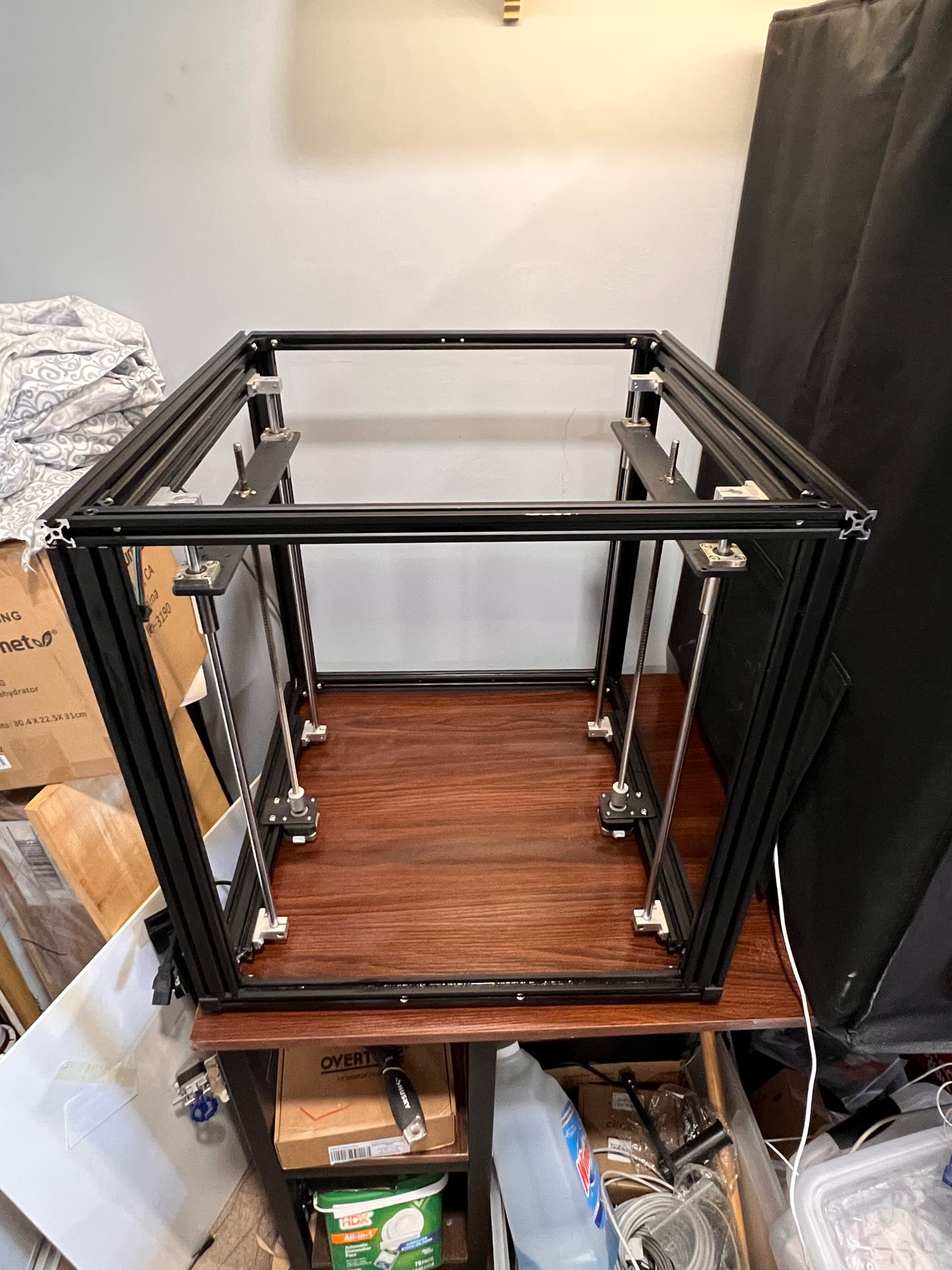
I’ve been printing the parts for a few days now in Polymaker ASA Orange/Grey. Down to the last few “I forgot” parts now. Earlier today I took the E5+ apart and down to a bare frame - Z leadscrew and bearings. I have the DXF file for the bottom plate pulled up already but have not cut it yet. Will be installing Din rail in the bottom for all of the electronics and want to get that laid out some before I cut the panel. That way I can put the screw holes where I need them for the Din rail and everything will be lined up nice and straight. I also found a DXF for a top panel for the electronics bay at the bottom that I will probably cut out of a piece of 1/4" polycarbonate I have laying around. Was planning to do the bottom plate from 1/4" plywood but I’m actually thinking about doing it out of 1/2" that way I can easily screw down wire hold downs and it will add a bit (not a ton) of weight to the base, Probably not enough to matter but cant hurt either LOL.
Well here is the only pic I have so far. I will do my best to take pics along the way and post them as I get parts done. Already started on the worst part of the whole deal. Sanding the dowel pins to fit the bearings. Got 3 done, 7 to go LOL
That bed lift looks a little like my gridbot v2. Except mine has a belt driving both leadscrews from one motor. I was a little skeptical, but it has been rock solid. I bet this is going to be a slick printer.
Thanks Jeff! I sure hope it is lol. With the only in depth build under my belt being the V4 this is a very different process. And their documents are very lacking. Instructions start off okish then just stop and that’s it. Everything else is just look at the cad and figure it out or ask on discord lol.
Yeah. The gridbot was a CAD file and some photos. The creator (stewart) was holding my hand and my forum post about helped a few people after me. That’s all part of what makes it special sometimes.
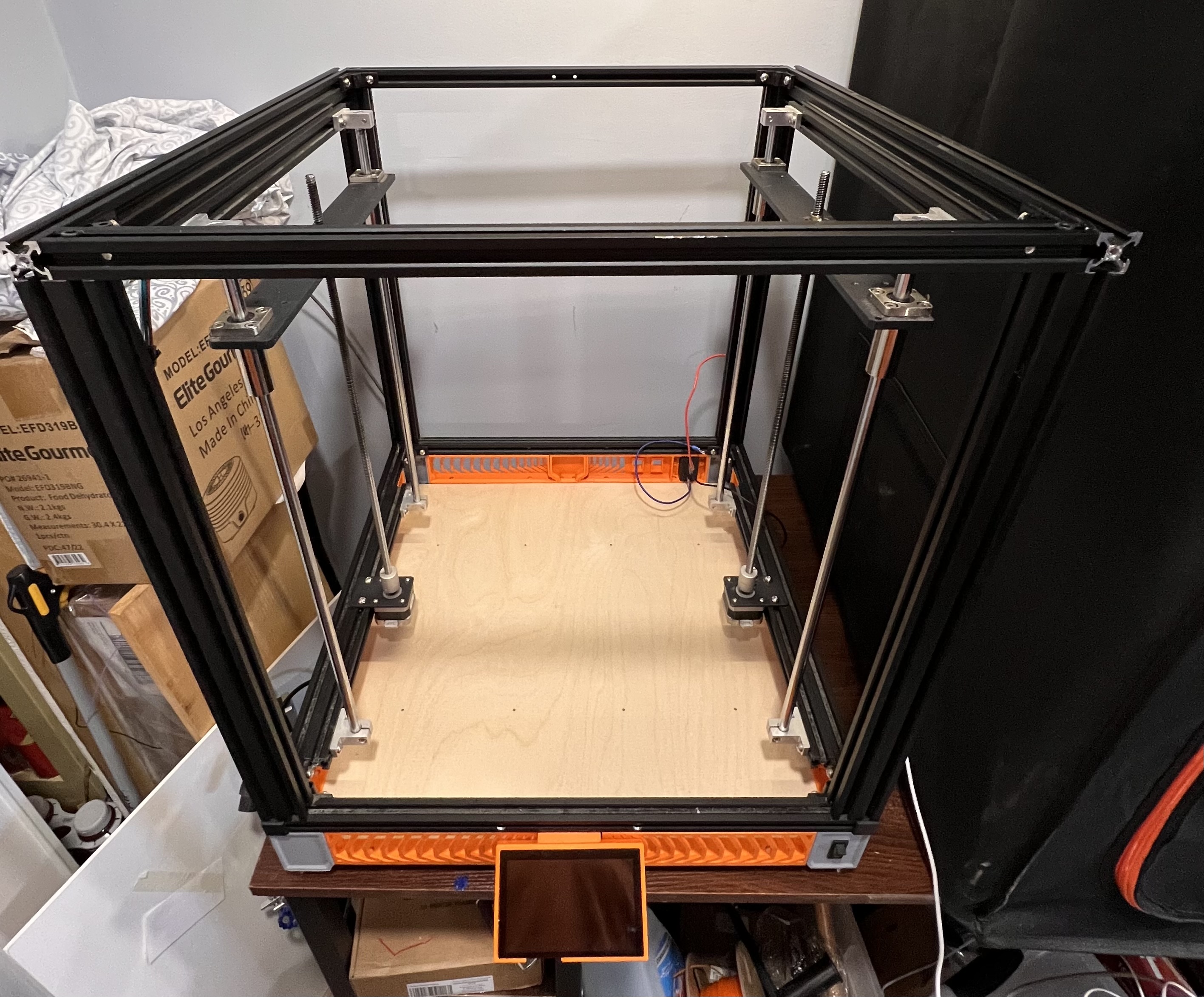
I’ve been slacking on the build thread here. Been working on it as much as I can between everything else. I got the skirt all installed, cut the bottom panel on the LR3 and installed that as well. Little surprised for as nice as the cad for this thing looks the DXF for the bottom panel was a little off. Just some screw holes and not by much but still would have thought it would be dead on.
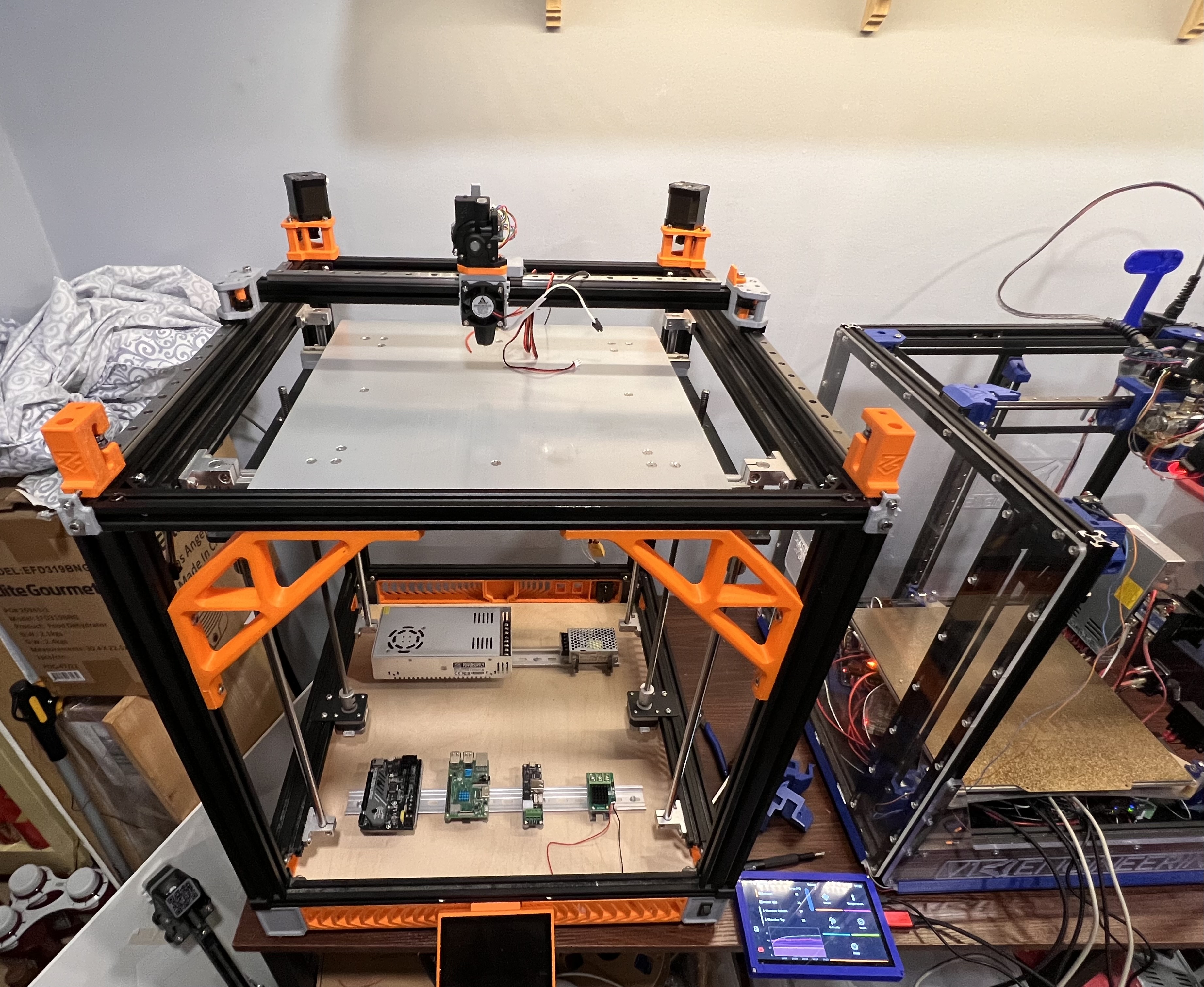
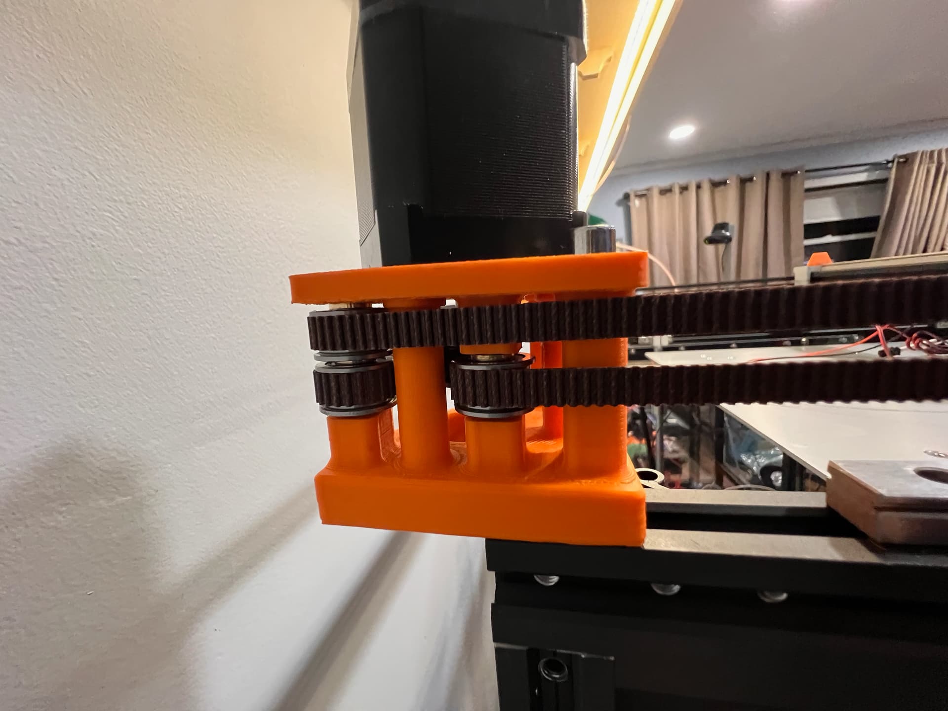
After getting all that installed I I flipped it back over and started on the top. Got the motor mounts all put together and installed. Then put the Y rails on. followed by the X beam and its mounts and linear rail. They have a neat deal to lock the X beam to the front rail before you tighten it down to hold it square. Now just have to hope that the front rail is square LOL.
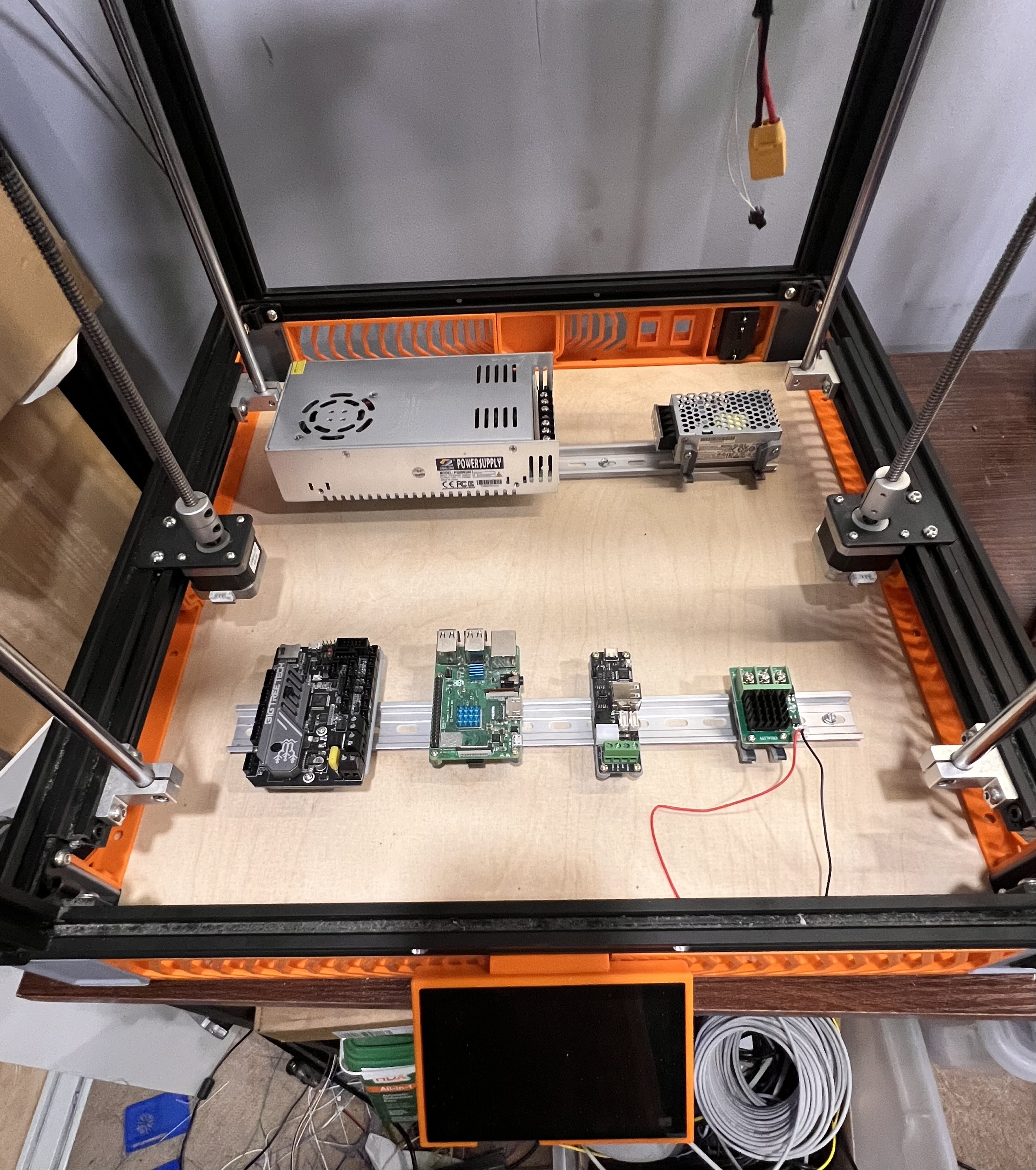
Also got some work done down in the electronics bay. Got the din rail mounted and all of the different mounts to attach everything. My first time ever messing with din rail before. Its a pretty nice setup once you get the right mount for everything lol. Still have to get it all wired.
Also got as much of the tool head put together as I could. I’m short 4 screws. M3x45mm. Amazon is supposed to be bringing those tomorrow so hopefully that will be finished and then I can wire everything up, put the belts on and then start to test motion and all.
Still a LONG way to go but seem to be making decent progress. the last 10% will take 90% of the time though lol
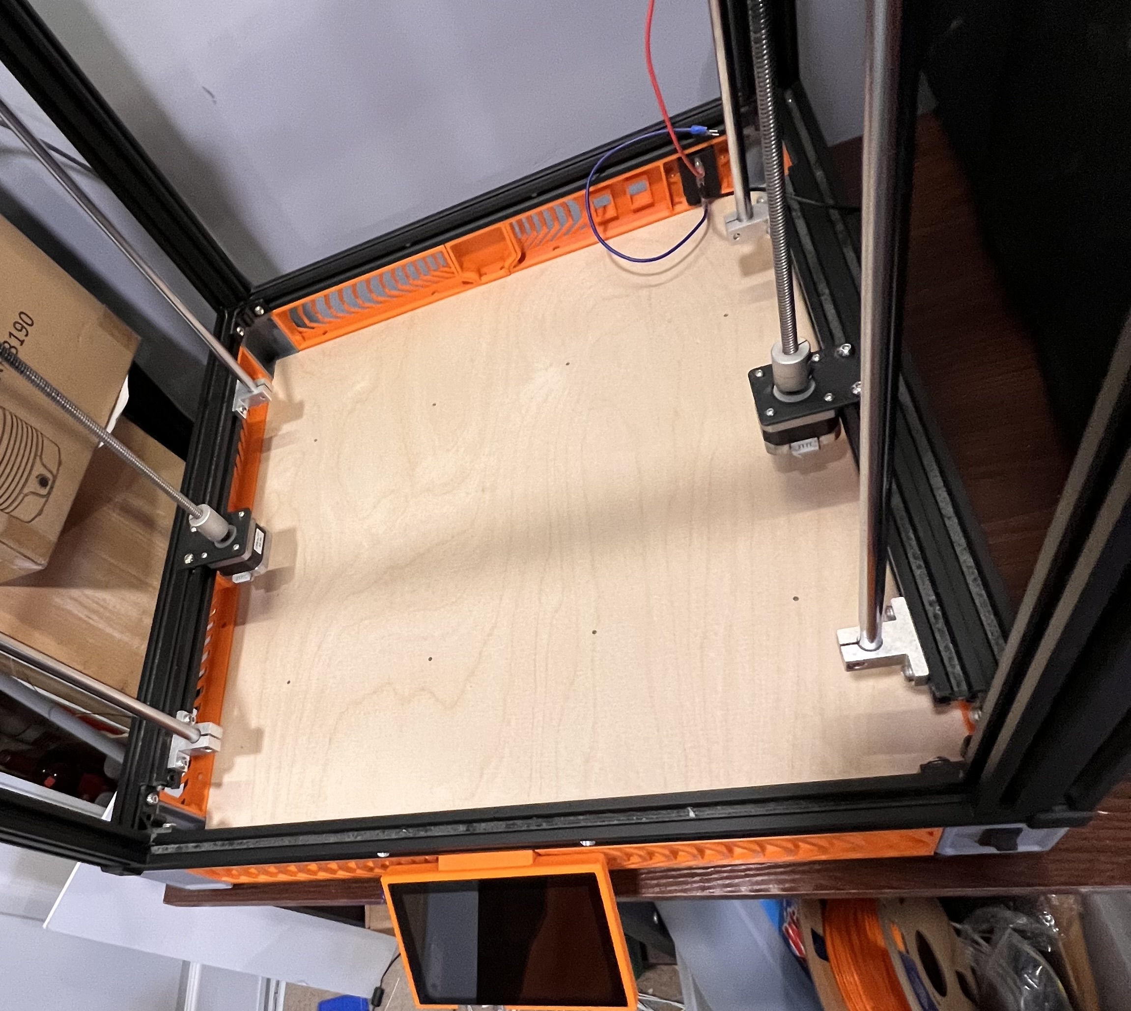
Is there sufficient clearance between the heated bed assembly and the electronics that you can’t drive it all the way down and either bump into the electronics or tangle up the wiring when down there?
How is bottom of travel in Z controlled? Endstop, mechanical hardstop, other?
Looks like maybe the LM12LUUs would hit the SHF12s before you could drive all the way down.
Yes the bearings for the smooth rods will hit well before the bed can get to anything. And everything in that area is below the lowest point even the bearings can get. With the added skirt there is now an extra 60mm of space that wasn’t there before
figuring out what bracket for what on the din rail. I bet I printed 2.5 times the amount I actually used figuring that mess out lol. All the videos say sanding the pins is the worst part but that wasn’t too awful bad. Use your own sandpaper. That paper they send in the kit is garbage
be aware if you order a kit it does not come with the hardware for the skirt. But there is a PDF that shows you what’s needed. Also the DXF for the bottom panel is in there as well. And they have the hydra top panel. On the discord there is a panel for non hydra on the plus
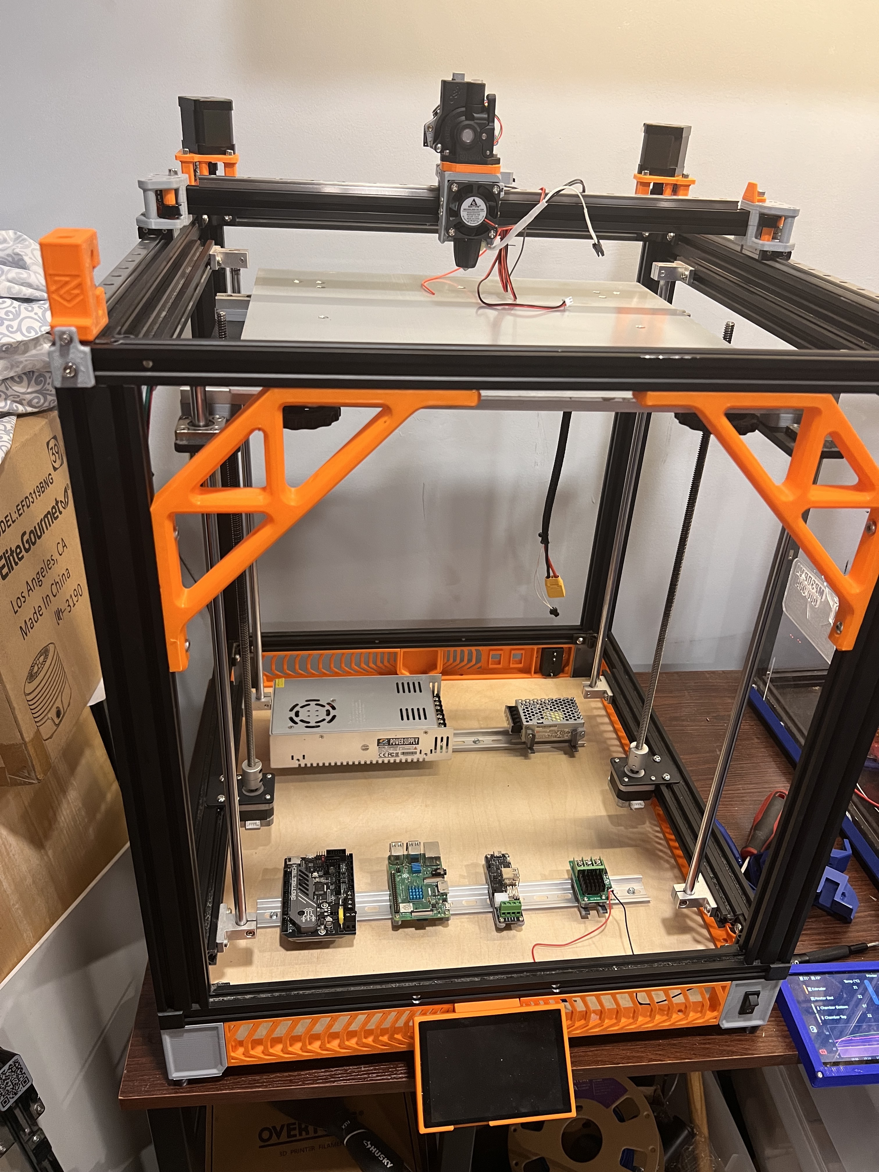
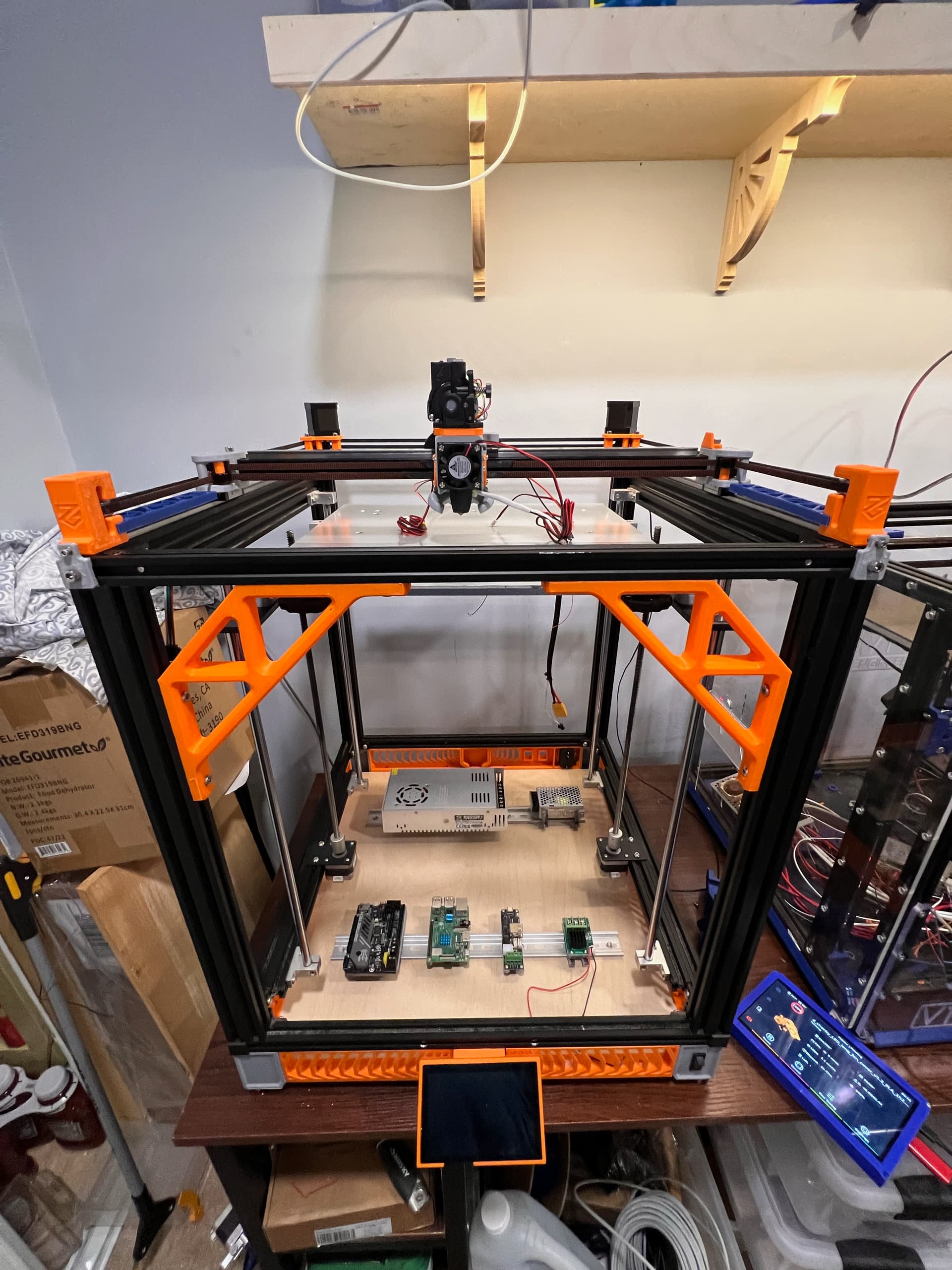
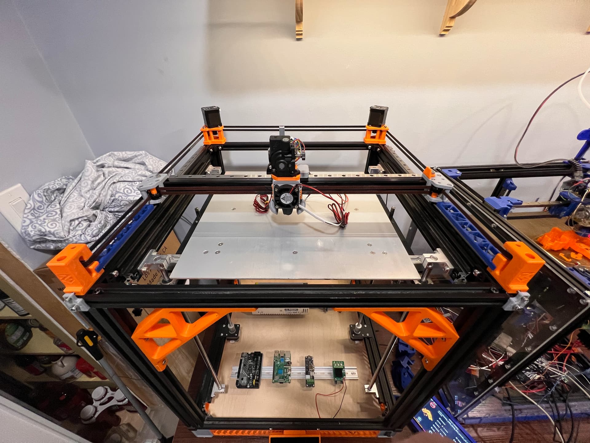
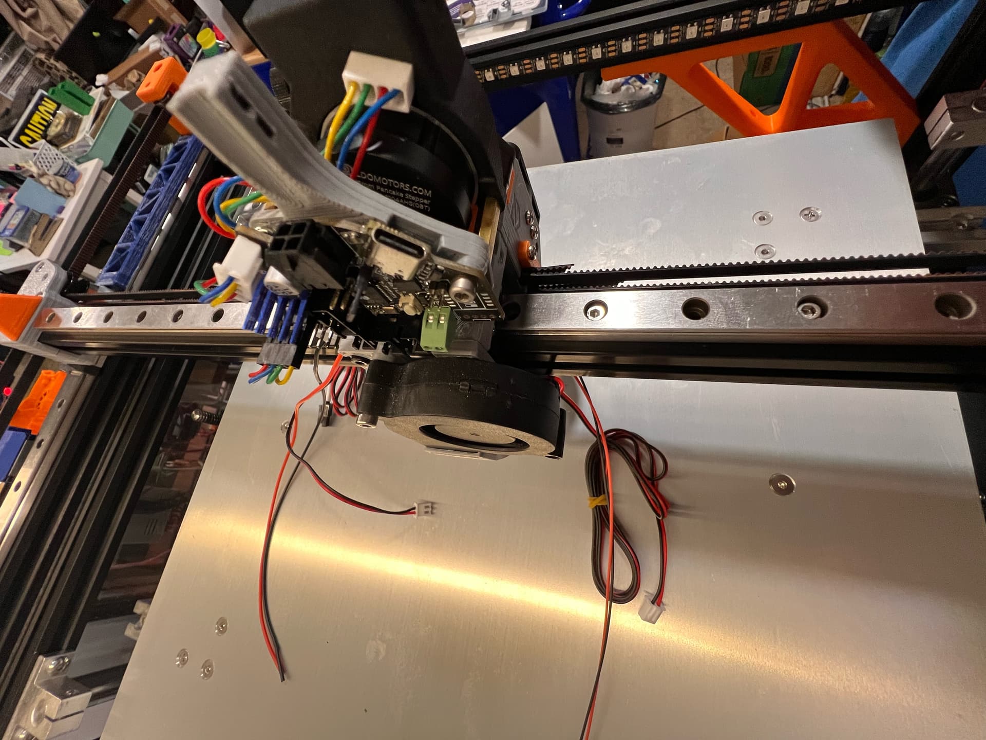
So far today I got the screws in and got the rest of the tool head mounted and the belts on it. The shroud for the front is printing now and also a turbiter to add a 3030 fan to the orbiter stepper motor. Now I need to wire all of the tool head up and also wire up all of the electronics bay. Hoping to do that a little slower and much neater than my V4 ever has been LOL.
I do need some opinions on something. As you see in the pics I have 2 90° corner braces installed on the front. This thing is not square at all and I really would like to try and help it out. So I plan to print some more of those. One in each corner on the front and both sides. Now where I need opinions. Should I just put those on the back as well? or should I cut out a panel from 1/4" birch I have and use that to square it up? The panels helped my V4 out SO MUCH. But I do not want to do them all the way around on this printer. But I’m thinking about doing it on the back just to have even more stiffness than the 3d printed brackets. Actually I also have a 3/8" piece of PVC board I could use for this as well. Its been here so long I have no idea why I ever ordered it LOL
So lets hear it. What would you pick? Brackets, Birch or PVC for the back?
I haven’t had great success with printed braces. They’re used on my TAZ, and every time I take it apart what I do when it is not tightened is I get a bunch of smaller metal framing squares and clamp those in place, then add the braces and tighten them. I end up walking all around the machine to get it right.
That style you show in particular is problematic as you can slide it around surprisingly out of square.
I’ve had better luck with printing parts that have hole patterns that are triangle shaped and install not inside the frame but on the outside. Those have much less slop especially if you keep the screw holes as tight clearance holes instead of loose.
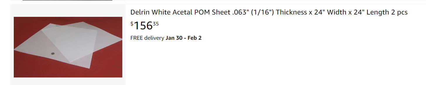
Better still is to put full CNC cut panels on there, which force it to be square. Delrin is a good choice for those over wood, as the CTEs are more similar than wood / aluminum.
Yeah I had to be very careful when tightening them to hold it all square and correct. And it did well for that one spot but cant say how they will be longevity wise.
I don’t disagree here one bit. But I really don’t want to have hard sides all the way around this printer and I don’t want to spend the money for acrylic like I have on the V4. Ill have to look around I may have one sheet of it out in the garage but definitely not 2. I have no problem with the back panel being solid. Really don’t want to spend any more money on this project as I’m already in it almost the cost of the printer new. Really would rather save my pennies for the upcoming V5 LOL
This is the PVC board I have. Its extremely stiff but I have no idea how it would do under compression from a screw head. I cant squeeze it by hand or with a pair of calipers but thats not saying a whole lot LOL
If you have machine shops or plastic supply houses near you that use/carry Delrin (Acetal polymer), make friends and offer to take cut-off scraps. It’s as close as I know of to plastic that machines like aluminum and is happy with aluminum. We use tons (Literally, tons) of this in areospace fixturing.
It’s amazing how much more rigid that frame would be even with thin material. And you can get away with 3 sides, leaving the front open, and get most of the benefits of panels to square it up.
There’s a plastic supply house not far from me that has cut-off pieces from larger sheets, I’ve snagged 1/4" thick 18"x18" pieces at times for in the ballpark $30. I haven’t gone looking for any in a while, but it’s on my to-do list for someday finishing my repeat build (which is liable to be a V6 version by the time I get off my butt and finish it)
And I know of folks that have dumpster dived pickup truckloads of acetal cut-offs from local shops.
I’ll have to make some calls and see what I can find. Problem is I need almost 24 x 24. 538mm x 550mm to be exact for the rear piece. 555mm x 530mm for each side. This is a good sized printer lol.
My local plastic shop (colorado plastics) has a remnant sale every third friday. Someone ordered a ton of delrin blocks that were 8"x6"x4" or so. They had a crate of them they were selling for $5 each. I bought on and I’ve used about 2 sq cm.
I have braces on all places possible, my frame is really square as a result of this. I used smaller braces though. I think the smaller braces look better?