ZenXY Espresso Bar

Hi y’all in the forums,

I have been fascinated by the ZenXY table for a very long time now and have actually printed but never built version 1 of it. Problem is, we do not really need a table anywhere we would not already have one. Modification of existing tables was also a nay-nay.

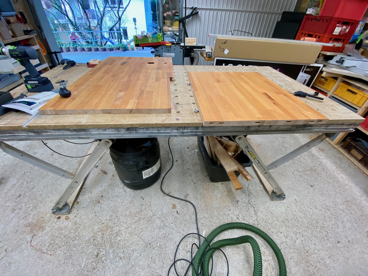
And while we sat and debated about where to put a ZenXY v2, our eyes fell upon our home barista bar, that usually looks like this:

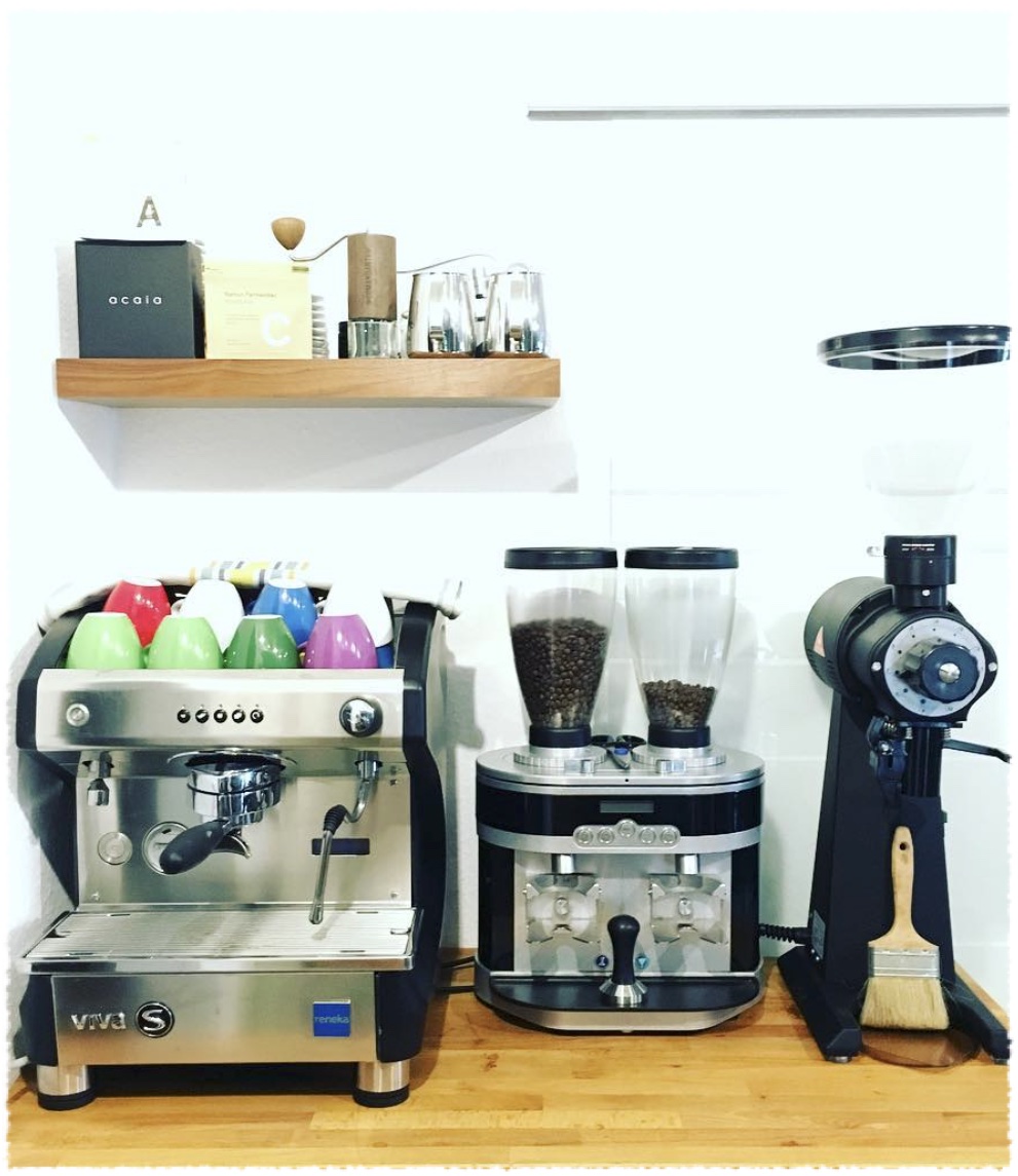
In the back of it there is a recess for a sliding door to our kitchen. I have recently swapped for a smaller coffee machine that has nothing on the right of it (no grinder etc.) and a smaller footprint. Right of the machine I want to add 100cm of ZenXY v2 footprint, which equals an X image dimension of ~816mm.

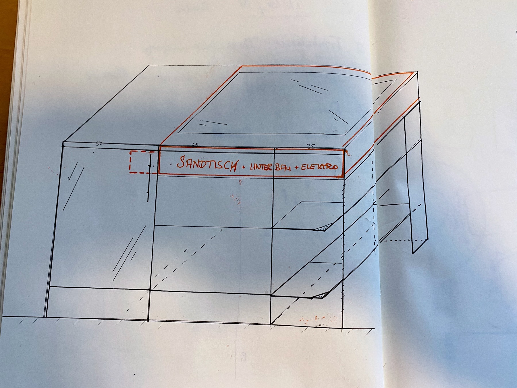
The depth of the cabinets below the counter is 60cm, so the machine footprint allows for an Y image dimension of 416. So basically a nice 2:1 ratio :slight_smile:

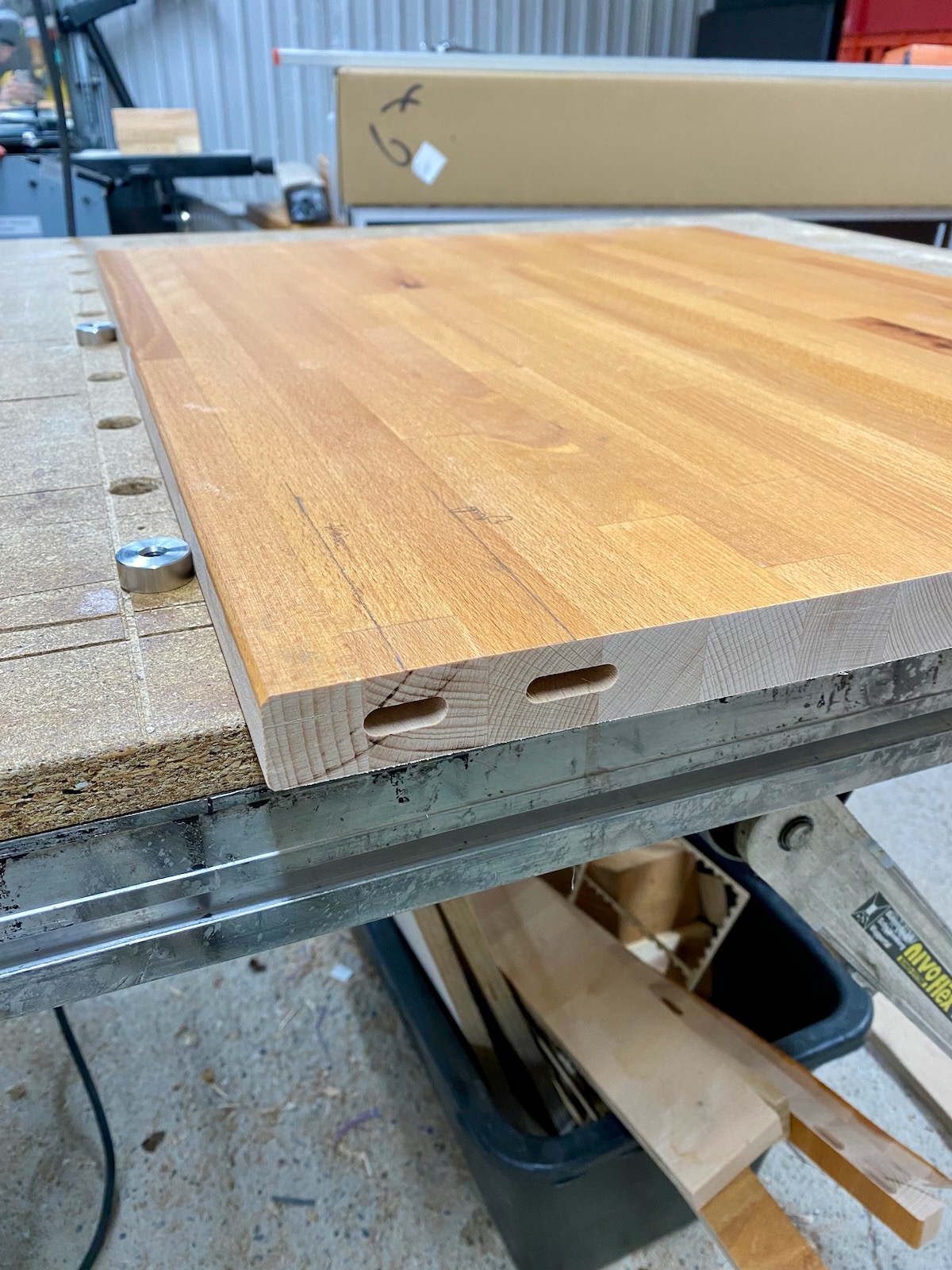
The count has a thickness of 26mm and from the top I want to cover it with 4mm security glass so nothing goes wrong when I drop the tamper some day in the future. I will NOT waterproof it, since I have never spilled something within the last 8 years and I’m OK with the trade-off of cleaning up should I ever slip up vs. figuring out how to prevent spillage going into the enclosure.

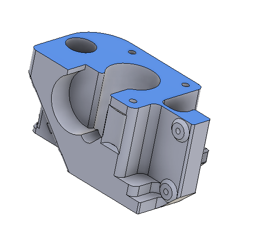
I did not stop to design anything in CAD at this moment though we might return to that for the LED strip fixture around the sand basin…
So this is all I have to go for now, maybe you can figure out where this is going from there :wink:

I will post pictures quite deliberately as people can skip the thread if they aren’t interested I think.

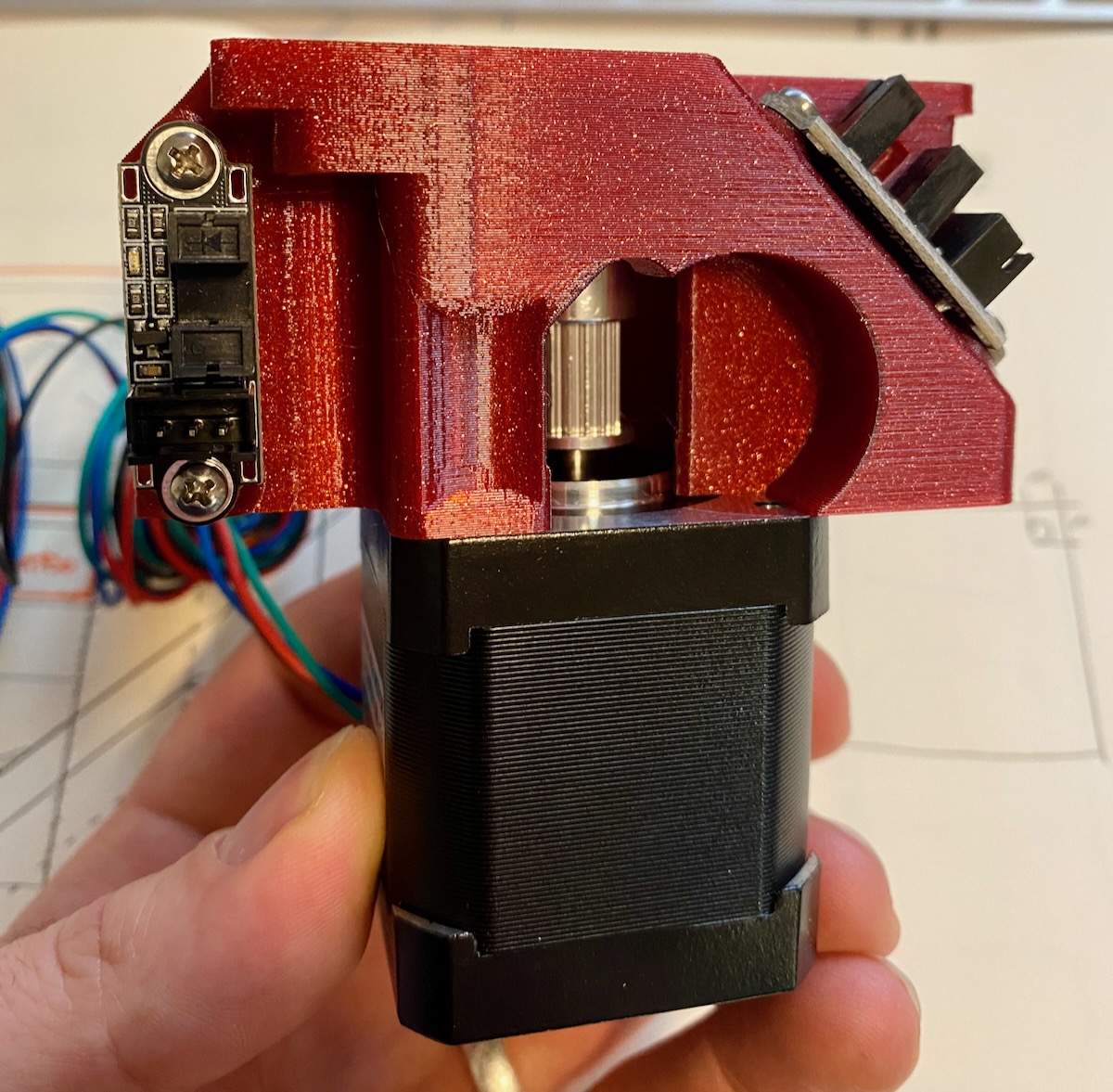
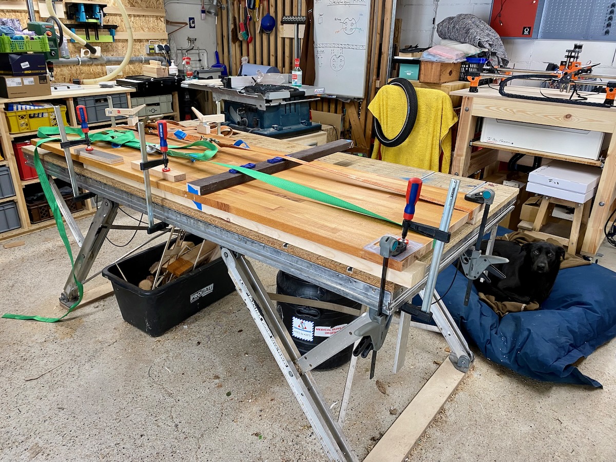
As it is currently quite pandemic around here I don’t want to go out and buy any material, so I decided to use only existing things I have in my shop (wood, etc) besides the SKR Mini Board I bought for this project.

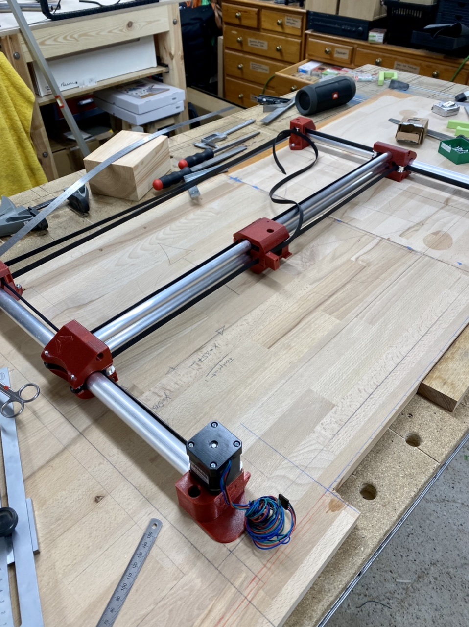
I also want to mention that this might be the first EU-version of the ZenXY v2, since @vicious1 was kind enough to provide files matching very common pipe sizes in the EU you can get for very cheap at every hardware store (aluminum or steel, 18 and 25mm required). I had asked about the rail sizes in this thread.

I want to invite you and follow along with my build. The inspiration is basically completely from @jeffeb3 ZenXY table he integrated into his work counter. We want to do the same.

Some things still bug me but I’m sure I will figure them out along the way :slight_smile:

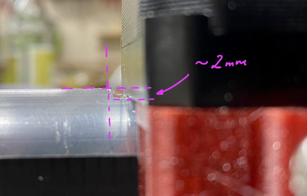
For example the distance between the sand and the top when using a 10mm steel ball. If I support it from below with a flush inlayed panel of 4mm hardboard there is only 17mm left of “air”. Is that enough? Also for the LED around it to achieve their effects? I can easily create space below since we do not plan on using the top 12cm of the cabinets for anythin besides the ZenXY hardware.

4 Likes

That is going to be awesome.

I think 17mm is plenty for the height. The ball doesn’t leave much baking soda or sand underneath a mm or two. The LEDs look best coming at a pretty sharp angle. The key with them is to have them far enough back so you don’t have to see them directly. It is ok if you still can, but it looks better if they are deep under the edge. The baking soda should be between half and a third of the height of the ball. I like it a little lower. But it only leaves a mm under the ball.

The glass surface is a good idea. Plan to have a way to remove it, in case the sand needs to be moved around or something needs fixing. Just don’t glue it shut.

This is exciting. What a great project.

Printing is finished, the parts came out great and match all the dimensions I need, maybe a liiiiittle too loose on the smaller rails, but nothing one or two layers of adhesive might not fix within seconds.

I used Prusament PETG.

During assembly you can truly notice the amount of thinking that goes into these parts. It’s genious how some of them are cut in halve to avoid supports. You can reach EVERY screw super comfortable and it’s just a joy to put together :slight_smile:

Since I do not have a 12mm magnet in the required thickness, I stacked several 12mmx3mm magnets on top. Now that I write about it… is it the same thing now as a big ass magnet? I’m not sure actually :smiley:

Enjoy the pictures:
In this part you almost can’t tell that it’s made from 2 assembled pieces. And it has beautiful resonance artifact on the v1 Logo from fast printing. :slight_smile: (What is this thing/form by the way? Where does it originate, @vicious1?)

5 Likes

I took off and cut up the old counter and took another picture from the “Starting Situation” :slight_smile:

The fridge is going to be gone and I will add a 35cm open shelve to the right to achieve the desired length of counter.
You can see on the paint that I can not move anything or I need to repaint :smiley:

I took into consideration that I will need additional stability front and back after cutting out the mid later, that’s why there are 2 dominos left and right, the wider one allows for lateral inconsitencies when gluing together (it indexes of the first one) :slight_smile:


Hehe, maybe you can spot my other v1 product in the back :smiley: :wink:

5 Likes

There might be a way to calculate how deep I would have to recess them to be invisible. Maybe I will take up the extra effort, if not I can cover them with an angled print like you I think, it looks super cool still… :smiley: Is it best if they are horizontal or do you have good experience with angled strips (maybe 5°?)

Haha I have learnt this (expensive) lesson in the past. Thank you for mentioning it. At least it was actually watertight until I had to open it up again :smiley: I will probably just lay it into a CNC-cut 4.1mm recess and use suction cups to lift it back out for cleaning, replacing the soda.

3 Likes

What is the current go-to software for regular pattern changing, wireless control and commandeering the machine as a whole, optionally take care of the LEDs?

I would love to just leave a raspberrypi there and just select a new pattern from smartphone. Does this already exist in some form?

1 Like

I still have a V1pi on mine, which is essentially just Octoprint, since that’s what I’m using. I have about a dozen pre-set sandify patterns that I print from there via the web interface. I also have a 12864 screen, but I haven’t touched that in months.

The one I built for my friend is using one of Bart Dring’s ESP32 based controllers, and that has a wifi interface to get to the files on the SD card. No LCD on that one. The wifi interface isn’t really pretty, but it’s adequate, you can upload new gcode files to the SD card, and print the ones that are there easily.

2 Likes

so i could maybe also call the octopi api from my home automation server with a timed “request” to print a random pattern for the morning… that’s actually… cool :slight_smile: and i’m confident with octoprint, might be a good thing to go for after the wood stuff that starts to turn out complicated in some aspects (stretching the machine over 2 cabinets in the upper storage is not trivial at least :smiley: ). nothing unsolvable though – i think :wink:

thank you for the idea, dan.

i’m super curious about sandypi as well, still reading up on that in the forums.

2 Likes

I am fairly certain both grblesp32 and Marlin support playlists, if you just need something simple for people to turn on and let it run.

Being able to log in from your phone can happen as well as is from the esp32, or with marlin using the v1pi. I used wled for my lights, wifi built in, but I think you could use a spare pin and make them gcode controlled.

1 Like

Why haven’t I done this? My lights are WLED. They already have a home assistant integration.

I am not using octoprint though, I am using grbl_esp32. It works fine, but it isn’t as pretty/kid friendly as home assistant.

Sandipy is something I keep saying I will do, but haven’t yet.

I don’t think this matters much. They aren’t very directional.

Yeah, by you don’t have to overdo it. I can still see mine when I sit across the room, but they aren’t troubling. If I watch the pattern, I am usually closer.

1 Like

I just inserted the belt for the first time. The way I tension this is not really clear to me. I put 3 corners square to each other, moved the axis into the 4th (also square plusminus 1mm, which should be absolutely okay I guess). Is that a good practice? Or is there some secret how-to someone could share :slight_smile: And how tight is this supposed to be? Is any (slightly) visible slack when moving the center around ok?

Questions:

  1. In the larger tube, is it correct that the belt makes half a twist while passing? It‘s the only way I got it to look like in the pictures. And I can move everything good and freely.

  2. On the side of the center truck (with the magnet) opposite to where the two ends of the belt are situated, the belt passes the center again, teeth facing the printed part inwards. Is the belt supposed to run easily and smooth through there or is it supposed to get somewhat stuck? Am I supposed to put a screw into the hole? On the pictures there is no screw to be seen :slight_smile:

And I ran into the first problem with a printed part, @vicious1. On the corners with the stepper motors, the 25mm pipe exceeds the printed part where it faces the stepper motor shaft side. I’m happy I got aluminum pipes so I could just grind it away in a few seconds with a file. Since the pipes are indexed from the “upward” facing constraint towards the table I don’t think it matters too much and they are no longer able to twist, who knows what that‘s gonna be good for :smiley:


I will now measure and lay out the cutout with the machine mounted to the plate. I feel that‘s as precise as it‘s going to get and it is less guesswork than just offset measuring. I‘m always going slow and quadruple-check everything about cutouts, since I have too often cut away more than neccessary :smiley:

So I mount all the corners so they are square. Then tension the belt, this is different depending on size, but does not need to be very tight at all, no load, not a printer or cnc. So just get it so the pulleys do not jump teeth.

That center part you have a question mark on is how you balance the tension. So you move the gantry all the way to the stepper side. If the tension is unbalanced, one roller will be not touching the stepper block, move the belt a bit to square up your gantry. Then use a nut and screw to lock it in place.

1)yes, smooth idlers get the smooth side of the belt, idlers or pulley with teeth get the teeth side. no more than half a twist.

2)Mine kinda ratchets with each tooth, but if you try it can be more finely adjusted. Yes it needs a screw.

Crap! I did leave a small overlap to lock the rail in place but it should not have been 2.5mm. I will take a look at the CAD. Thanks and sorry.

1 Like

Same issue of about 1.8mm on the 18/25mm version. I’ve adjusted the CAD for me, thanks for sharing the STEP files.

Did you move everything down or will your machine now slope down towards the steppers? You will either need thicker back spacer or move everything down.

I’m not sure if I got you right, I just extended the motor mount plane 1.8mm
ZenXY
This should not change the geometry of the machine.

3 Likes

That is exactly how I would have done it in order to not change the machine geometry.

(I might also have moved the plane for the motor mount screws the same distance.)

1 Like

Gotcha

Hey everyone, just wanted to let y’all know we had a pandemic-related incidence and the project was paused for the christmas holidays. But I’m walking over to the workshop as I write and will continue building and keeping you up to date :wink:

Have a good year everyone who is following along :slight_smile:

7 Likes

I got some work done yesterday. Will post about progress later.

Quick question: If I move the steel ball around it works well, the board has a thickness of 10mm. I would love to hear an opinion on how „strong“ the bond between magnet and steel ball should be, feels kinda flimsy to me, but that is of course when I poke it with my finger. From what I learned from other thread is that there are just a few mm of soda (how much actually approx.?)… so it should be fine. Or should I get a thinner board maybe? :face_with_monocle: I‘m confused :sweat_smile: I could put some soda on the board and try maybe?

What are other people using or what did you test and saw fail spectacularly? Would love to learn about it :slight_smile: